
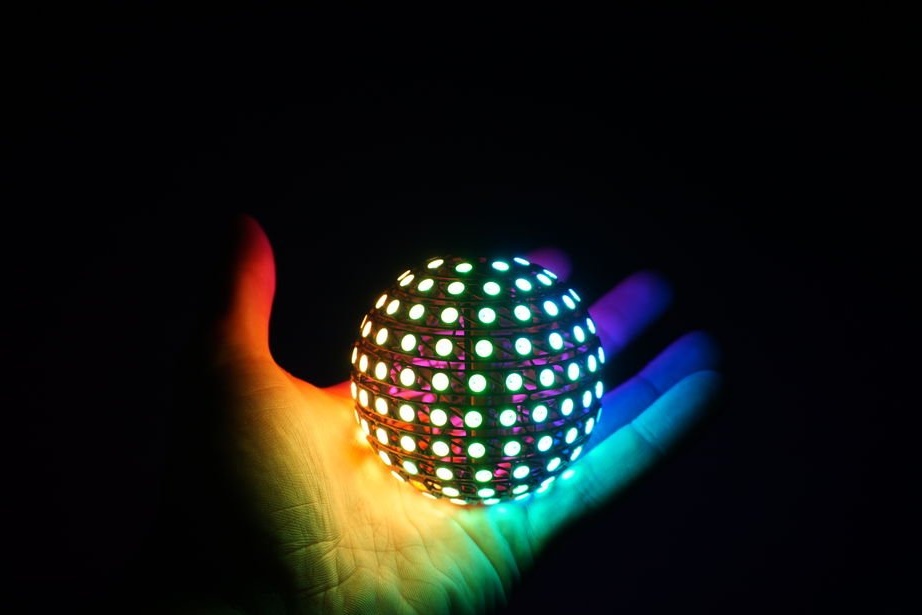
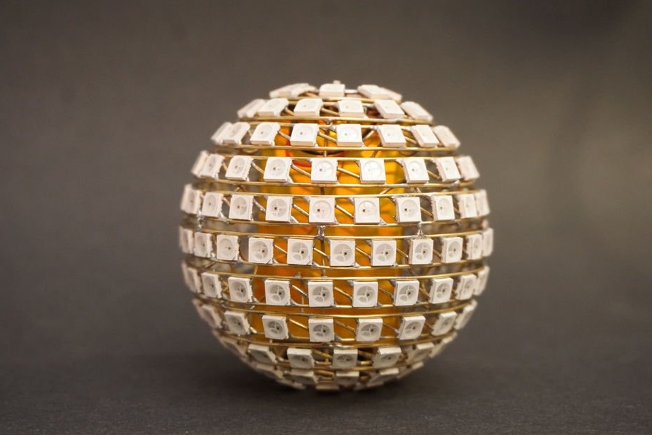
Tired of LED cubes? Let's make an LED ball. And the Master will tell us how to do it.
So, to make such a ball, we need the following
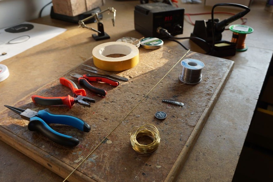
Tools and materials:
-Pliers;
-Nippers;
-Soldering stations;
-Tweezers;
-3D printer;
- Brass wire 0.8 mm;
-Soldering accessories;
- ESP32 board with battery support;
- WS2812b RGB LEDs - 200 pcs.;
-LiPo battery 1000 mAh;
Step One: Template
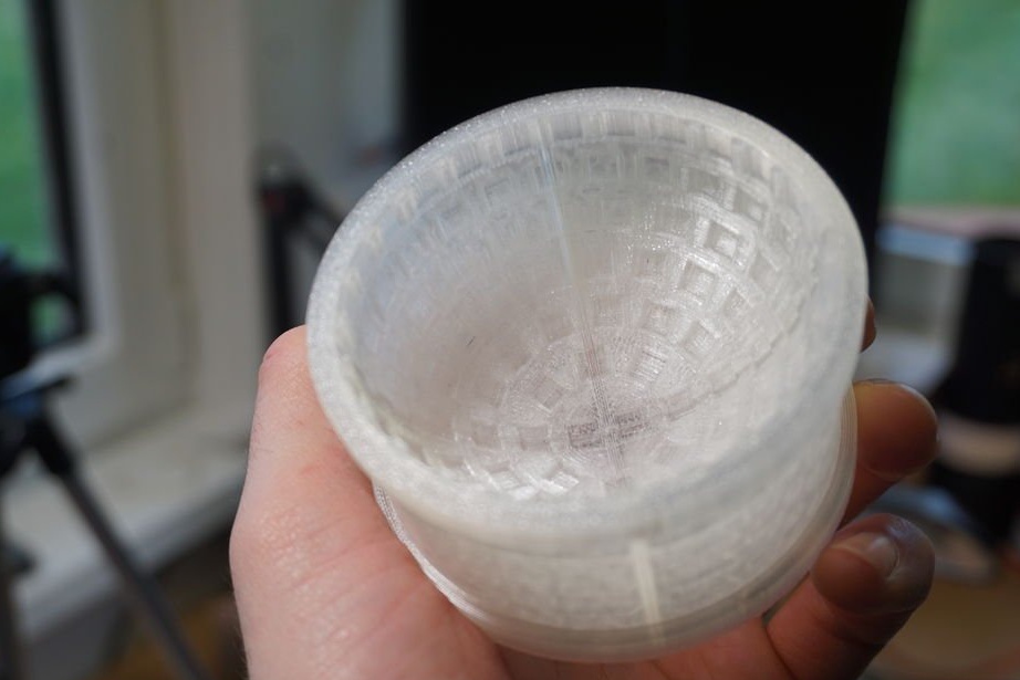
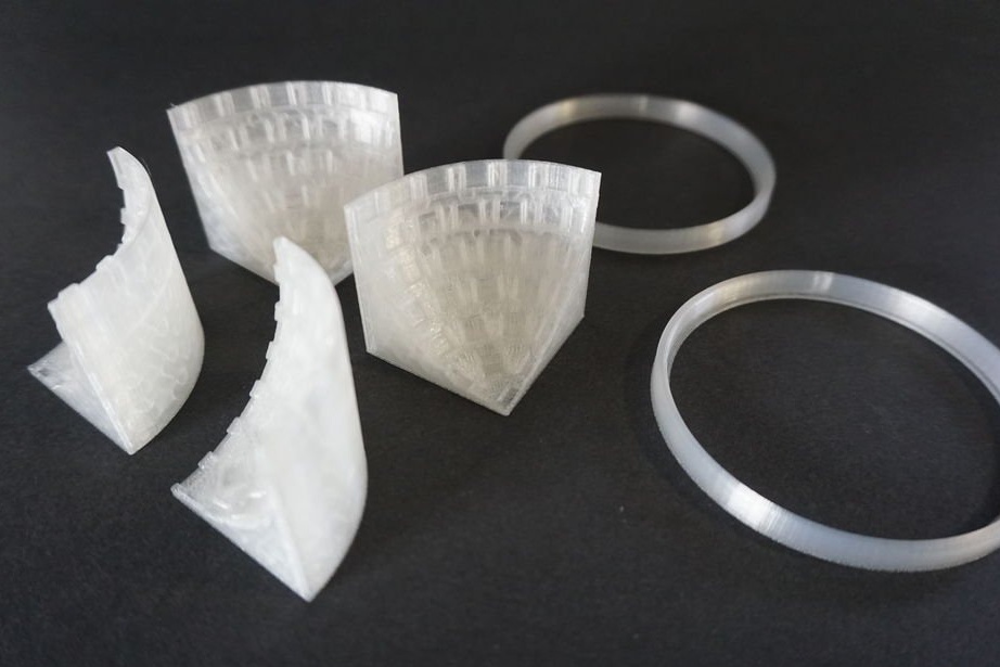
The master printed the template on a 3D printer. One hemisphere consists of six parts. Moreover, the three parts are identical to the other three parts. Below are links to files. There are only three files, you need to print two identical parts.
ring.stl
templateA.stl
templateB.stl
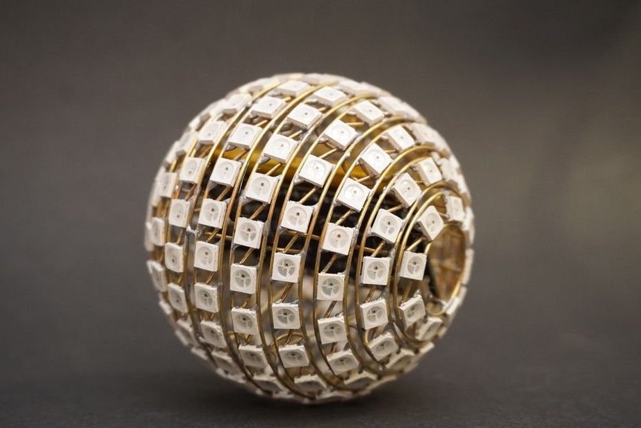
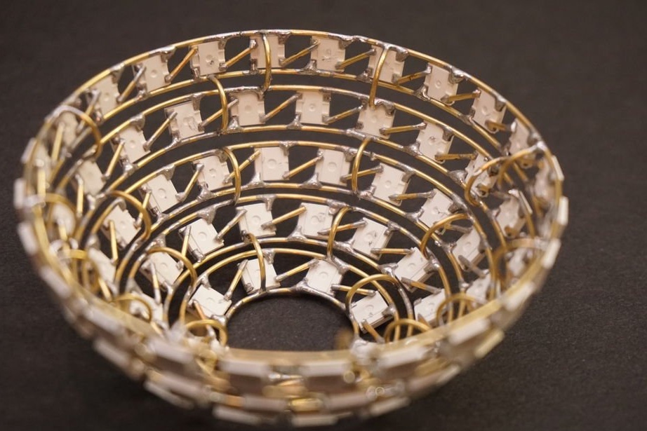
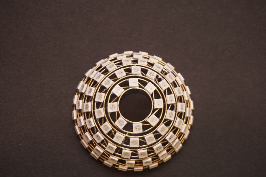
Step Two: Rings
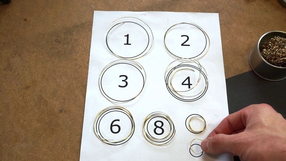
The sphere consists of 11 LED rings, each ring consists of two wire rings and a number of LEDs. For a complete sphere you need 22 wire rings. Rings have different sizes. The master made a template on a piece of paper. Dimensions are approximate and will depend on the accuracy of the bending of the rings. The master used a special bending machine for this purpose, but you can use any object that is suitable in diameter.
rings.svg
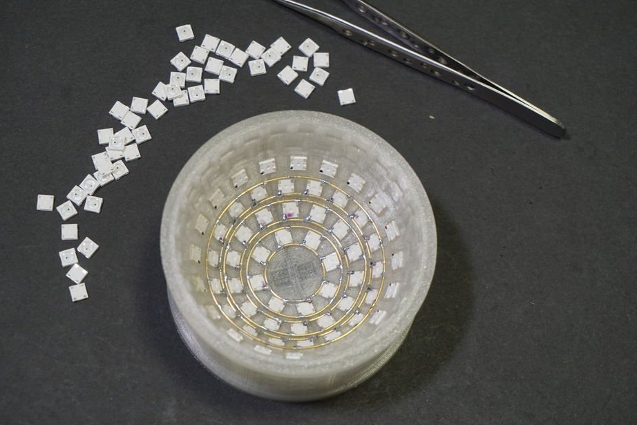
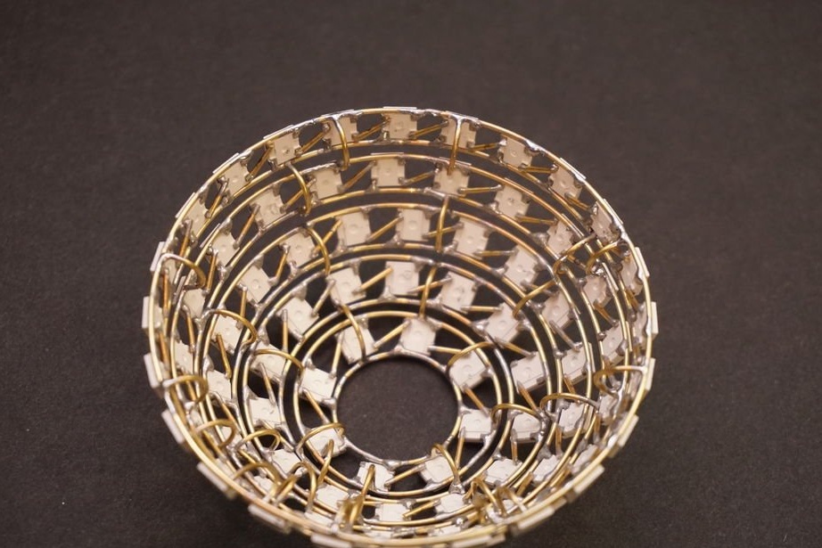
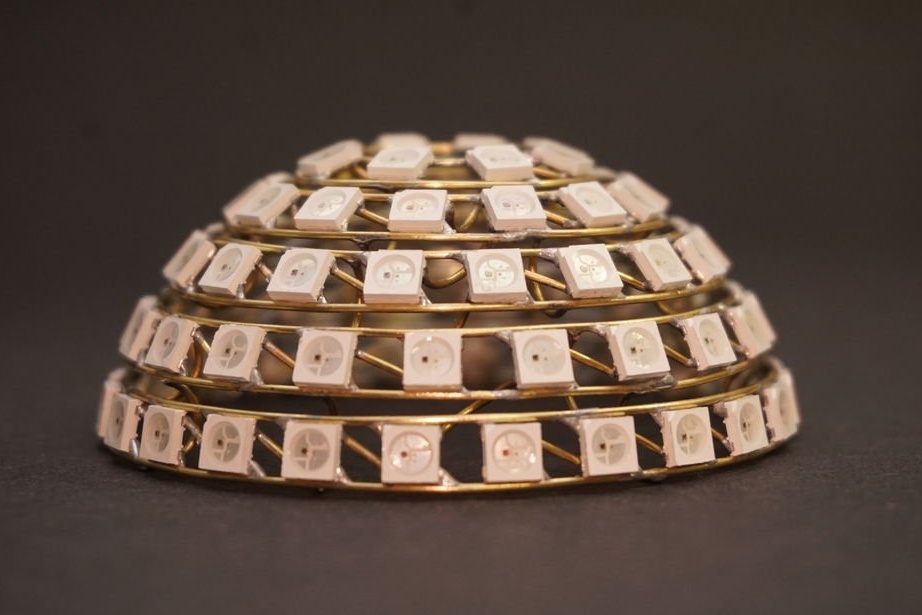
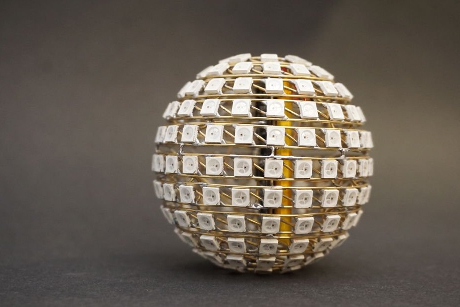
Step Three: Hemisphere Assembly
Assemble the hemisphere and place the metal ring inside. Next, you need to solder the LEDs to the ring. The bottom ring houses eight LEDs. The wizard first outlined all the GND pins with a black marker. Place all the LEDs so that the GND pin is placed on the bottom and VCC on the top.
So you need to mount six rings.
8 LEDs
14 LEDs
18 LEDs
20 LEDs
24 LEDs
26 LEDs
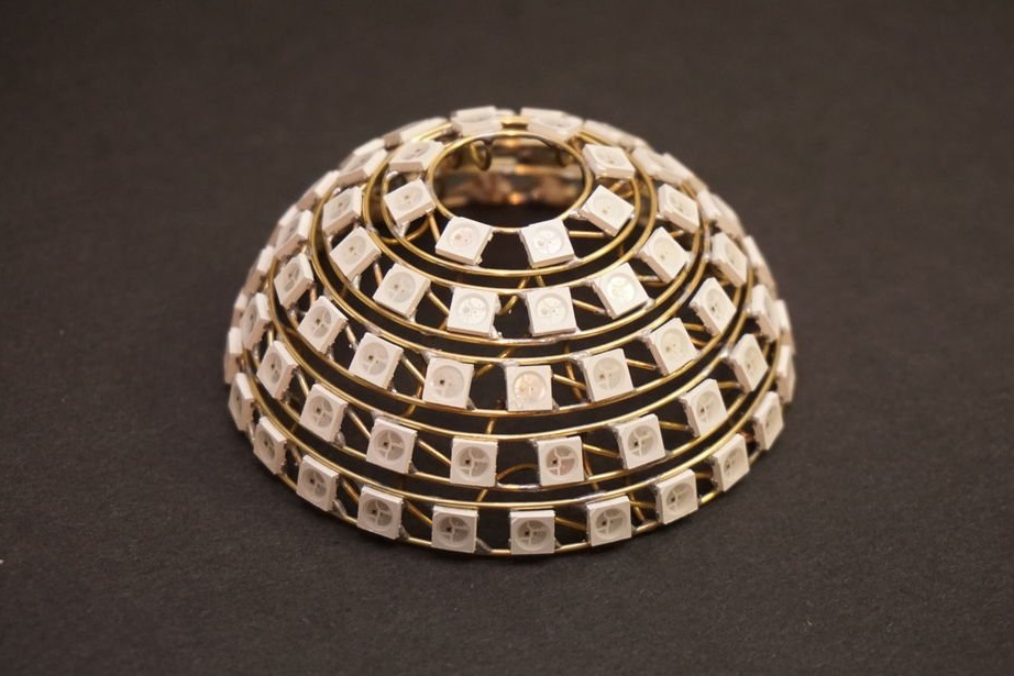
Note that you only need one sixth ring for the entire sphere - this is the middle ring. The second hemisphere will have five rings.
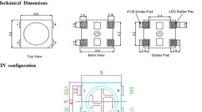
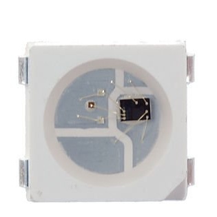
The WS2812b LED is an individually addressable RGB LED. Simply put, you only need one wire to light it with any rainbow color. Unlike classic LEDs, in which the brightness of the LEDs is regulated by the amount of flowing current, the WS2812b receives constant power, and the light is controlled by a digital signal.The LED has four outputs, two for power and two for controlling the LEDs (one DIN input of the signal wire, the second DOUT output to the next LED).

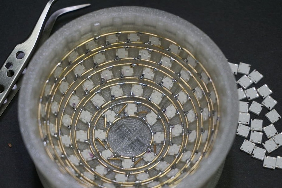
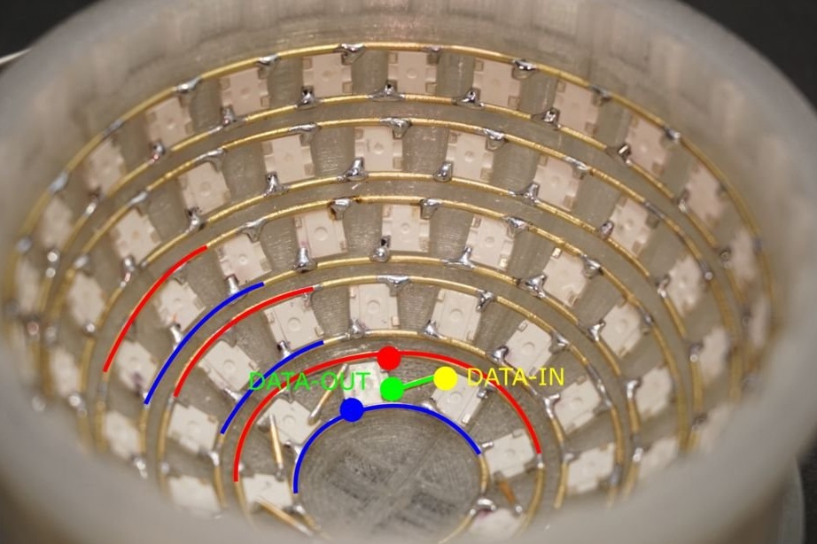
Step Four: DIN and DOUT Installation
Now you also need to connect 2 other LED wires - DIN and DOUT. DIN is located next to the GND pin, and DOUT is next to the VCC pin. The master used wires 5 mm long for connection. It is also very important to do it right. Make sure that the data wires do not touch the ground or power rings. Be careful not to solder the data pins to the power rings.
Mount one ring after another, start from the bottom. The upper and lower rings are connected using semicircular jumpers. Such jumpers will give strength to the structure.
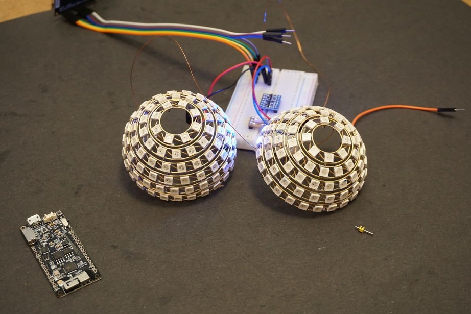
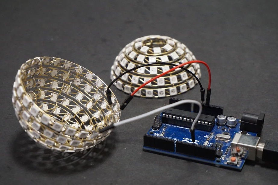
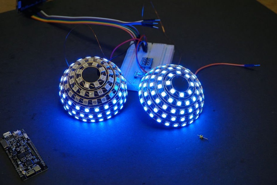
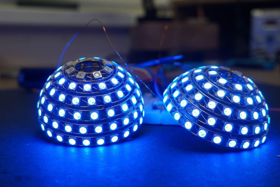
Step Five: Testing
Now you can remove the hemisphere from the mold and proceed with the installation of the second half.
After manufacturing the second hemisphere, the master performs testing.
First, it checks with a multimeter for a short circuit between the power wire and the ground wire. Then it solders two short wires to each of the grounding hemispheres and the power wire. Connect the power wires to the 3.3V pin of the ESP32 and ground.
As a result, all the LEDs are connected to one long circuit. Next, you need a smaller ring (5 pieces) and connect its DIN to the IO21 pin of the ESP32, DOUT board to the DIN of the second hemisphere. Next, turn on the ESP32 board and download the code.
If some of the LEDs do not light, then you need to fix the installation.
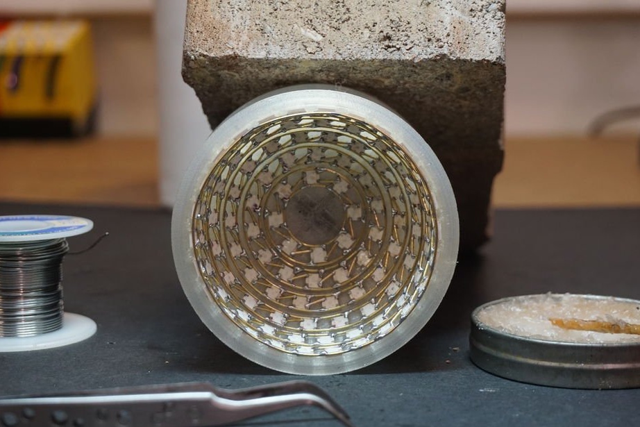
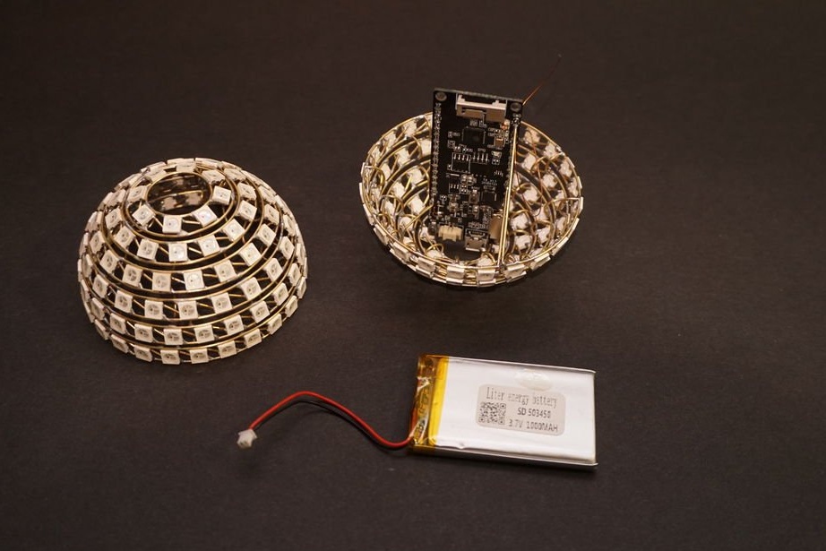
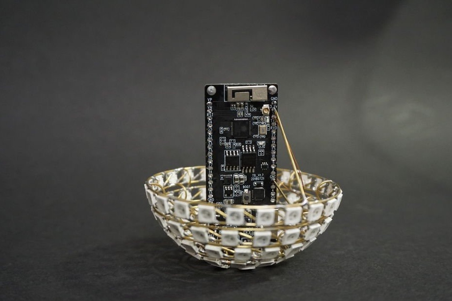
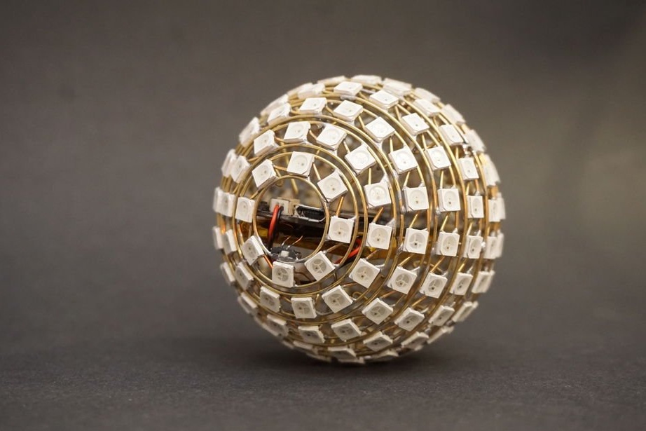
Step Five: Installing the Microcontroller and Battery
From the board you need to unsolder the switch and solder two wires to the place of contacts.
In the corners of the board there are 3 or 4 holes for screws, the master tins them with solder.
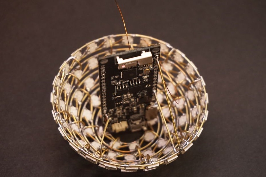
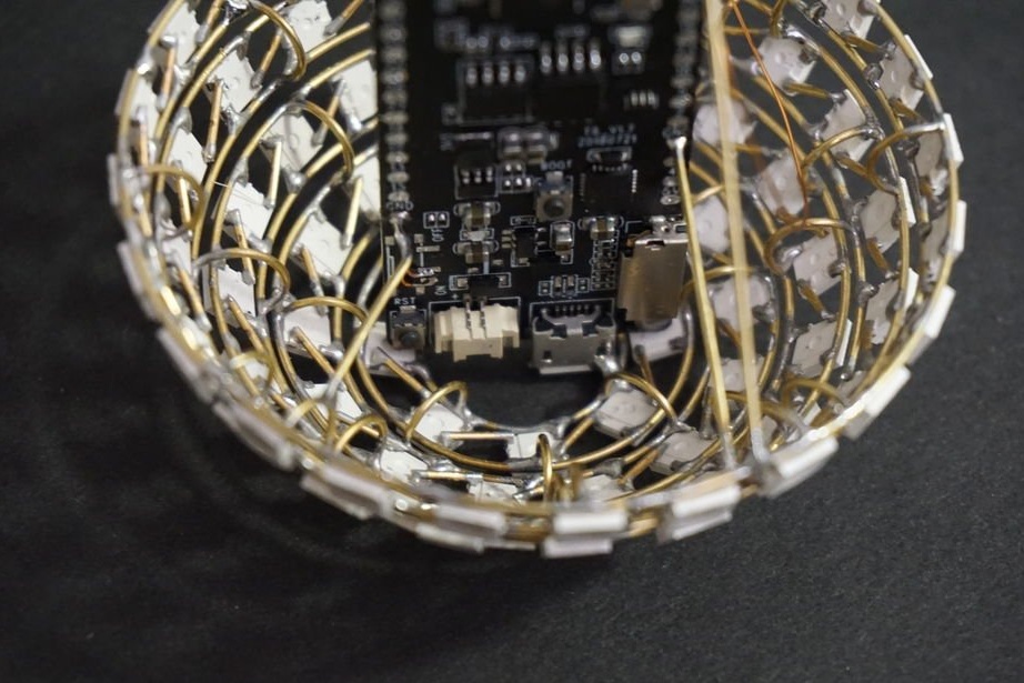
Next, you need to place the board in the smaller hemisphere so that the USB and battery connector is directed out of the sphere through the smallest ring. Solder a piece of wire between the corner and the lower ring. He pulls the two wires of the switch through the hole and solders the previously soldered switch to them. The switch has a metal case, solders it to a small ring so that it is accessible, but it does not interfere with the ball rolling. Be careful not to short-circuit the wires.
Next, you need to take a piece of straight wire and solder it to the 3.3 V pin on the ESP32 board. Then solder the other end to the last (plus) ring of the sphere. The master also strengthened the internal structure by soldering several pieces of wire between the ground rings and the terminals of the GND board. Next, you need to connect the main DIN pin to the IO21 pin of the ESP32, connect the battery and check the operation of the device.
If everything works, you can attach the battery with glue to the back of the ESP32 board.
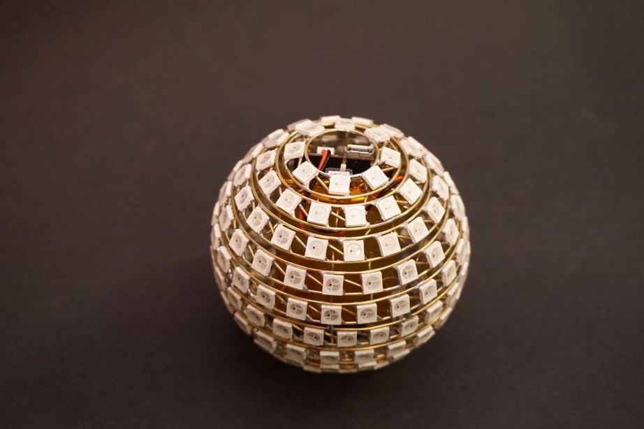
Step Six: Final Assembly
Now you need to ground it, add a short wire between the mounting holes of the ESP32 board and the nearest GND pin of the board - this will provide grounding for the second hemisphere.
Next, solder the jumpers connecting the DOUT of the first hemisphere to the DIN of the second hemisphere. Cut the wires 2 mm long and solder them to the upper ring of the second hemisphere.
Seventh step: code
Now you need to upload the file. ino for the project Arduino IDE The wizard uses the https://github.com/Makuna/NeoPixelBus library to control the LED strip. It has a nice interface and animation support.
To be able to control the animation, he made a table of 11 rows and 26 columns. Thus, it is precisely known how the LEDs are located on the sphere, and it is possible to light up exactly the LED that is needed.
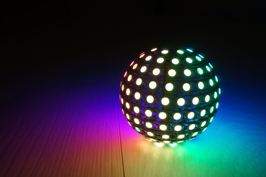
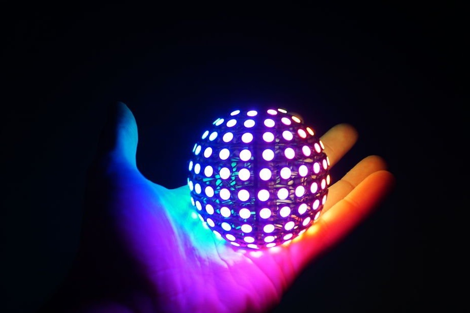
There are currently several animations:
vertical circle
horizontal circle
vertical rainbow
horizontal rainbow
rainbow
random picture
The master had to limit the brightness of the LEDs to about 20% of full power. The LEDs are 194, and at full power they consume 10A.
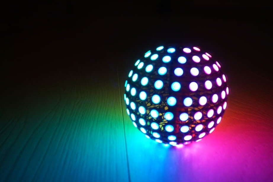
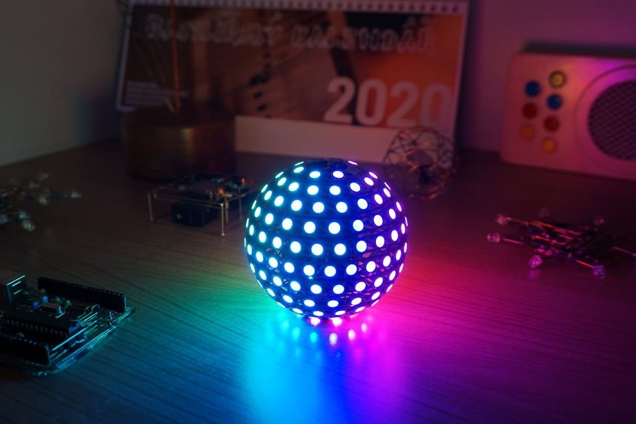
All is ready.
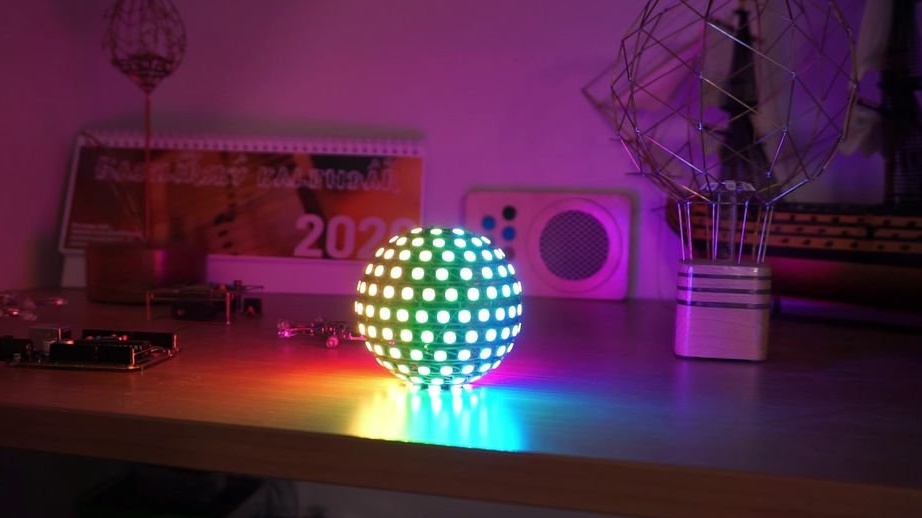
The whole process of manufacturing such an LED sphere can be seen in the video.