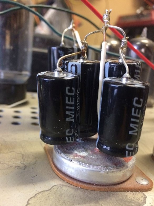
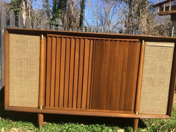
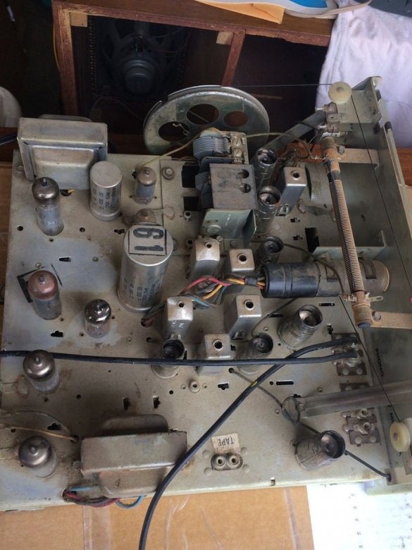
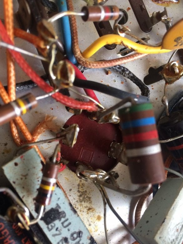
The author of Instructables under the nickname 2nup350 in a tube radio received an amazing quadruple electrolytic capacitor. All four sections in it naturally dried up, which is why during operation of the device a noticeable “background” was heard (it is clear that it is not radiation). An ordinary, single capacitor can simply be replaced, here you first need to figure out what to connect to.
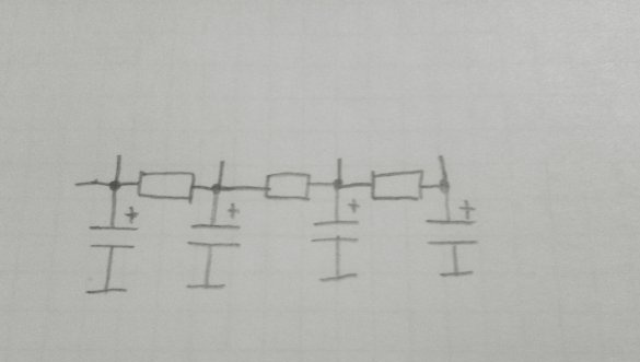
First, a small educational program, why such a capacitor is needed at all. There is more than one filter capacitor in any rather complicated tube device. To power its cascades with various voltages, as well as reduce their influence on each other, apply the circuit shown below. Cascades feed from bends. While the lamps are not warm up, there is no load, and the voltage at the taps is the same. A load appears - the voltages become different, the farther from the entrance, the less that is required.
Single capacitors in such circuits are most often found, but to make the devices more compact, the developers used double, built, and very rarely, quad capacitors. Now the need for this has disappeared, since current electrolytic capacitors are compact with a sufficiently large capacity. So in modern lamp combo filter capacitors are separate. You can not say about that vintage radio, which the master has to restore.
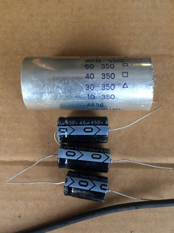
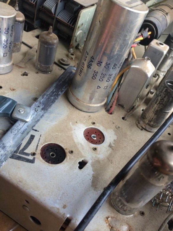
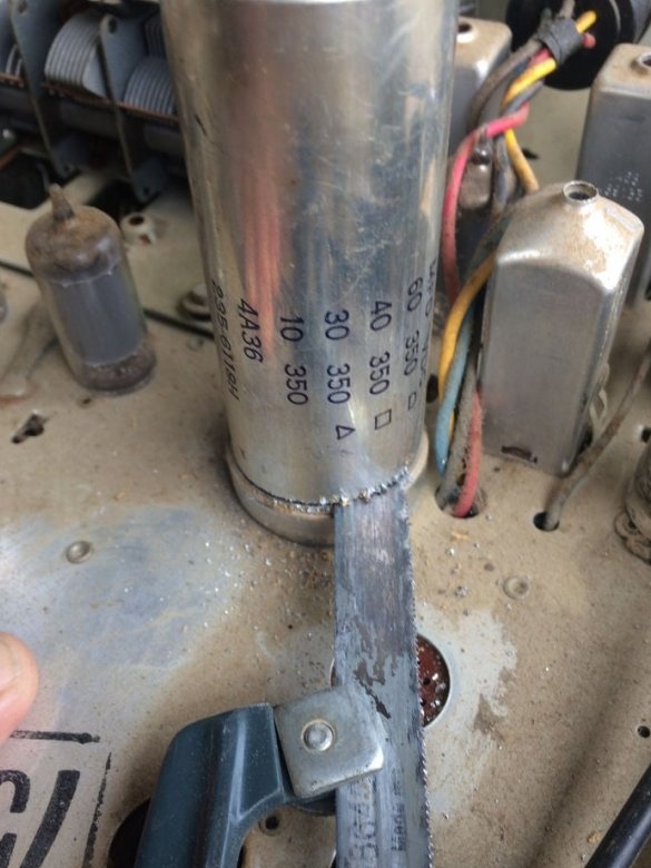
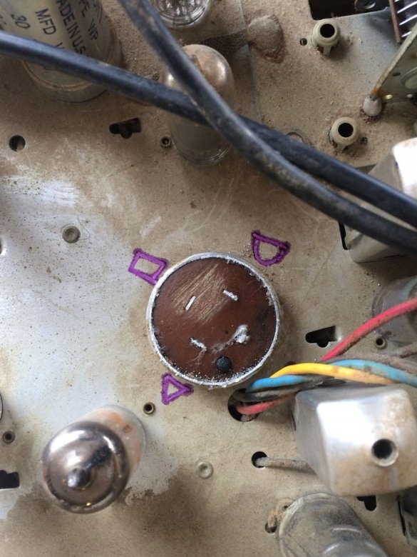
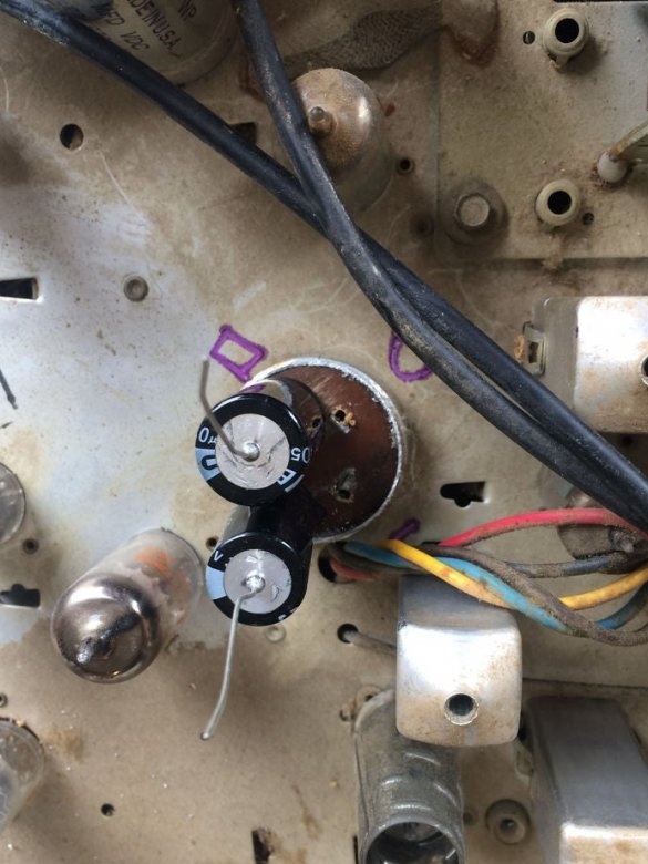
Let's look at the quad capacitor near. Its sections, whose capacities are different, are indicated by various geometric figures: a semicircle, a rectangle, a triangle and a space, if it can also be considered a geometric figure. Well, almost the designation on the buttons of the PlayStation joystick, which then was not yet in the project, almost.
Of course, all sections of the capacitor lost both capacity and EPS, but after turning off the receiver, the master still discharges them to the resistor, without touching its conclusions. And then he takes a hacksaw, and ... as the video blogger Kokovin says, "outEntality is spent." One lamp has to be removed for a while, so as not to hurt.
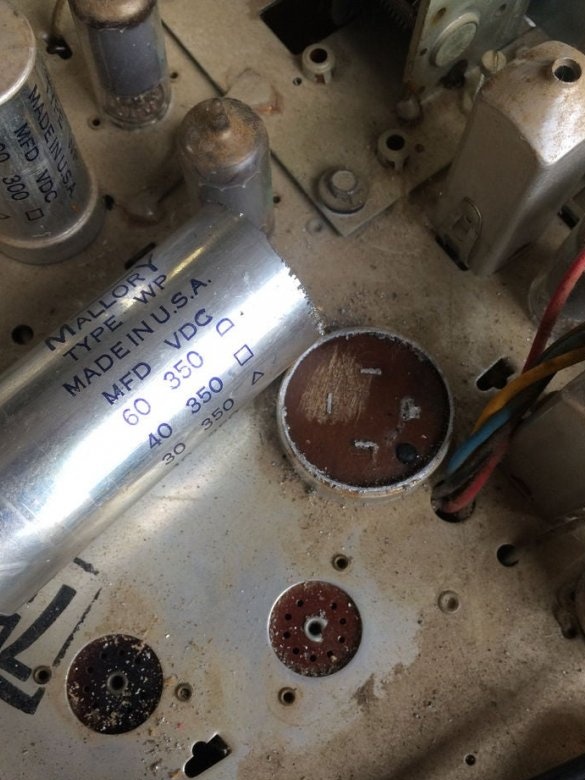
Everything is cut down.And there is epoxy. And here is what:
The capacitance of the capacitor sections, as it befits them, decreases: a semicircle - 60, a square - 40, a triangle - 30, and a space - 10 μF. Cons are connected together and connected to the chassis, and the pros are brought out. The voltages withstood by the sections are the same: 350 V. This is the maximum that appears in this unit while the lamps are cold and there is no load. But there is one caveat: earlier on the capacitors indicated the operating voltage, now - the maximum. New ones must be taken with a margin, the master chooses 450 V.
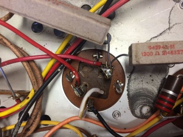
Well, on the case it’s clear where the geometrical figures are, and on the conclusions where? And they are not on the conclusions, but next to them, on the reverse side, right on the epoxy:
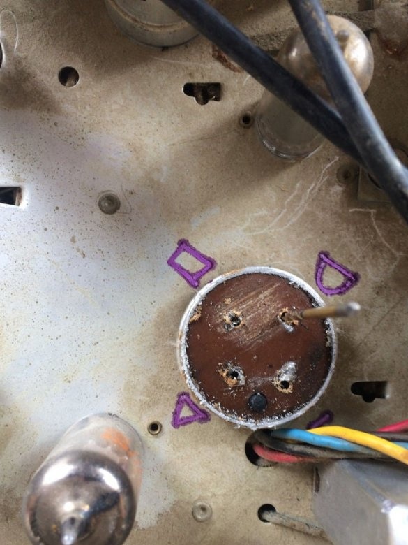
The master transfers the figures to the front side of the chassis, carefully following to avoid mistakes anywhere:
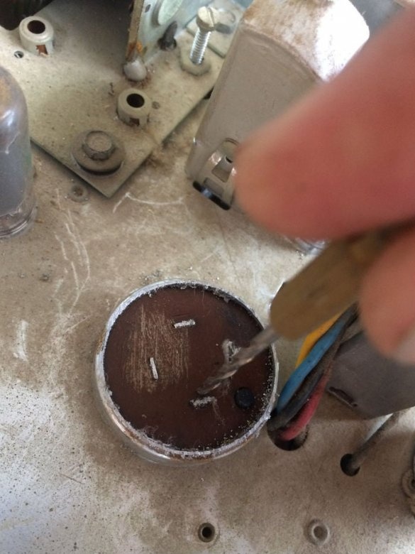
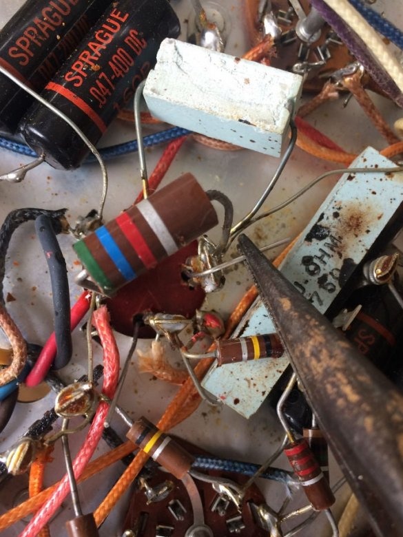
It drills the contact pads in order to pass the positive leads of the new capacitors down, and solders it from below.
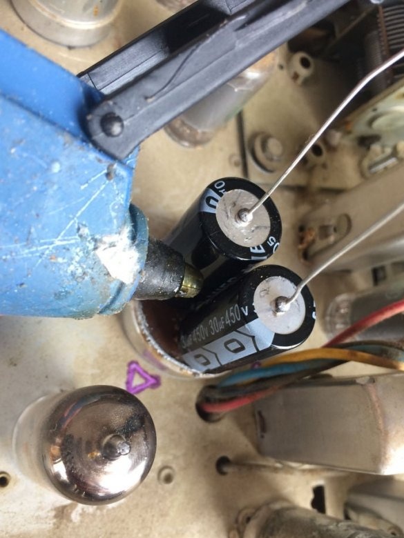
Combines the negative terminals of the new capacitors and connects to the chassis:
But hot glue, as shown below, it is better not to stick capacitors. Nearby lamps can melt it. Yes, and capacitors do not need additional fixation, they will not move much. Please note: the lamp, removed earlier, so that it does not interfere with sawing off the old capacitor, the master has already returned to its place.
The sawn off part of the old condenser can be stored in a desk drawer as a vintage item. Check the solder polarity of all new capacitors and test the amplifier or receiver in action. If everything works out, the AC background will almost disappear.

