Many friends use computer PSUs as laboratory ones. Sometimes with a redo for smooth adjustment, sometimes without it. In the second case, opening the PSU is not required, but the set of voltages is fixed. For convenience, you can add an external case with clips.
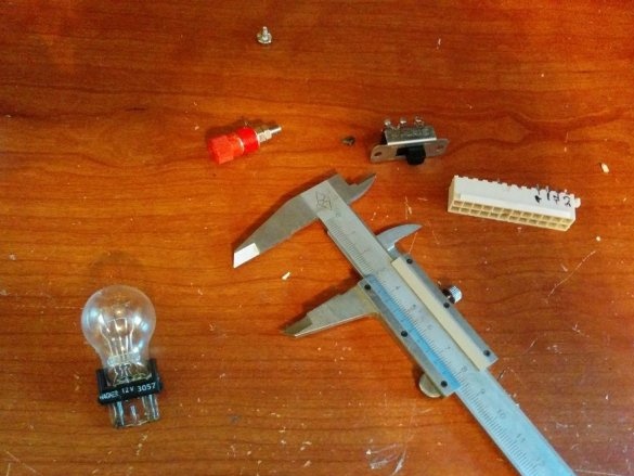
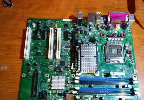
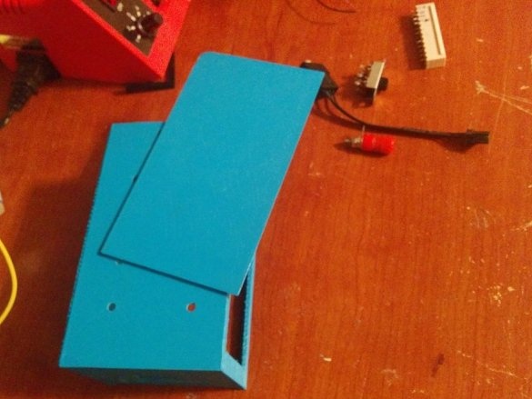
The wizard acquires the necessary components: clamps (only one is shown), a switch, a connector removed from a broken motherboard, a small car lamp, necessary for some PSUs, unable to work without load.
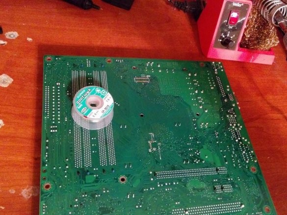
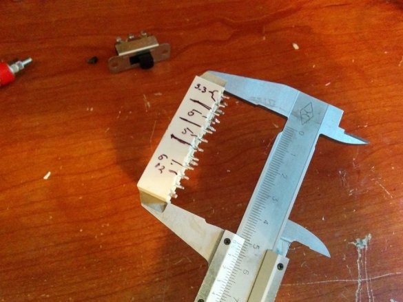
Here, the master solders the connector from this board:
Marks according to the pinout:
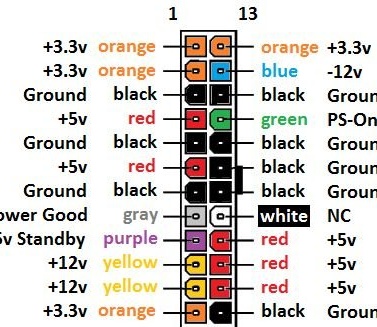
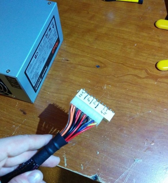
Connects to the output cable of the power supply unit:
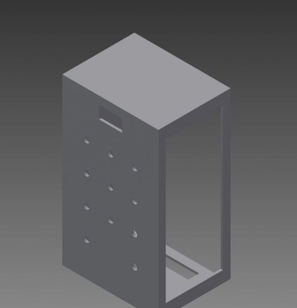
He designs a housing in which holes are provided for clamps, a switch, a fan, and the like:
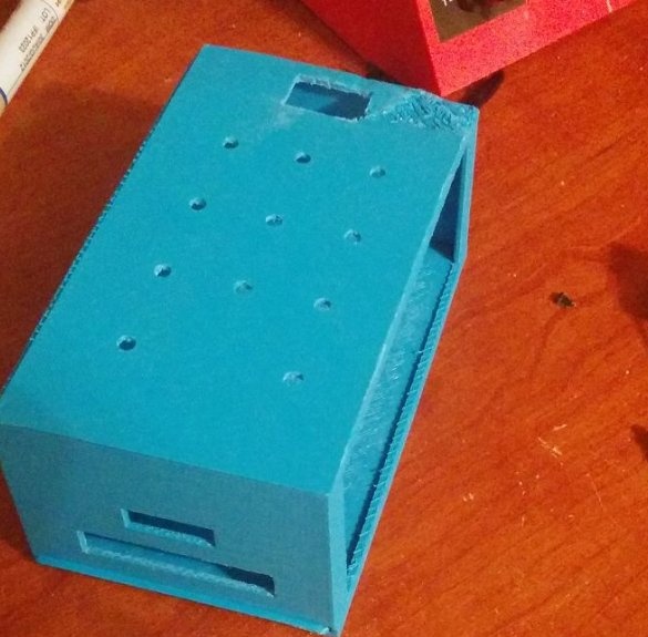
It prints a separate case and a separate cover, since at the same time they do not fit on a 3D printer table.
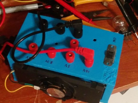
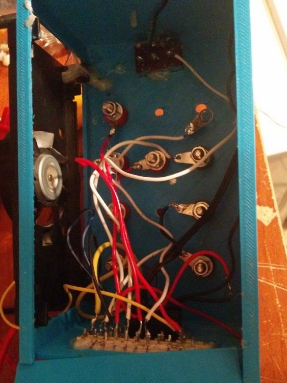
And it starts to connect everything. It displays all the voltages generated by the power supply unit onto the clamps with conductors of sufficient cross section, and also duplicates the common wire several times. A switch connects between black and green conductors. At the same time, the current flowing through the switch is small, since the control of switching on the power supply electronic. To turn off the power supply completely, including the standby power supply, you can use the switch installed directly on it, or disconnect it from the network. Attaches an incandescent lamp, necessary if the PSU is not designed to work without load, as well as a fan to cool this lamp.
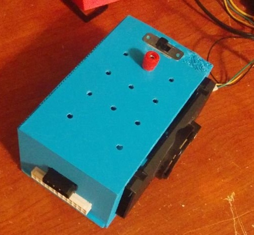
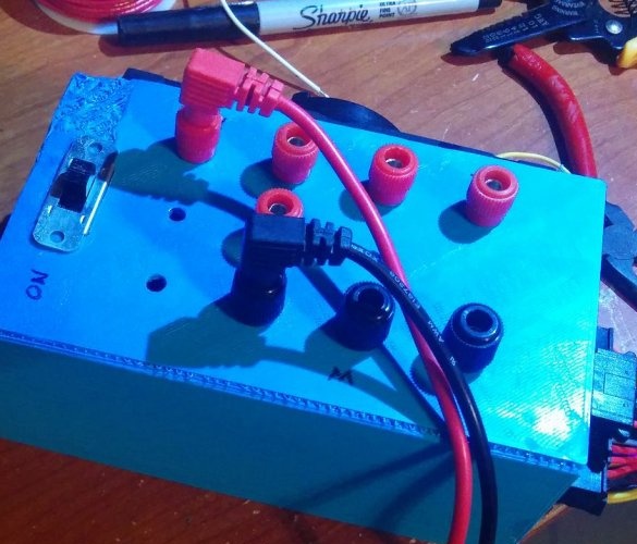
Homemade ready. Due to the fact that the master does not bite the power supply connector from the PSU, you can rearrange it to the computer if necessary.

