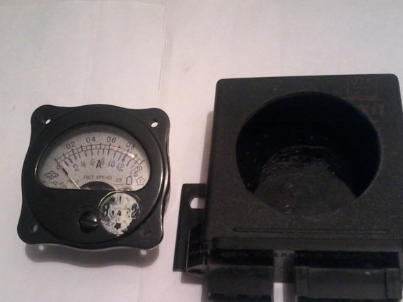
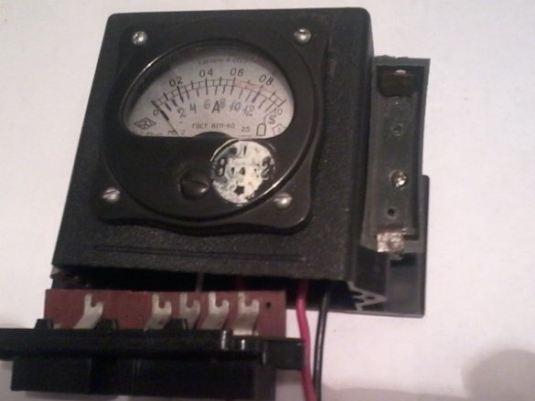
Hello, friends the inhabitants of our site and site visitors! I bring to your attention a device that every car owner needs. This is a probe for monitoring the electrical equipment of a car. They can determine the state of the battery, check the voltage regulator, the condition of fuses, relay windings, the presence of voltage at any contacts of the car, the integrity of the wiring, check the health of the capacitor, and much more.
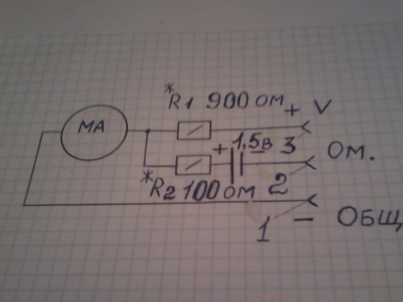
The device diagram is shown in the photo.
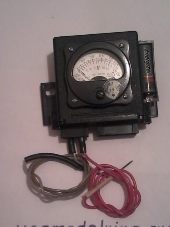
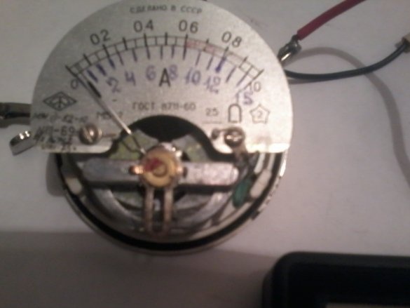
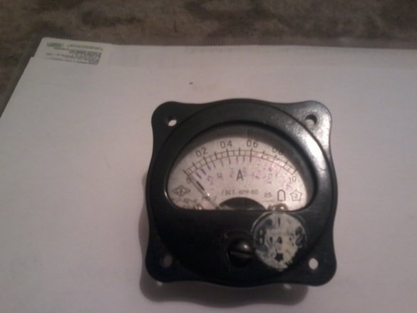
It consists of a milliammeter with a scale of 10-15mA, two resistors R1 and R2, a 1.5V battery, three plug connectors for connecting test leads, and a housing in which all these parts are located. Using test leads connected to connectors 1 and 2, you can measure the resistances and integrity of the wiring. And having connected to sockets 1 and 3 - we measure voltage in a car network. The scale of the device is calibrated with a measurement limit of 1 V, and plotted under the main scale.
To assemble the homemade product, we need the following parts and tools.
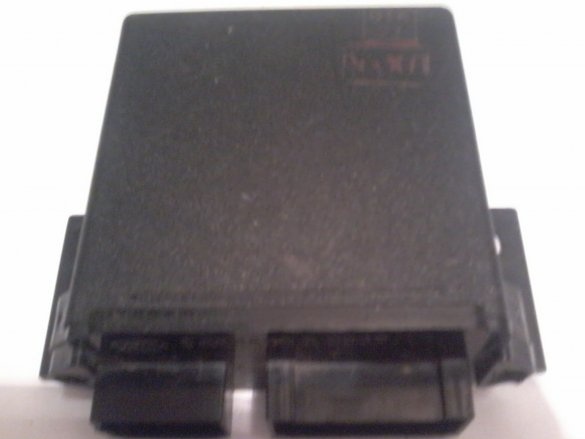
It: The housing is from a PC951A automobile relay, a milliammeter with a 10-15mA scale, an MLT resistor of 0.5 W-900 ohms -1pcs, and 100 ohms - 1 pc. Resistors are selected when setting up the device, and can vary greatly from those indicated in the diagram. 1.5-volt battery, 3-pin connectors, mounting wires, small battery case.
Instruments: soldering iron, solder, tweezers, pliers, nippers, drill, drill, round file, M-3 screws and nuts, multimeter, power supply from 1 to 15 in.
We begin assembly homemade.
Step 1. We disassemble the milliammeter case, remove the measuring head from it.
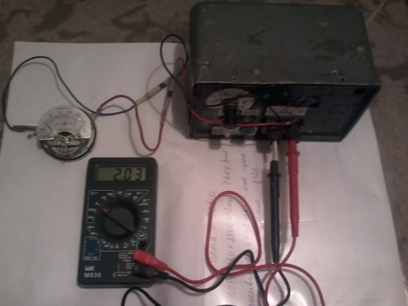
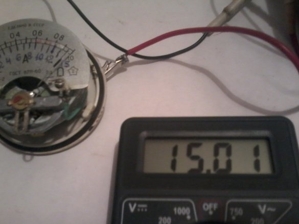
We connect to the head clamps a power supply with a voltage of 15 V.
We connect the plus of the unit through a 1 kΩ variable resistor, and in series we connect a 470 ohm constant resistor to this resistor. Rotating the handle of the variable resistor we achieve the deviation of the arrow of the device by the final division of the scale.
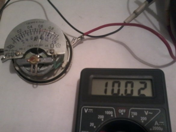
Then, having measured the resulting resistance, we set a constant resistor instead of a variable.Then, connecting in turn the voltage from 1 to 15 V, we calibrate the scale of the device by applying a new scale, placing it under the existing one, after 1 century.
Step -2. We select the resistor R2, connecting instead a variable resistor of 1 kΩ with a 47 ohm resistor connected in series with it. We close the connectors 1 and 2 together, rotate the handle of the resistor, we achieve the deviation of the arrow of the device to the final division. Then we put a constant resistor instead of these two. Then, you can also calibrate the scale for measuring resistance, connecting in turn to terminals 1 and 2 resistors at 2 com, 4 com and 6 com, apply the corresponding marks on the scale. This device can measure resistance from 0 to 6 com. I did not do this, because I am quite happy with such a scale.
Step -3. We remove all the insides from the existing PC951A relay case, except the input connectors, I used them instead of the input terminals.
In the case we mark a hole for a milliammeter, cut it out. Then we install the battery case and the device itself.
Step 4. We solder according to the resistors selected by us the entire circuit of the device. We fix the device in the case, and the outer cover, we make measuring conductors. We check the device by connecting any wire to sockets 1 and 2, and make sure the arrow deviates by the final division of the scale. We connect any battery to connectors 1 and 3 and measure its voltage.
The device is ready, now it can be transported in a car, and believe me, it is necessary in a long journey.
I wish you all good luck in your work.
Happy New Year! See you again.


