
a master from Norway likes the way to determine the time with binary code. Surprisingly, the amount of information can be displayed in simple ON / OFF signals. Then the master decided to make a binary clock on his own.
Tools and materials:
- LEDs 0603 - 13 pcs;
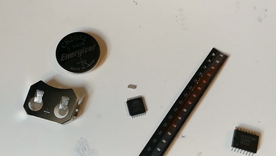
Microprocessor Atmega328P-AU;
Capacitor 0806 0.1 uF;
-Tantalum capacitor 1206 4.7 uF;
- Resistor 0806 10 kOhm;
- Real-time clock module DS3231;
-0806 resistor 51 kOhm - 3 pcs;
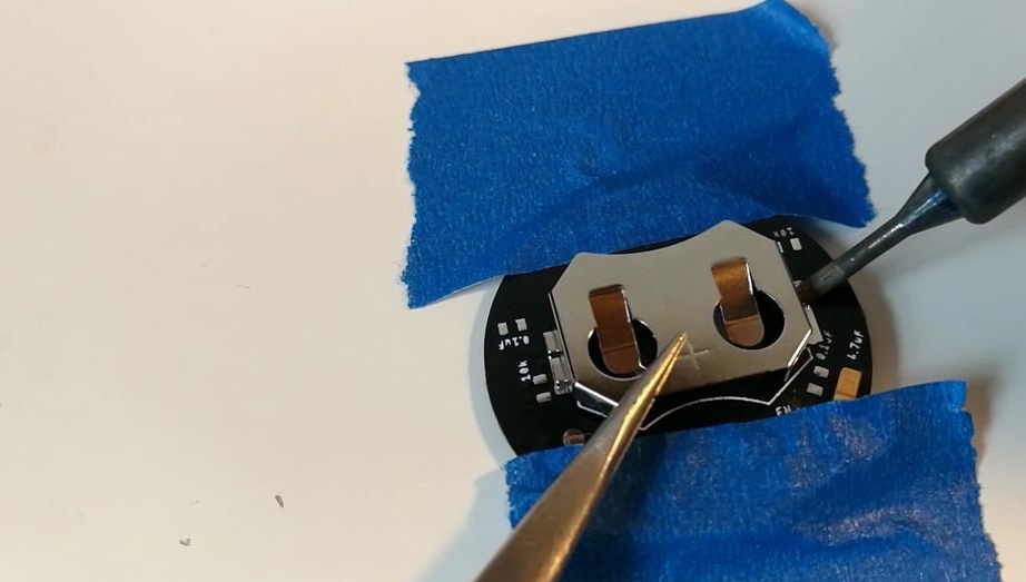
-SMD battery clip CR2032;
-CR2032 battery;
-4.5 mm button;
-0806 resistor 200 Ohm;
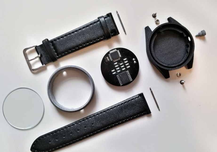
-20 mm watchband;
-20 mm spring level - 2 pcs;
-Glass 38 mm;
-5 cm (2 inches) of thin winding wire;
-2 screws M2 with a flat head 6 mm long;
-2 nuts M2;
USB-TTL adapter
-Soldering accessories;
-Tweezers;
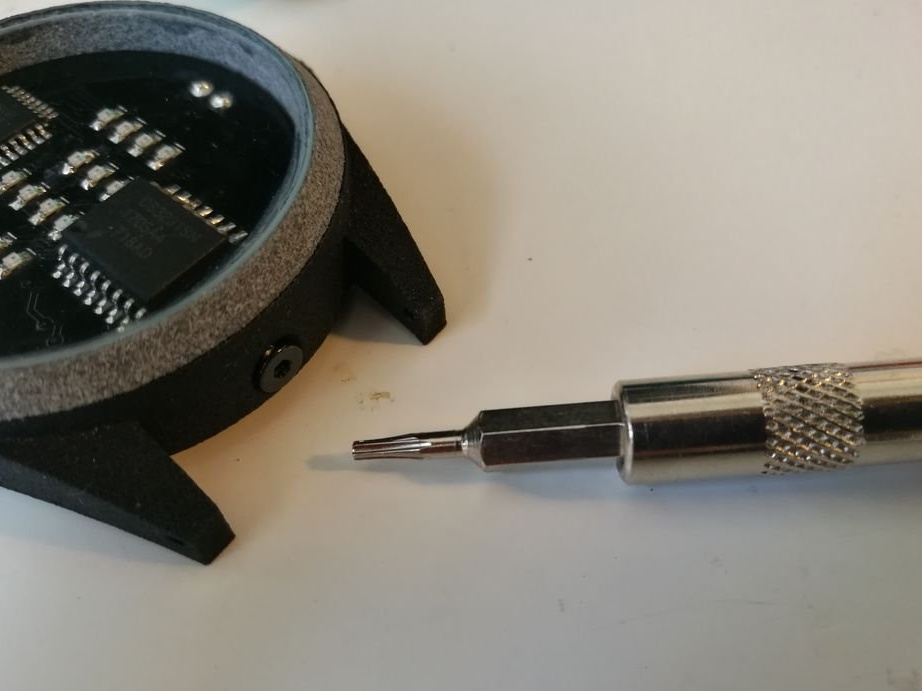
-Small screwdriver;
-Access to high-quality 3D-printer;
Step One: Design and Customization
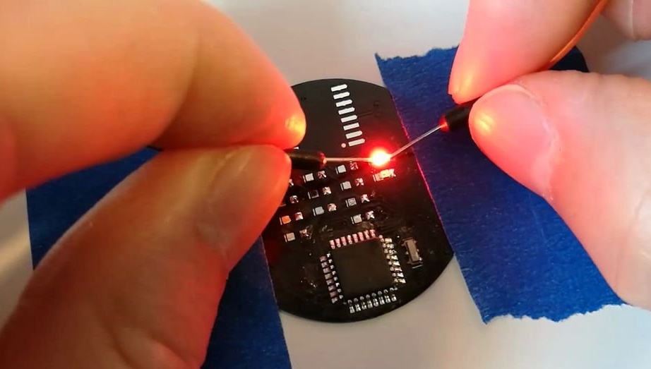
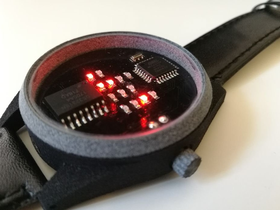
The watch has 13 LEDs located in a multiplex matrix. One column corresponds to one digit in digital time. The time is displayed in binary decimal format, and one digit is represented by a maximum of four bits.
They look stylish and work great thanks to a simple user interface and a battery life of up to two years.
The design, when the watch is turned off, is a simple two-tone combination of black and silver. These colors are present in the leather strap and clasp, as well as on the case and on the printed circuit board.
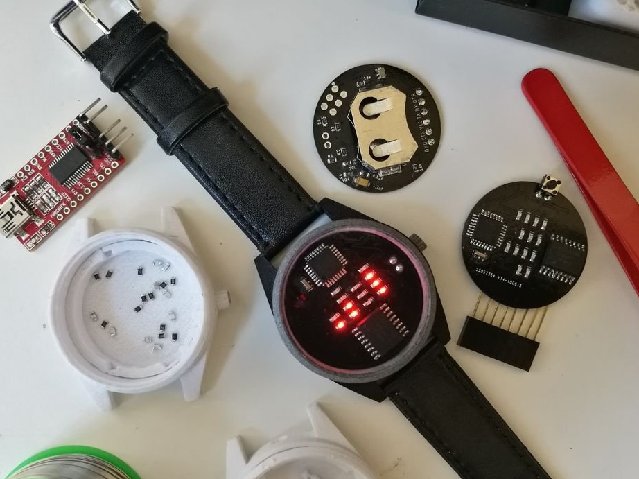
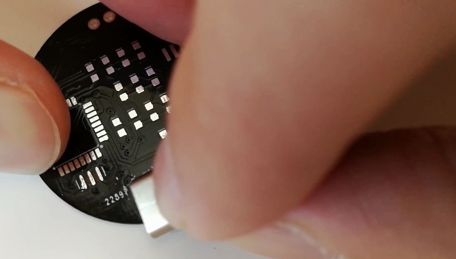
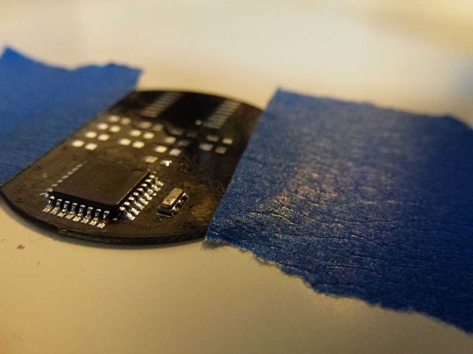
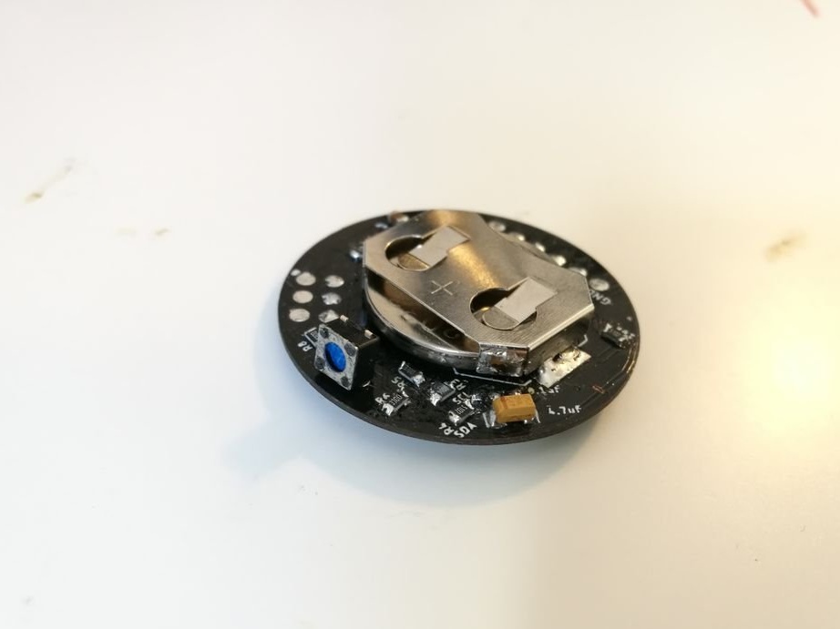
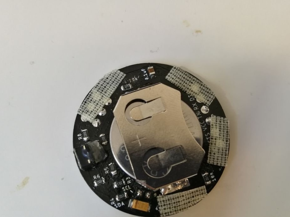
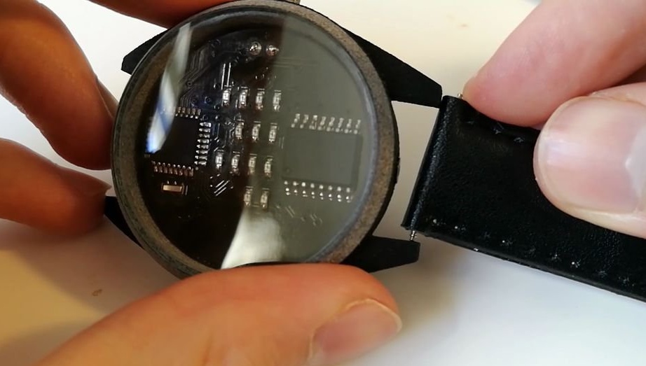
The wizard hid most of the components on the back of the circuit board and made it with a black background. Electronics and the circuit board matches the two-tone design of the watch.
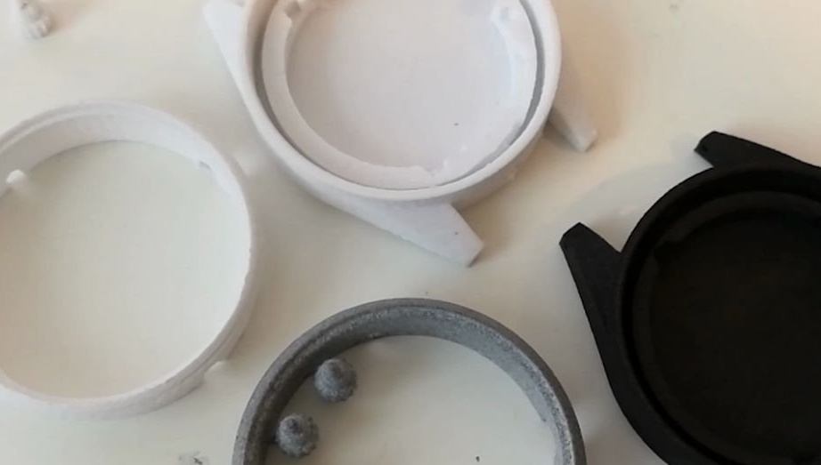
The watch case must be durable, but it should be easy to open to replace the battery or make changes to the code. This means that no glue is used during assembly. The only detail on the glue is glass.
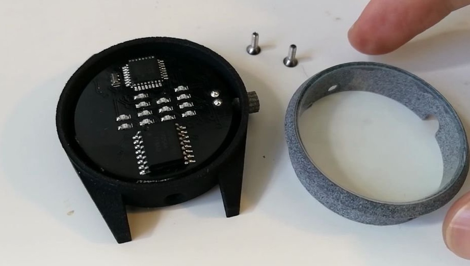
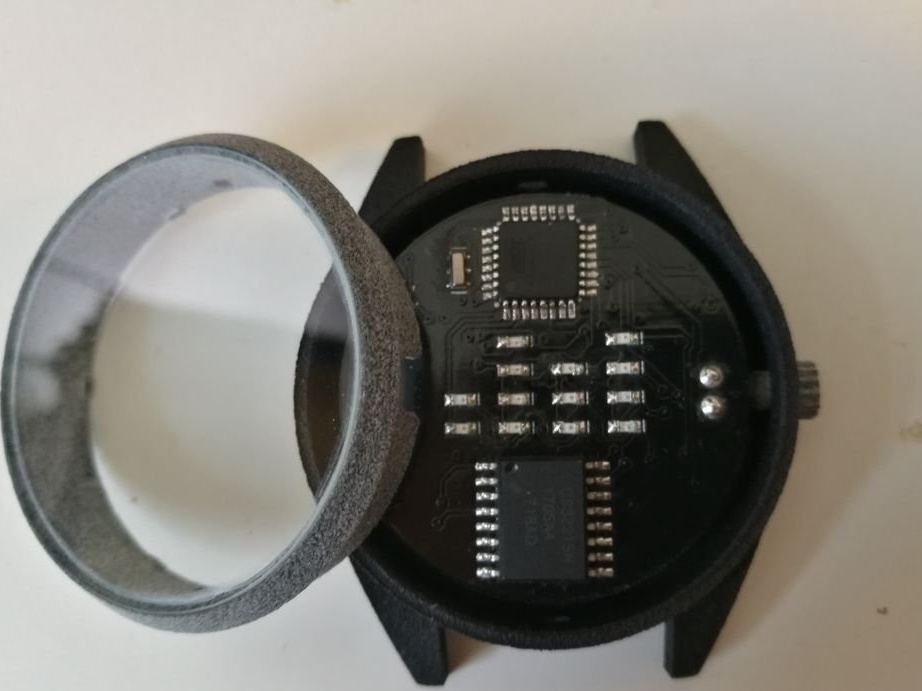
The case consists of two parts of the lower part and the ring. A printed circuit board, a watchband and a crown are installed on the bottom of the watch. A glass is mounted on the ring.
Much attention is paid to energy consumption. In deep sleep, the watch consumes only 10 μA. This gives a battery life of more than two years.
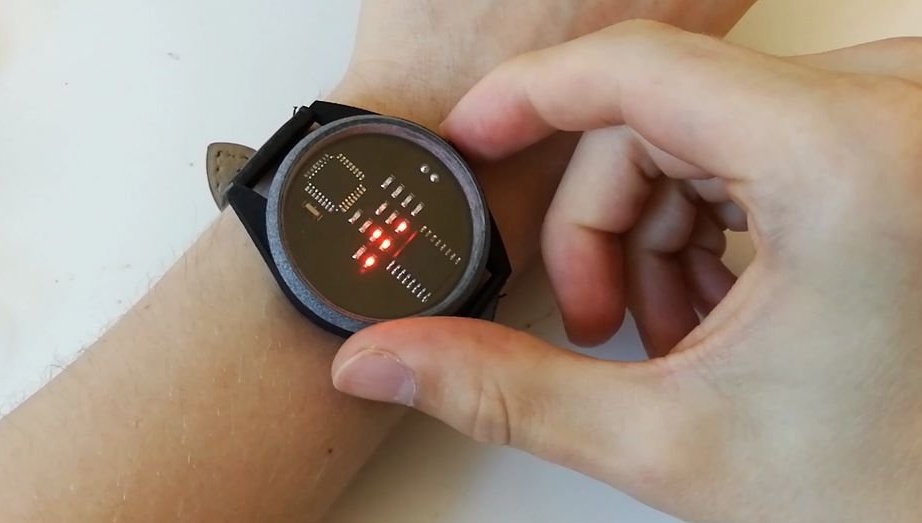
As for the user interface, you just need to press the crown of the watch to wake them up and they immediately show the time. When you press the button again, the date will be displayed. Since the battery life is two years, you can easily switch between summer time without connecting to a computer.To do this, press the button 15 times in a row.
Step Two: Component Selection
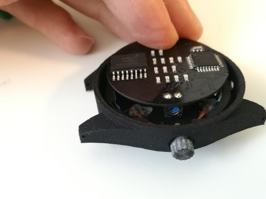
There are four main parts to a circuit board. Microprocessor atmega328p. This is the same as in popular models. Arduino. This is the brain that will communicate with the real-time clock (RTC) module, process the time and display it using LEDs. All this, of course, needs a power source, preferably a tiny battery.
ATmega328P
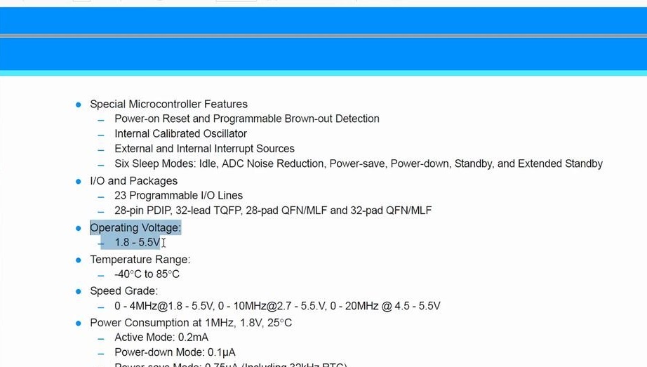
The microprocessor had to meet certain criteria. GPIO required at least nine pins, eight for LEDs and one for a button. He also needed an I2C bus, where he could act as the master device for polling RTC at the moment. Finally, it had to operate at low voltages and not consume an excessive amount of current when powered. Atmega328P-AU meets all these criteria, and at the same time is small enough not to occupy the entire area of the printed circuit board. A big plus is that it is also used for most popular Arduino boards and many can work with it.
Printed circuit board
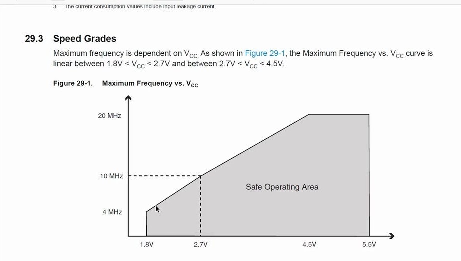
The board was designed to use an 8 MHz ceramic resonator. However, it turned out that the processor must operate at a lower frequency in order to operate at low voltages. Look at the image in this step, taken from page 303 in the datasheet, which explains the relationship between clock speed and operating voltage. The clock frequency of about 4 MHz should be the maximum for this project. The master used an internal 8 MHz oscillator and activated 8-bit division, which gives a visible clock frequency of 1 MHz. However, an 8 MHz resonator is still needed when loading the code. After loading, the wizard did not delete it
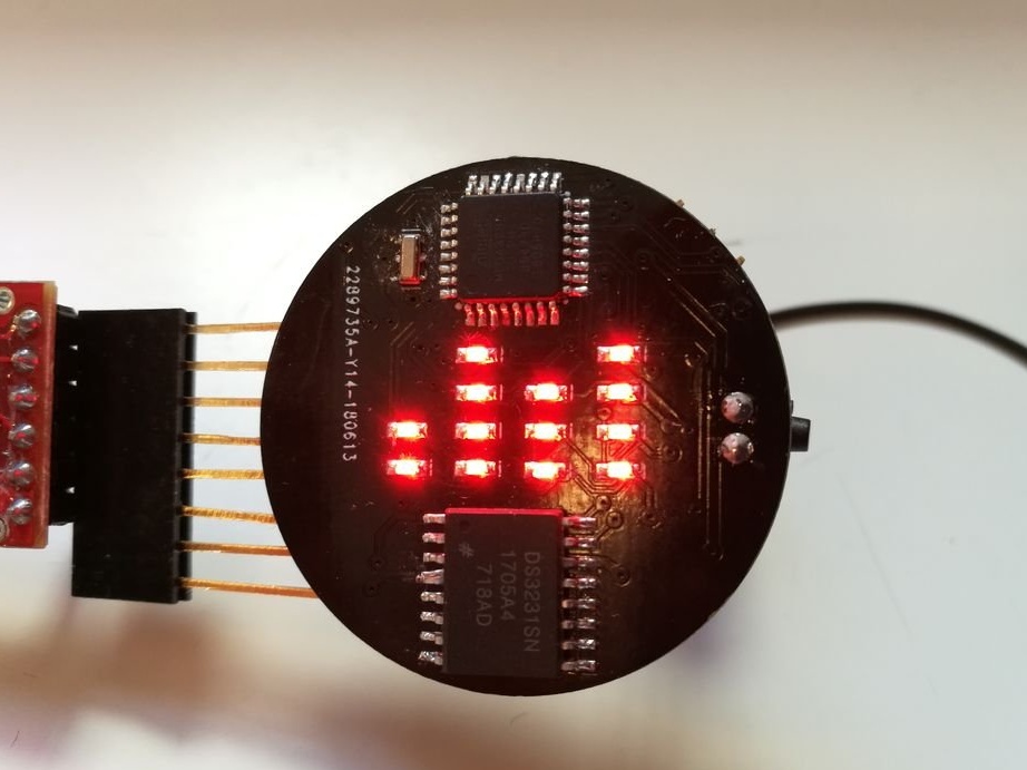
DS3231
At first, the master wanted to use the DS1307 RTC. This is a more popular chip. However, it requires a 5 V power supply.
The DS3231 can operate at a low voltage of 1.8 V. The chip has a built-in quartz crystal. The built-in crystal of the watch also has temperature compensation. Ambient temperature can cause irregular oscillations of the clock crystal. This means that it is becoming less accurate. The DS3231 measures the ambient temperature and uses it in the calculation to compensate for temperature fluctuations. Ideal for watches when you enter and leave different rooms or go outside when the temperature is not constant.
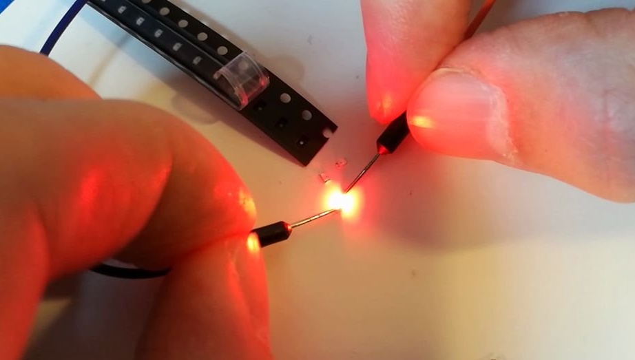
LEDs
The master uses LEDs of the 0603 form factor. They can consume up to 20 milliamps, but due to the fact that no more than three LEDs can work simultaneously, this is not a problem. The current also decreases when using resistors with a larger rating than necessary. The master says that it is most effective, for these LEDs, to use 100 - 400 Ohm resistors.
CR2032
The clock circuit can be powered by a lithium battery. She has no problem reducing voltage at the same current as the CR2032, but this will bring additional problems. For this project, a lithium-ion battery will have two main drawbacks. The capacity of the tiny cell is close to that of the CR2032, but it requires an additional charge for safe charging and safe discharge. You will also need a way to connect the charger. Therefore, the master chose CR2032.
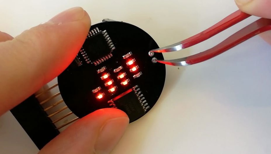
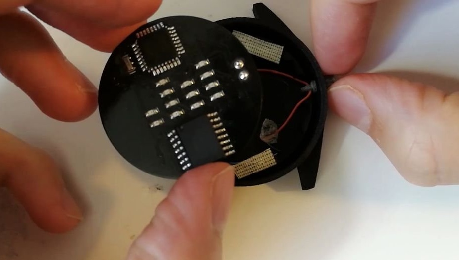
Step Three: Multiplexed Matrix
The configuration used in this watch is a matrix of 4x4 LEDs with the dismantling of three unnecessary LEDs.
Only different LEDs in one column are on at a time. This column is then disabled before activating the next column. All this happens faster than the eye can perceive. As a result, it seems that the LEDs in different columns are turned on simultaneously, creating a complex picture.
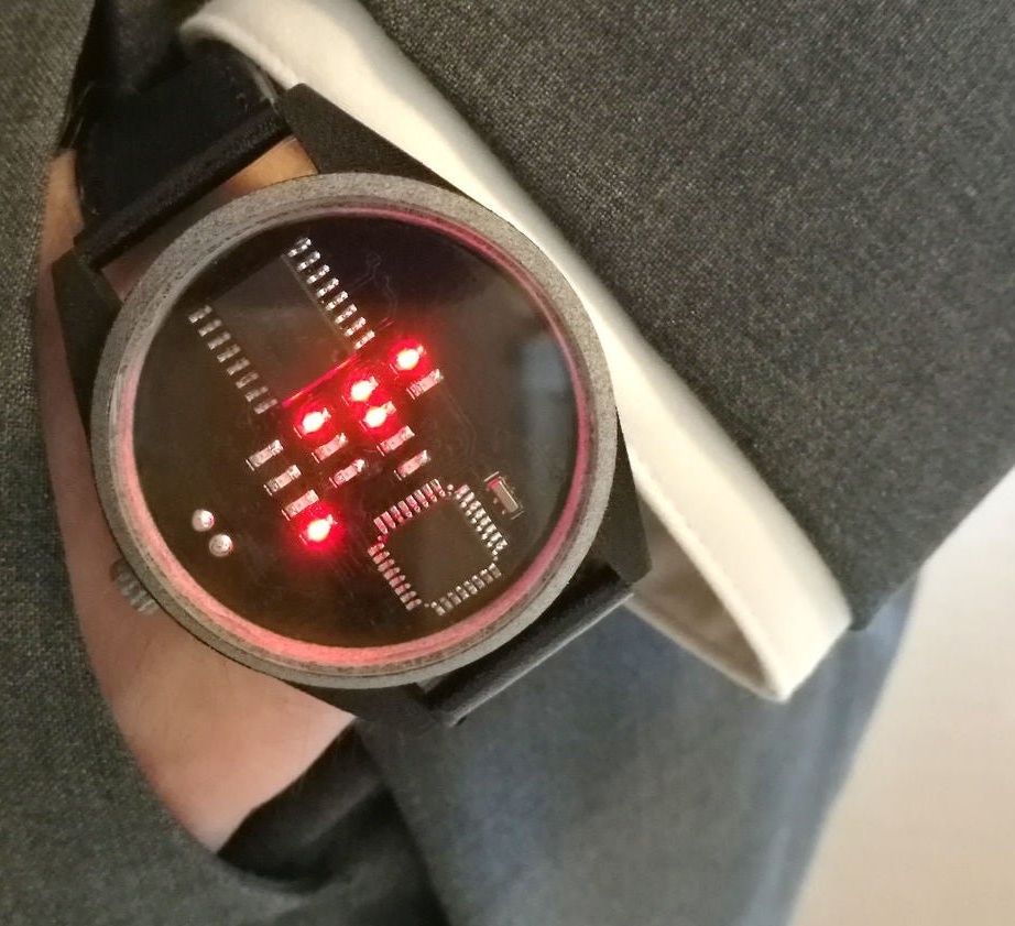
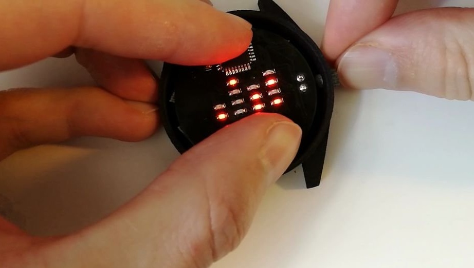
How can I find out what time it is by such a clock? Let's look at the pictures.
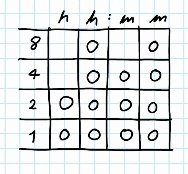
In the first figure, we see a 4x4 matrix with 13 LEDs. The rows of the matrix are numbered 1,2,4,8.
In order to find out the time, it is necessary to add all the LEDs in one row, then in the next, etc.
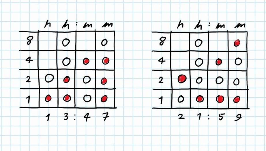
For example, Figure 2, the first square. From left to right, one LED lights up the first column, the first row. We have the first row under the number 1, which means the first digit of the hour 1. Next, the second column is lit by two LEDs under the numbers 1 and 2. Add up the numbers, it turns out 3. The next column is one LED number 4. And the last column is the LEDs 1 + 2 + 4 = 7 . We get 13 hours 47 minutes.
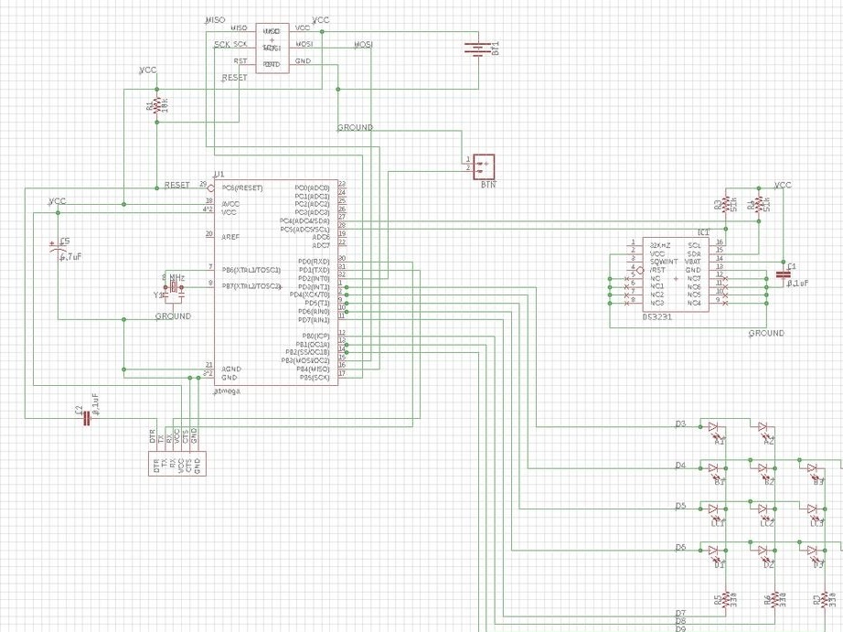
Step Four: Scheme
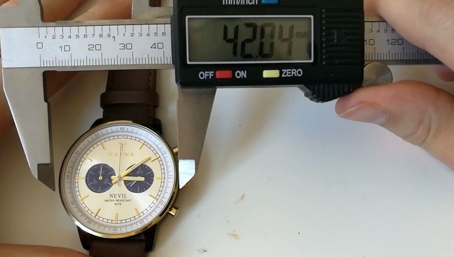
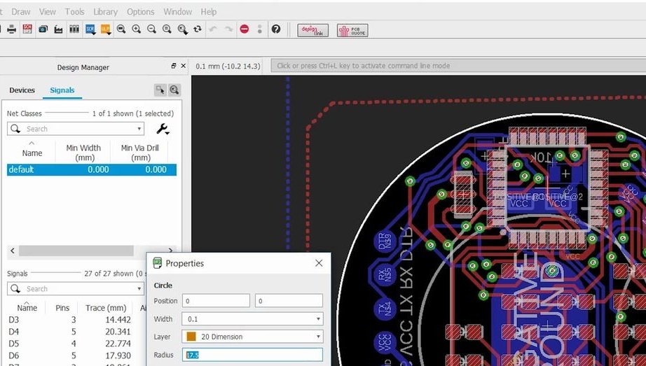
The circuit board has a round shape, like a classic watch. The standard watch case is usually 42 mm with a glass diameter of 38 mm. This is the outer edge of the glass. However, if the glass rests on an edge 1 mm wide, the available diameter becomes 36 mm. This meant that the circuit board should be about 35 mm.
The master ordered a fee on a well-known site. The boards have a thickness of 0.8 mm.
You can download the file for making the board below.
Binary Wrist Watch - GERBER.zip
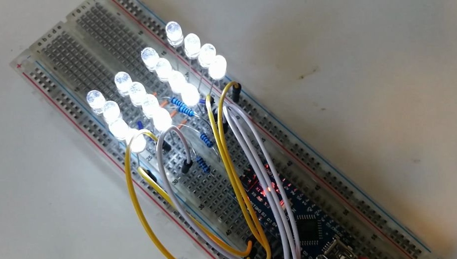
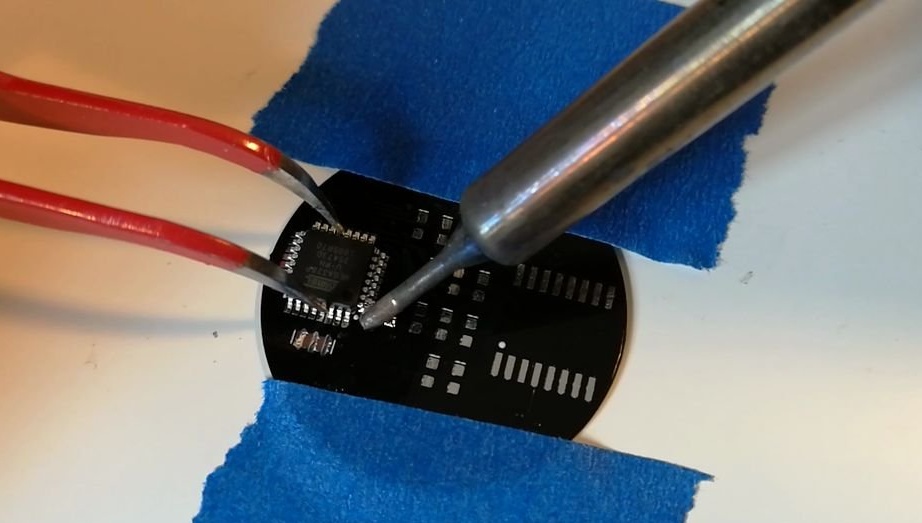
Step Five: Soldering
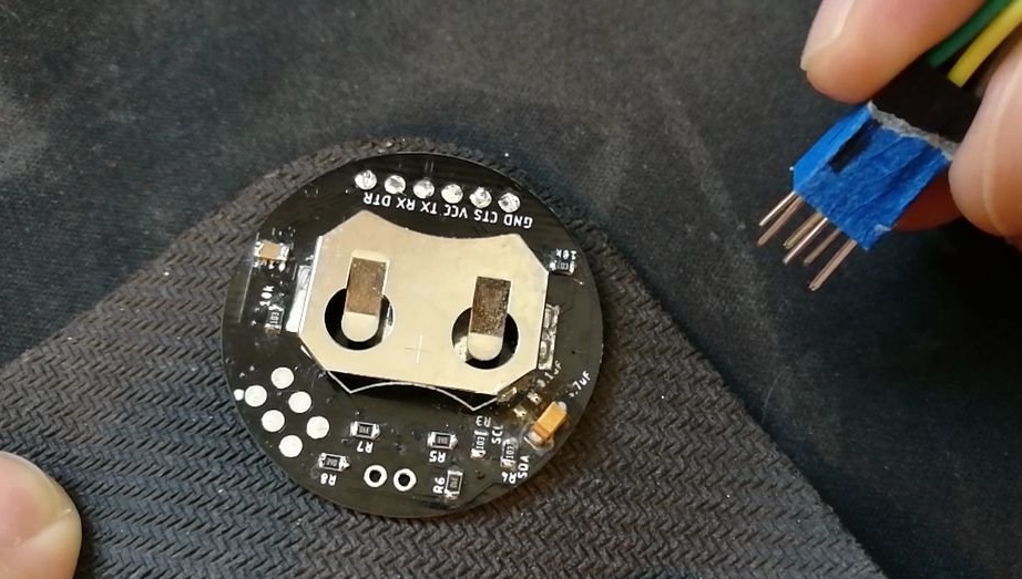
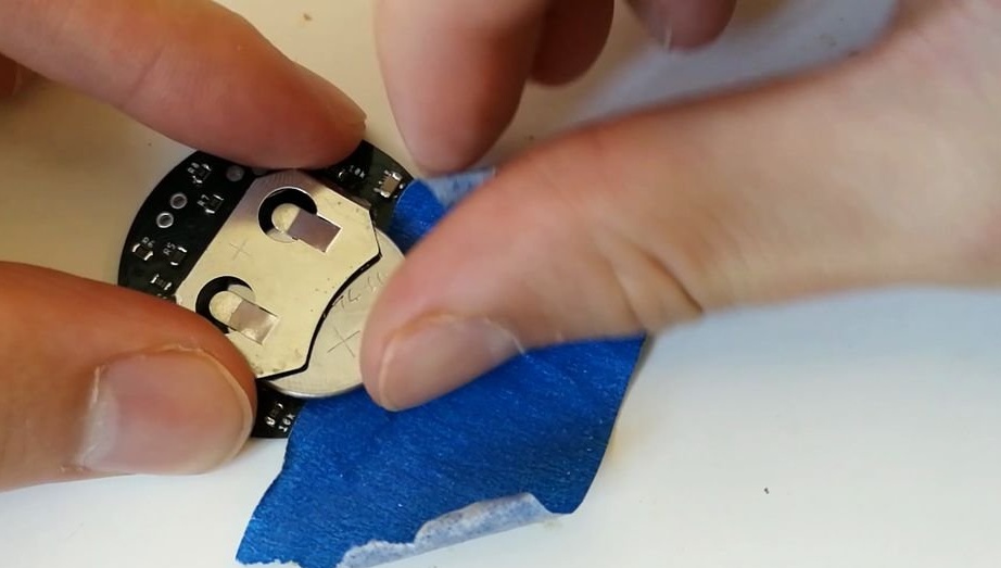
The best way to fix the circuit board during soldering is with masking tape. The master fixes the board and begins installation according to the diagram. First, the smallest components are soldered (in size).
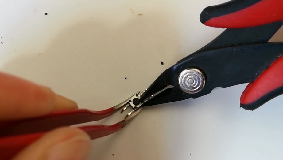
Step six: finalize the button
As you can see, the crown of the watch on the side of the case is designed, in this device, to control the watch. It interacts with a micro button connected to the microcontroller. To do this, the button needs to be redone.
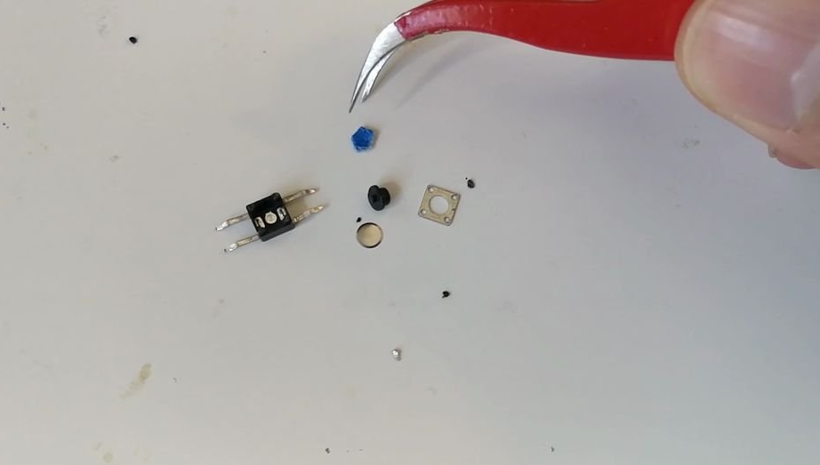
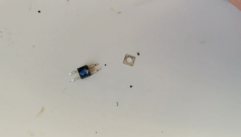
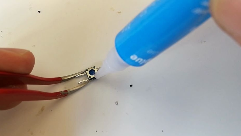
The cheapest tactile buttons have a small round black plastic part that you need to click on to close the contacts. It needs to be replaced. The master dismantles the button, cutting off the metal fasteners. Deletes a button. Sticks a piece of masking tape on a metal plate and sets it back. Glues the button body. Now you can solder the button.
Seventh step: coding
The microcontroller cannot work with the Arduino code at this stage. First you need a bootloader. This is a subroutine that must be stored on a chip in order to download and execute a written program.
Since it is an Atmega328P with extra low voltage, it requires a special type of bootloader.
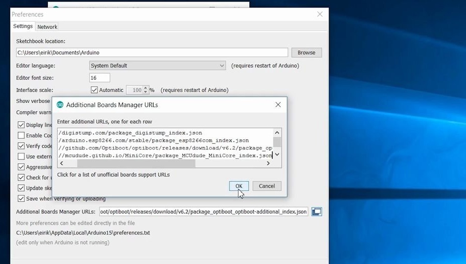
Open the Arduino IDE, choose File> Preferences> Add-On Board Manager URLs, and add a comma after the last URL before pasting the following URL
...
Click OK several times and go to Tools> Board> Board Manager. Open it, find minicore and install it.
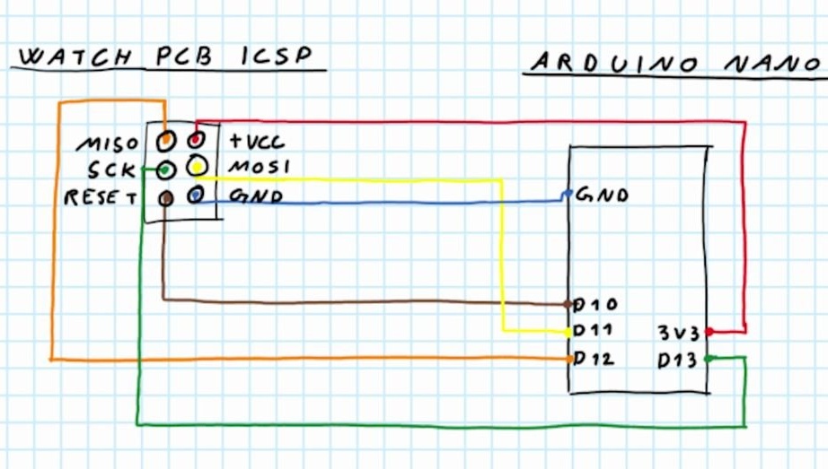
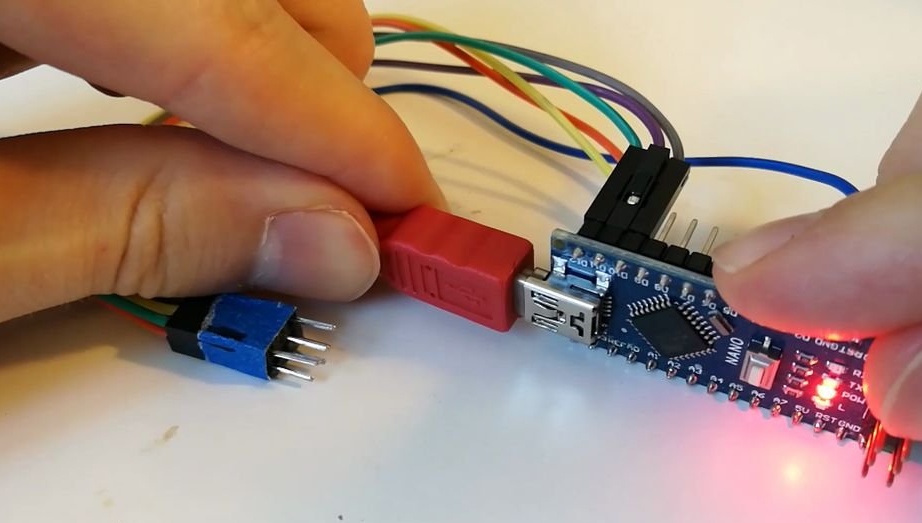
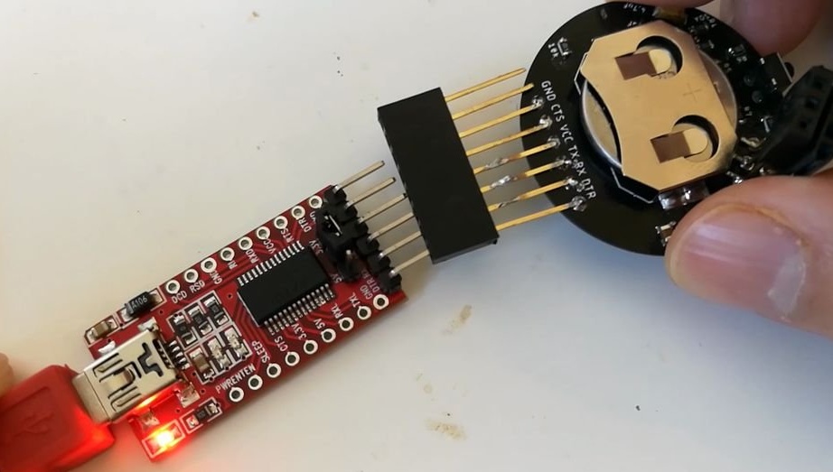
Connect the Arduino in the circuit as in the photo. Go into the Arduino examples and open the ArduinoISP sample code. Download the code.
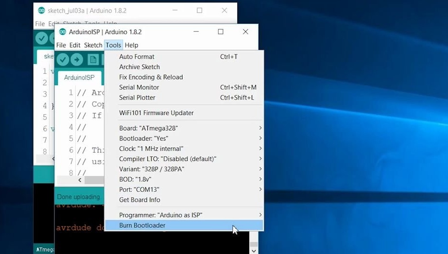
Next, install install Tools> Programmer: in "Arduino as ISP". Select the following configuration from the MiniCore bootloader. You can also double check your configuration according to the configuration in the picture attached to this step.
Bootloader settings
Board: ATmega328
Bootlader: yes
Clock: 1 MHz internal
Compiler LTO: Disabled
Variant: 328P / 328PA
BOD: 1.8V
Now the last step is to connect the wires from the Arduino to the watch board. Choose Tools> Burn Bootloader. Wait a moment and you will receive a message about the successful installation of the bootloader.
Now it remains to download the code. It can be found at the link below.
Binary_Wrist_Watch.ino
Step Eight: Case
The watch case was printed by a master on a 3D printer. Files can be downloaded at this link.
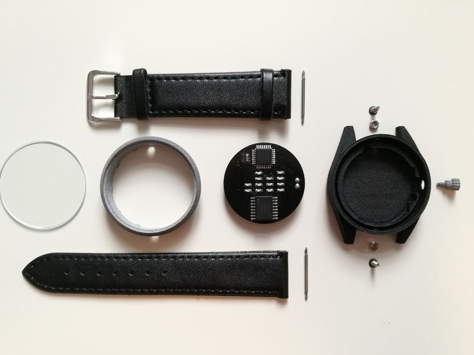
Step Nine: Build
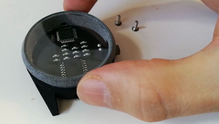
By now, all parts have been assembled, and you can proceed with the assembly.
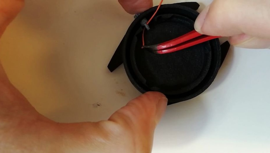
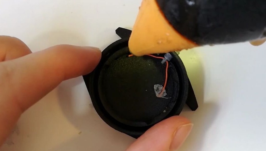
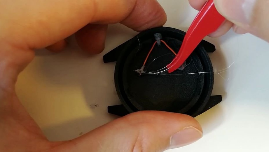
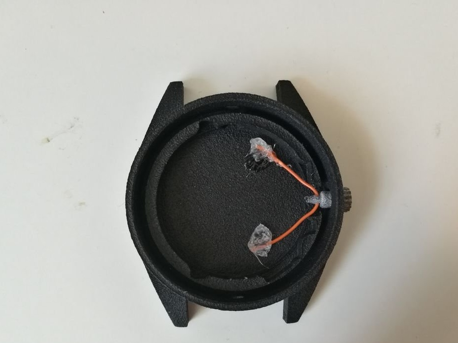
Insert the crown into the watch case.
Pull the wire through the mounting hole in the crown of the watch.
Glue the wire, making sure that the head can be recessed by 1 mm.
Insert the hex nuts into their corresponding hexagonal slots and fix them in place with a small piece of adhesive tape.
Attach double-sided adhesive tape to the underside of the circuit board.
Insert the circuit board, making sure the head pin is aligned with the button hole.
By pressing the head, check the operation of the button.
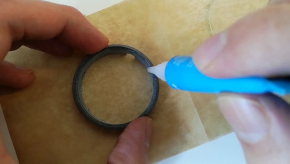
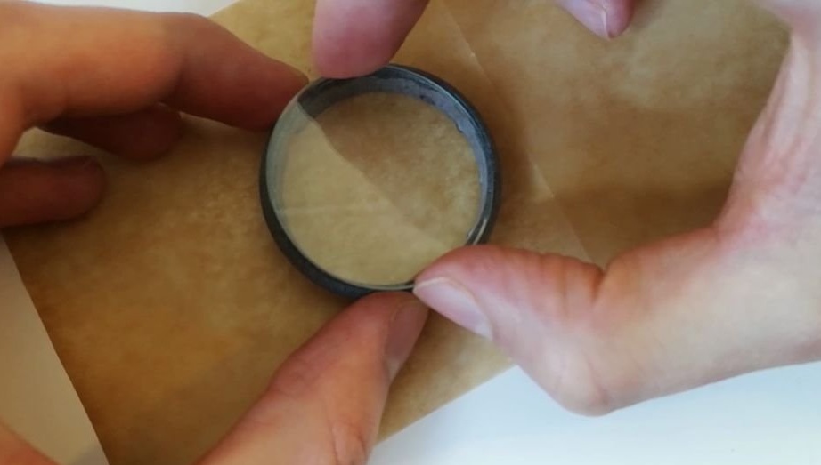
Glue the glass to the ring using superglue.
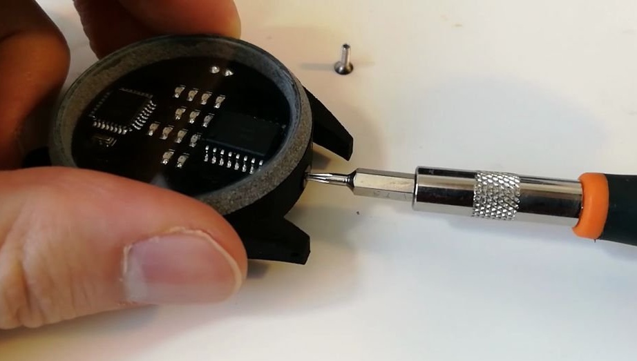
Insert the watch ring, aligning the screw holes and buttons.
Insert 6 mm M2 screws into the screw holes and tighten them. The screw heads are painted black.
Insert the clips into the eyes of the straps.
Install the watch straps.
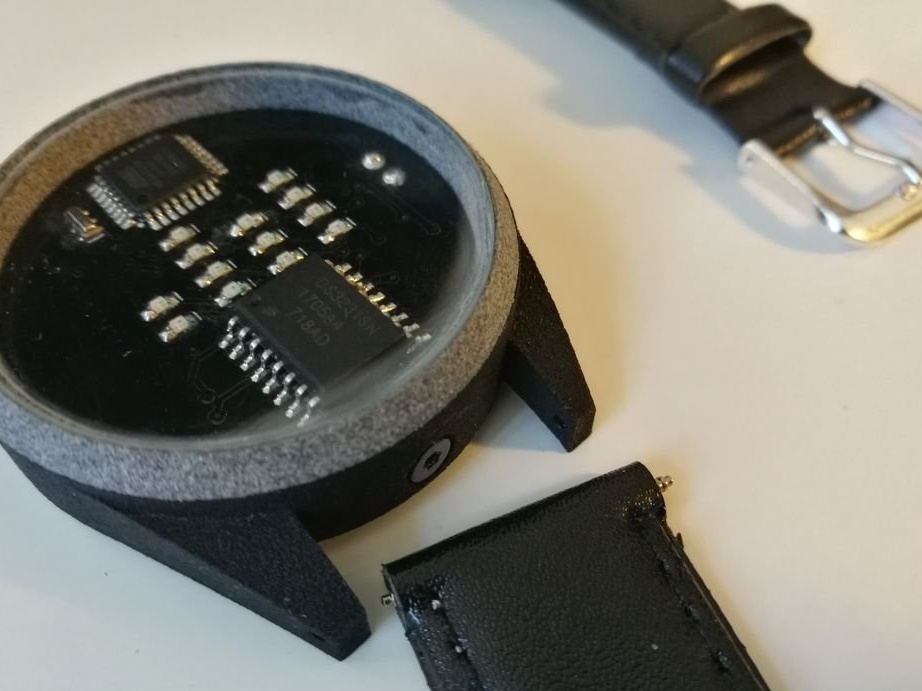

All is ready.
The whole process of making watches can be seen in the video.