

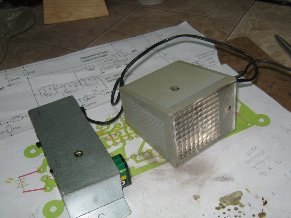
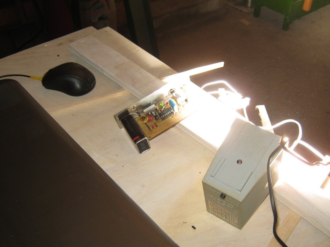
Light synchronizer - a device that allows you to use an external flash, with a camera that does not have sync contacts. The device catches the light pulse of the built-in flash and ignites the slave.
Many modern digital cameras, when working with the (built-in) flash, fire it twice at a certain interval - the first impulse is estimated to determine the exposure and white balance. Following with an interval of several tens or hundreds of microseconds follows the main, working impulse. An ordinary simple light synchronizer will launch slave flashes according to the first estimated pulse, and by the time the worker pulse is ignited, external flashes will go out for a long time. The photo will turn out even darker than if only using the built-in flash of the camera. So, you need a device that transmits the first light pulse and works on the second. Here, a simple device is described that implements this principle of operation and allows you to connect old network flash units with high voltage to sync contacts.
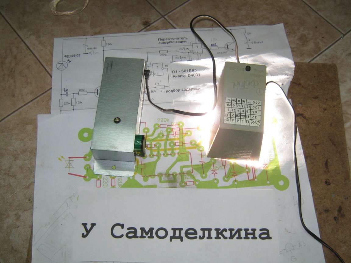
So. The light synchronizer is designed to work with the old domestic Photon flash network.
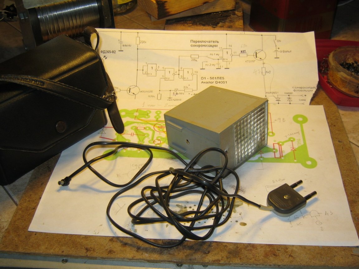
The scheme of the light synchronizer is as follows.
The circuit does not contain scarce parts, it is easy to assemble, and with proper installation it immediately starts working. You may only have to adjust the RC chain to a specific model the camera. The current consumption of the device is minimal - the battery of the type "crown" is enough for at least a year of operation. For example, an oxide capacitance charge of 47 μF (instead of C1) is enough for a dozen device operations.
A photo diode with a significant crystal area, high sensitivity, and a wide radiation pattern was used as a photosensor. These were used in the remote control of 3UST generation TVs. In this case, the device fires in any position with respect to the leading flash and at a considerable (within the premises) distance. You can try to use other factory and homemade photosensors, for example, the KT3102 transistor (in a metal case) with a remote cover and a diode switch.
The K561LE5 chip is interchangeable with an import analog of D4001. Instead of KD510 diodes, KD520, KD522 are suitable. It is desirable to use small-sized resistors - a change in their ratings within 20% will not affect the performance of the circuit.
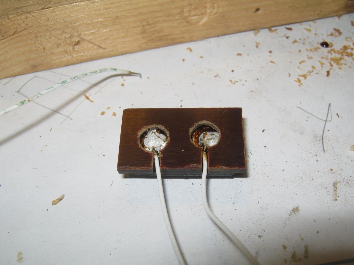
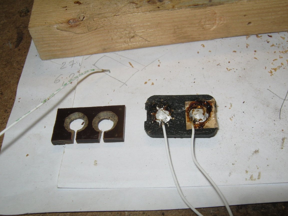
The hardest thing to find is a standard flash socket for sync contacts.It uses the slot from the Photon flash kit - its plastic case was equipped with a removable plastic shoe for attaching the flash to the camera. There was a socket at the bottom of the shoe.
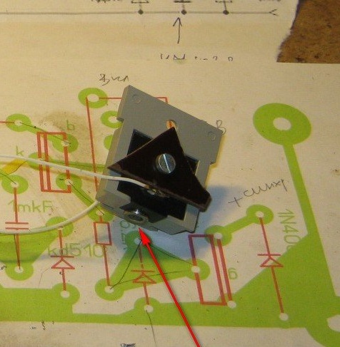
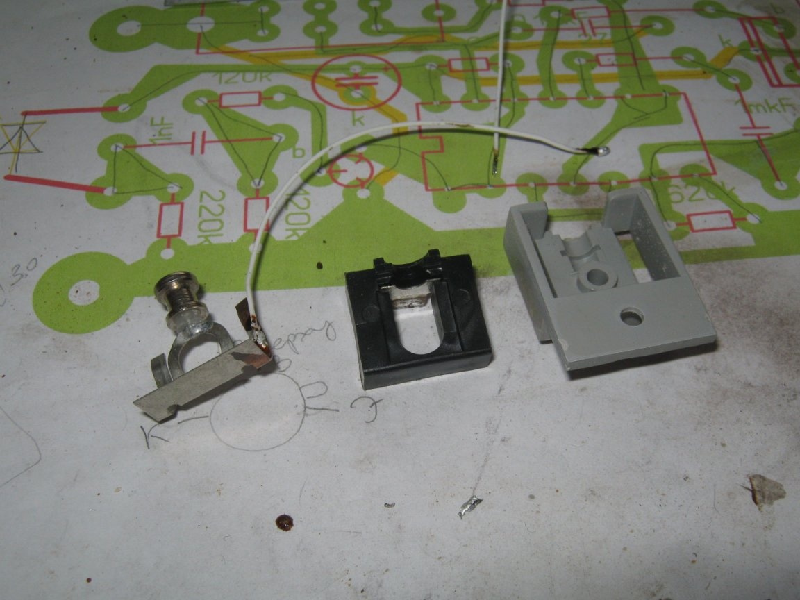
You can try to contact the camera repair shop or remove from the old broken photo equipment. In fact, if you intend to work with only one constant flash, the connector can be replaced with something more common, for example, a pair of DB9 or something more miniature. It should be borne in mind that on flashes like Photon, the power is transformerless and sync contact high voltage. Here you should use a socket with recessed contacts, excluding accidental contact. An option when working with one permanent flash is to place the synchronizer in its body (in a new compartment made outside).
What was required for the manufacture of the device
A set of tools and materials for the manufacture of printed circuit boards. A set of tools and instruments for radio installation. A set of small bench tools and a powerful soldering iron for the manufacture of a metal case.
So let's get started
The printed circuit board of the device was developed in the specialized Sprint Layout program and made using film photoresist.
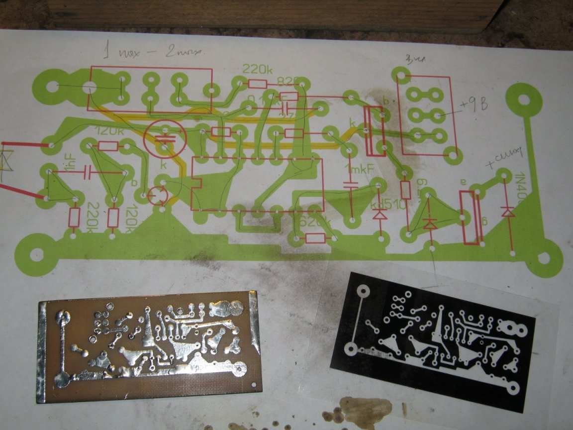
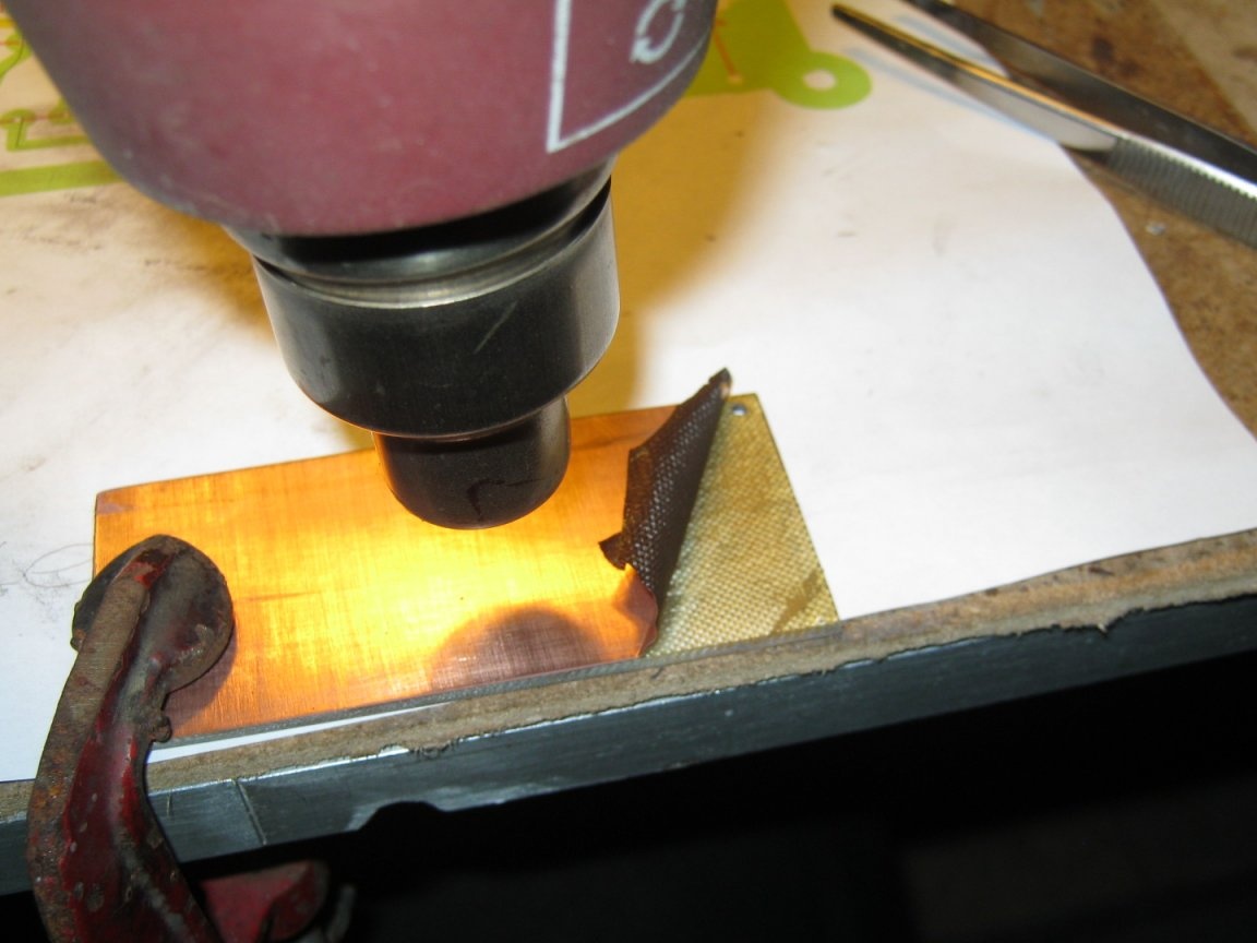
Billet foil material had to be used as a blank, although the printed wiring was not involved on the part side. There was no other material at hand. In high-frequency devices, it makes sense in such cases to use this layer of foil as a screen, countersink the holes on the part side of the installation. Here, the extra layer of foil will only interfere - during the etching of the board, covered up the unnecessary layer with adhesive tape so as not to waste the etching solution, and after that, removed it with tweezers, pre-heating it with a building hairdryer until the glue softens.
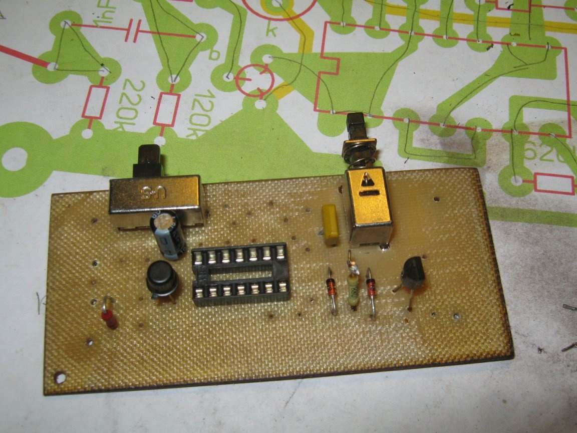
After a full cycle of work on the manufacture of the circuit board, he set about assembling the elements. First, the most unpleasant ones are large switches and a socket for a microcircuit. The switches were taken from an old board of a portable imported radio, they had to drill a few standard holes for them. The findings of the microcircuit socket are not particularly good and are sensitive to overheating.
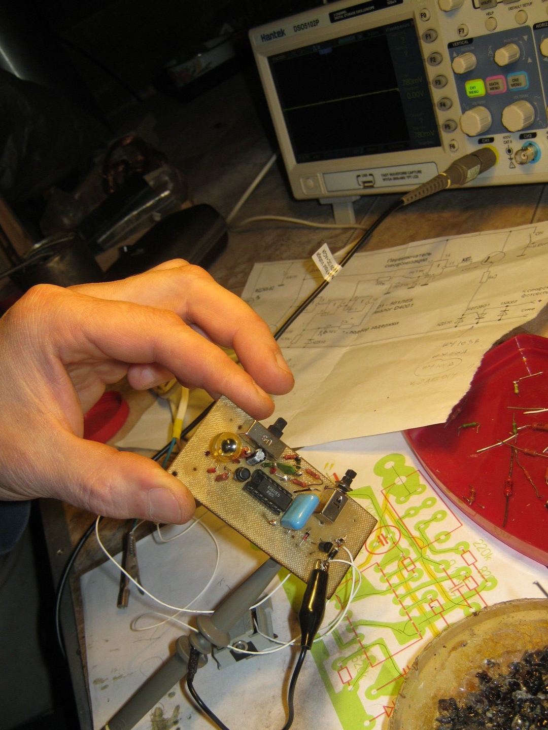
After installing all the elements, I checked the installation, connected the sync contact socket and installed a microcircuit in the socket. Powered the device from a stationary power supply.
Puffing the flash of the camera toward the switched on device, I traced the appearance of the pulse at the beginning of the circuit and its passage through various elements with an oscilloscope. I had to pick up (reduce) the resistor in the KT315 base circuit until the transistor opens reliably.
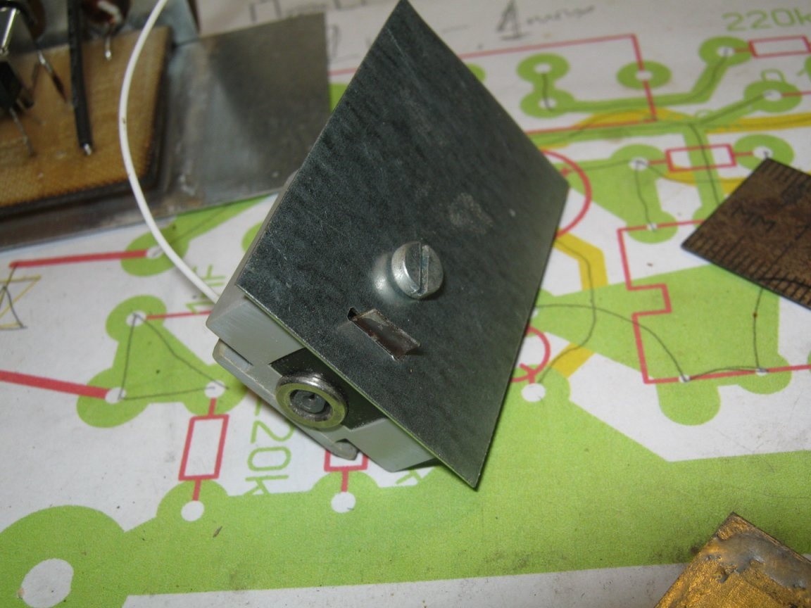
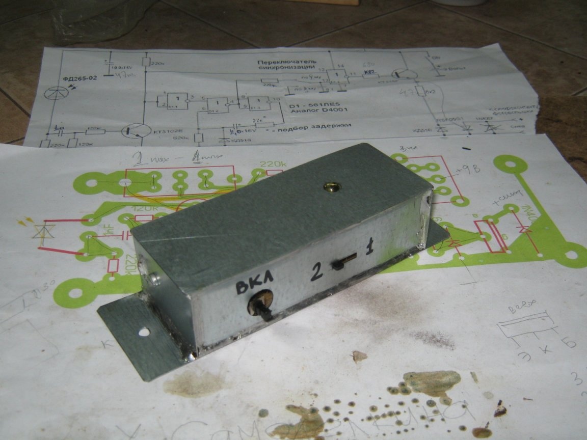
Having achieved the operability of the circuit, he took up the manufacture of the device body. I decided to make it out of tin. At the same time, each side of the case, each of its panels can be adjusted to the elements of the device separately and mounted separately from the outside, which seemed convenient.
The first thing I did and mounted the panel on the part of the controls is the power switch button and the delay switch. On the same panel, a pad for connecting a 9 V battery will also be installed inside. About the battery it is worth saying a few words.
In the economy of the author there are a number of devices with battery power 9 V, the need for which arises only periodically. Keeping inexpensive batteries in such devices all the time is dangerous. It turned out to be quite convenient to have a stock of several such batteries and insert them into the desired device if you need to work with it. With this approach, it would be convenient to have devices with quick access to batteries (at least stationary devices), without having to open the battery compartment. It was decided to try out this kind of battery installation.This should be a certain opening in the case a little larger section of the battery. A standard block is fixedly installed at the bottom of the compartment. The battery should protrude about a quarter from the compartment so that it can be caught with your fingers.
The standard block (from a failed battery) was equipped with a special insulator from a piece of PCB. At the installation site, a bracket is cut out, bent and soldered to secure the pads. Using short protruding staple petals, the complete assembly riveted to the duty station.
I shortened the wires from the block in place and connected it to the necessary points of the circuit, checked the performance.
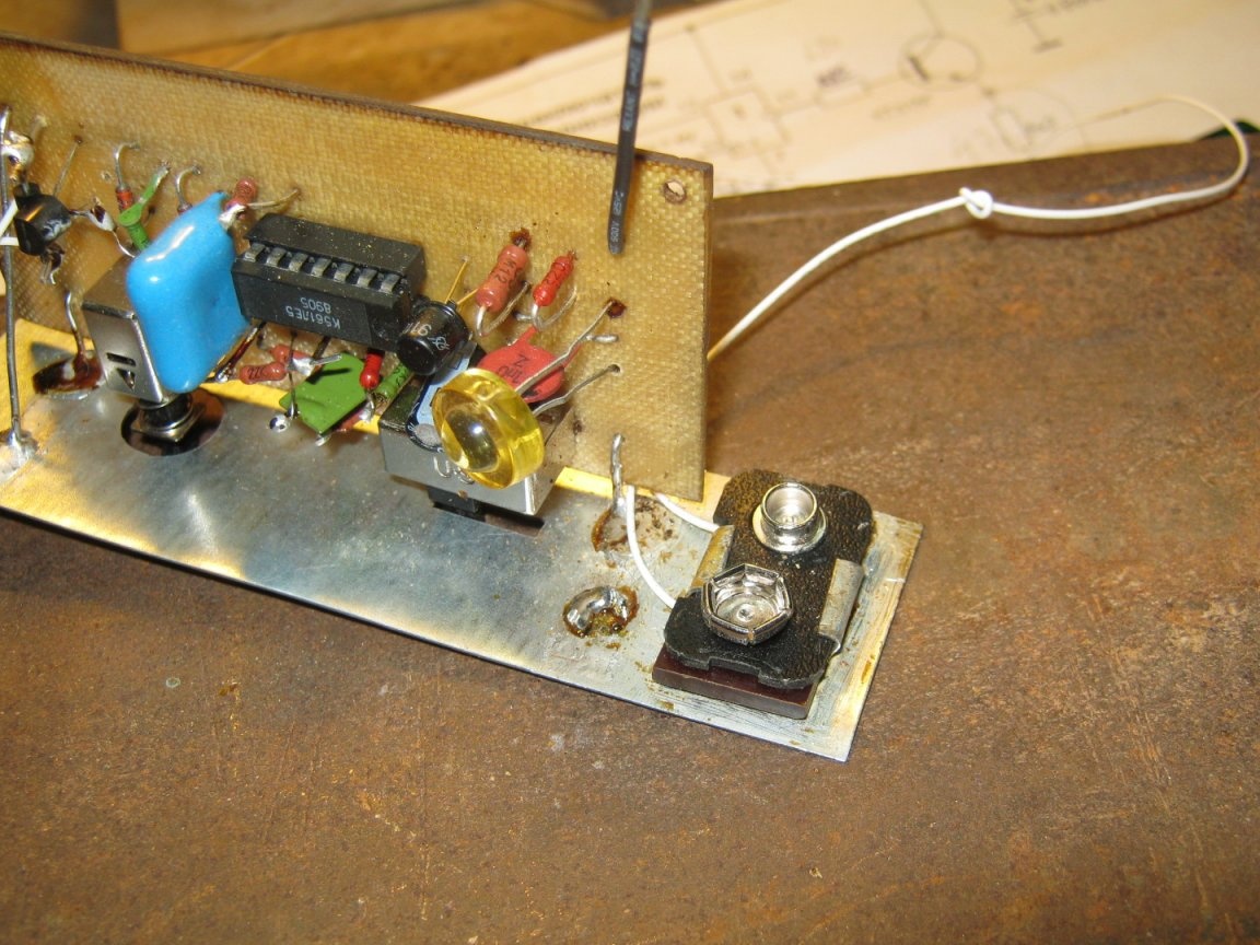
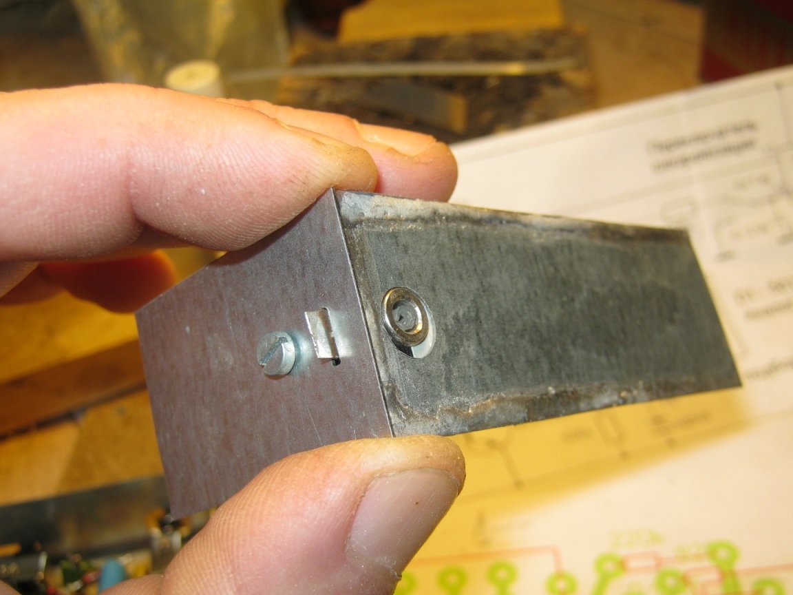
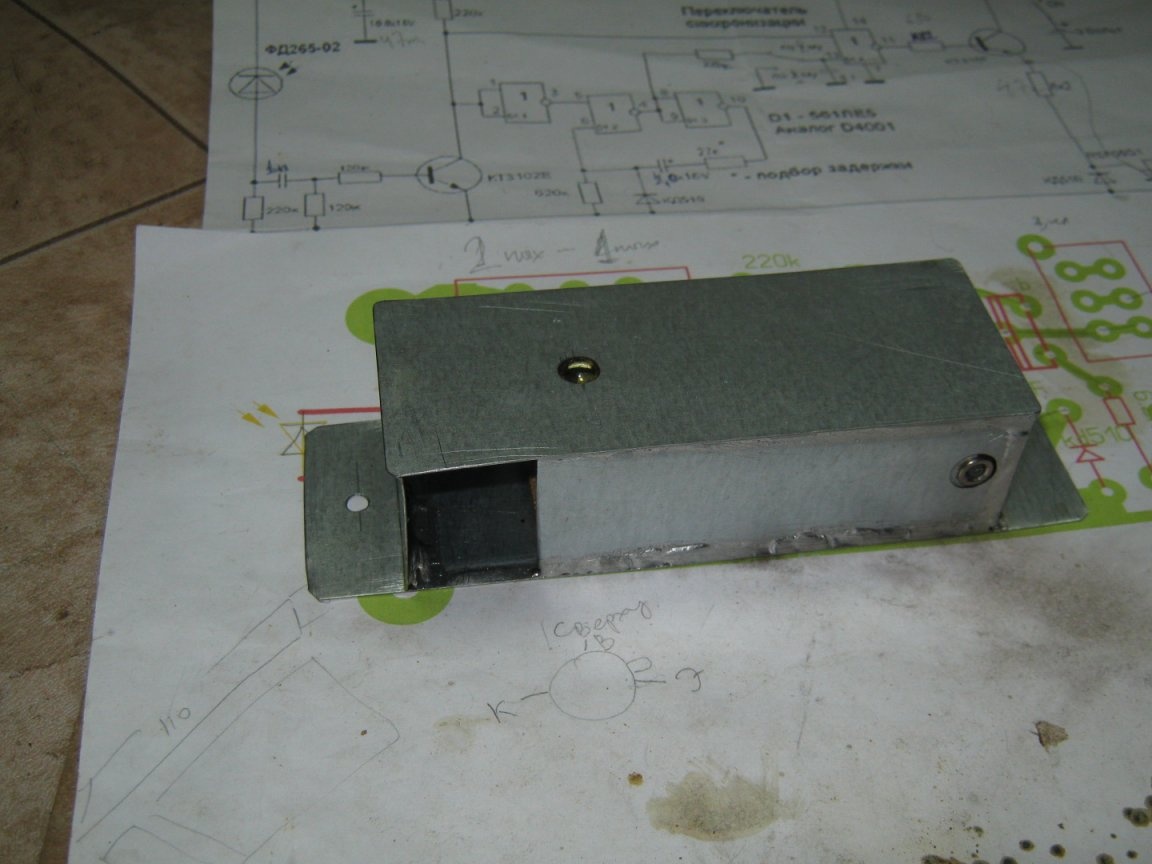
The next time-consuming part of the design was a connector for sync contacts. The shoe from the flash kit was installed inside the case, in its corner. For one of its petals (-) had to make a gap in the end wall of the housing, the hole for the outlet - in the side. He acted like this - he marked the end wall and sawed a rectangular opening for the petal and a hole for the screw with a jigsaw, tried on a shoe.
Now you can mark the adjacent wall. I cut a hole for the outlet.
He began to assemble the hull. Cut and prepared (the edges are cleaned, tinned with zinc chloride, washed with water), the body parts were assembled on a live thread. I cut out the bottom plate-bottom of the case with a margin of length. 20mm on each side. These will be ears for fastening with screws on a future wooden stand for flash. When everything came together, he turned on a powerful soldering iron and carefully soldered the seams, more for beauty - the case is still not sealed and it is also not required to have special strength.
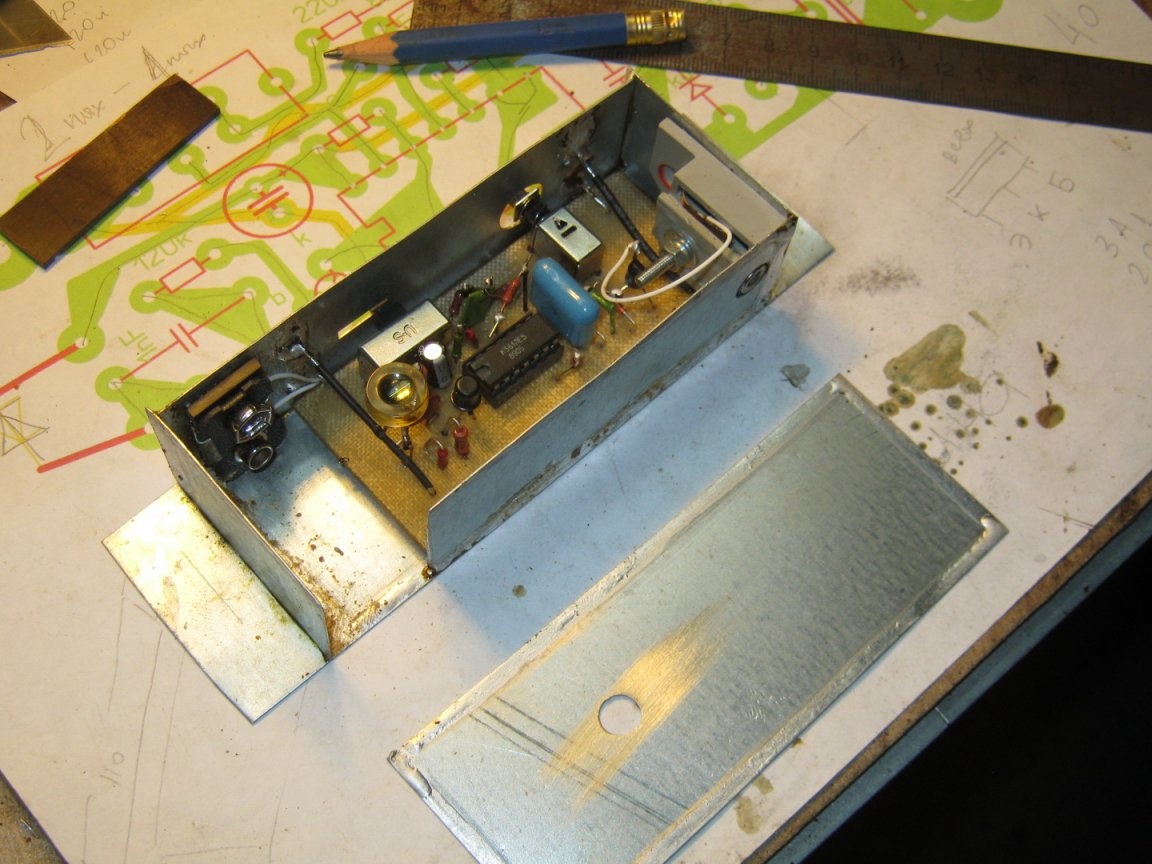
I prepared the blank for the top cover similarly to other pieces of iron. I extended the legs of the photodiode, set it up with two tinned wires, so that only a plastic lens protruded from the body. Marked her place on the lid, cut it out with a jewelry jigsaw. After the last performance check, the lid was soldered into place. He removed the flux residues, dulled the sharp edges of the glands with a fine sandpaper, wiped the case with a cloth moistened with TsAPON varnish, preventing droplets from flowing into the switches and the sync terminal socket. Lacquer industrial marker signed governing bodies.
Babay Mazay, January 2020