


Recently brought in-law, the father of some of my grandchildren, in garage a rather beaten children's electric car (hereinafter referred to as the machine), so that the youngest traffic rules would be mastered. He’s a man of arms, started up mechanics and an electrician, that's why he turned to me - when starting off, there is a sharp jerk, the little one’s head twitches. He knew that a few years ago I installed soft starters in cars, which were rented out in the parks on weekends (and not only near every major store), the kids went for a drive, and smacked me. Well, the best practices remained, why not.
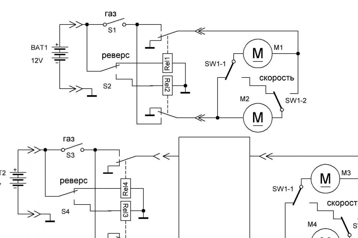
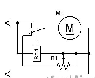
A machine of this class has:
- "gas", pedal, switch without a hint of regulation;
- “box”, the switch is fast-slow, turns on both engines either in parallel (fast) or sequentially (slowly);
- "reverse", switches the polarity of the voltage supplied to the motors. And that’s all. Even bluetooth-controlled cars have the same block diagram. There are options for using a relay for PWM, but as one movie says: "This is not serious!" So, a very simplified scheme looks like this. Nearby is the inclusion of our module.
What is the filling of our module? This is a power transistor switch (it is too complicated with a direct current thyristor) controlled by a PWM generator, plus a time relay (RV), which, after accelerating (5 ... 10 seconds after starting), contacts the power relay with a short-circuit switch to reduce losses and unloading the key.
The principle of operation of the PWM generator is explained in this diagram.
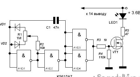
The frequency chain consists of C1 and R1, and the ratio is log. 1 and 0 - duty cycle - from the position of the slider R1, more precisely, from the ratio of the resistances of the upper and lower parts of the resistor. These parts control the speed of the charge or discharge of the capacitor, depending on the diode. When they are equal, the duration of the glow and "non-glow" of the LED will be equal. In one of the extreme positions of the slider there will be a long glow with a short extinction time, in the other - short flashes.

But the diagram shown works well with manual adjustment, for our goal - soft start - it is better to use the NE555 timer (hereinafter simply a timer), "sharpened" specifically for such modes. Domestic analogue of KR1006VI1, other analogs: There is no sense in giving a full description, there are reference books, but the point is that it has an “Control” input (CTRL), 5 microchip leg. Here is a description from Radiokota:
…
I’ll add from myself that if the voltage on the 5th leg is equal to or greater than the supply voltage, the generation breaks down, at the output one, the key is fully open (which is what we need).
Let's consider real schemes.
The very first serial circuit designed and manufactured on bipolar transistors. (The word "serial" means that I made more than 10 pieces of them).
Features of this circuit:
- a bunch of powerful transistors (KT819, then KT863) - bad, take up a lot of space, heating;
- a bunch of alignment resistors - very bad, take up space, strong heating;
- a time relay on a thyristor - a large capacitor takes up space;
- headphone, sound overclocking simulator - good, but takes up space.
Further, the main production scheme. We will consider this in more detail.
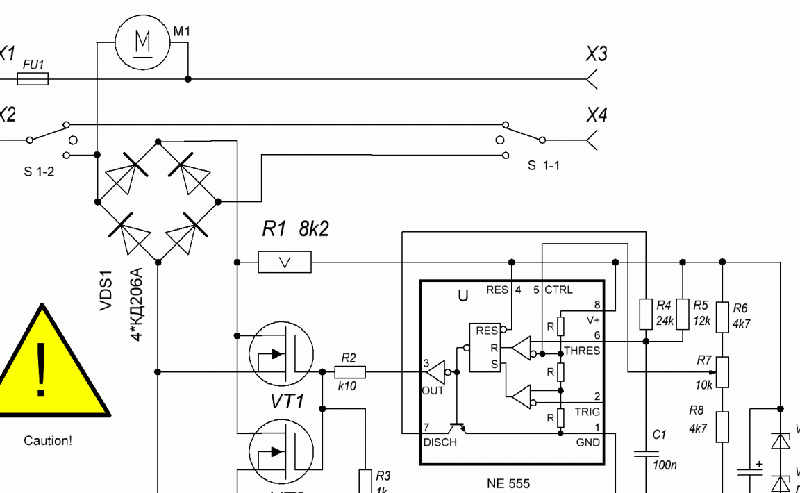
Provides smooth starting, reverse gear is jerked. To save money, the customer agreed. The sound simulator was abandoned. Field-effect transistors 55N06, discharged from China, were rejected by 20%, but the remaining ones worked so well (small losses and heating) that they did not immediately turn on the PB, but refused (parts K1, VD4, VT2, C5 and R5 were not installed). The acceleration rate is determined by the capacitor C3 (from 1000.0 to 4700.0 μF) and the resistor R1, the nominal value is selected experimentally. It is not difficult to obtain a restriction or the ability to adjust the speed; you need to connect in parallel C3 a variable or tuning resistor with a value of about 10 ... 20 kOhm, the slider of which is connected to the 5th foot of the timer.
When moving backward, the plus and minus change places, the power 555 is cut off by the VD2 diode. The motor current passes through a diode built into the fieldwork VT1, in which the permissible current is the same as that of the main structure. The resistor R8 connected in series with the VD3 damping diode has little effect on its damping properties, but protects it from overload during reverse. The timer here is turned on according to an atypical scheme, there are fewer details, the functions are the same. The power to the timer is supplied through the resistor R3, not only to improve power filtering, but mainly to create an excess of voltage on the 5th leg over the voltage of the timer to “plug” it in the desired position. Its value when using analogs of the timer can vary greatly due to different current consumption. Resistor R6 and diodes VD2 and VD4 - for discharging time-setting capacitors C3 and C5 when the power is turned off. To eliminate the pause at the start of starting, between the minus C3 and the minus the power supply, a trimming resistor of the order of 1 kΩ not indicated in the diagram can be installed, the setting is individual. Used in the described product. The generation frequency is determined by C2 and R2, at these values of approximately 300 ... 500 Hz, the sound simulator gives a decent simulation of acceleration. For smoother acceleration, C3 can be increased to 4700.0 uF.
And a circuit with soft start in both directions. Key Features:
- two transistor switches 55N06;
- inclusion of the timer through the diode bridge, at any connection the power comes to it in the correct polarity;
- because the voltage drop on the built-in diode of the idle fieldman is noticeable, it is necessary to use a PB, also connected through the bridge and having two groups of closing contacts;
- damper - capacitor instead of a diode.
You can apply voltage in any polarity - the engine will smoothly accelerate in the right direction.
According to this scheme, we will assemble our product.
A little bit about the supply voltage. I had to deal with 6, 12, 18 and 24 volt systems. 6B - low-power obsolete, it was necessary to put scarce 5-volt relays. 12-volt typical, for 18 and 24 V, you need to set the zener diode on the timer (as in the very first circuit, or a type 7812 chip). At 24 volts, the fastest, sometimes with a large roll-over, an accelerated stop requires a brake, this is not difficult.
When the power is turned off, the relay shorts the motor (dynamic braking) through a wire trimming resistor R1 with a value of several tens of Ohms, which selects the braking intensity.
We pass to manufacturing.
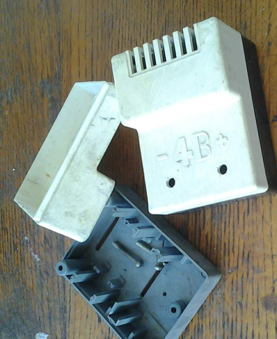
There is a body. A little refinement on breaking out unnecessary entrails.

PCB blanks are preserved, no need to poison.
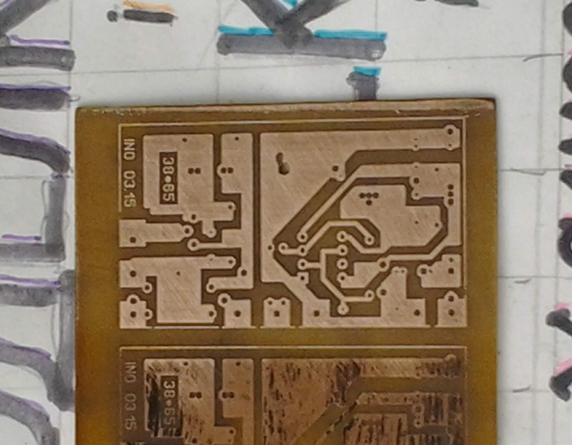
We clean, grind.
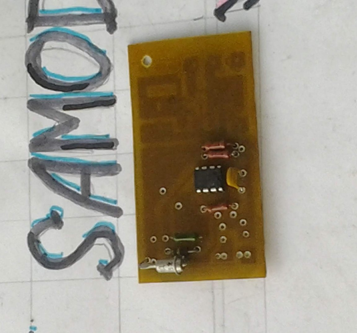
We start stuffing the board with the details.
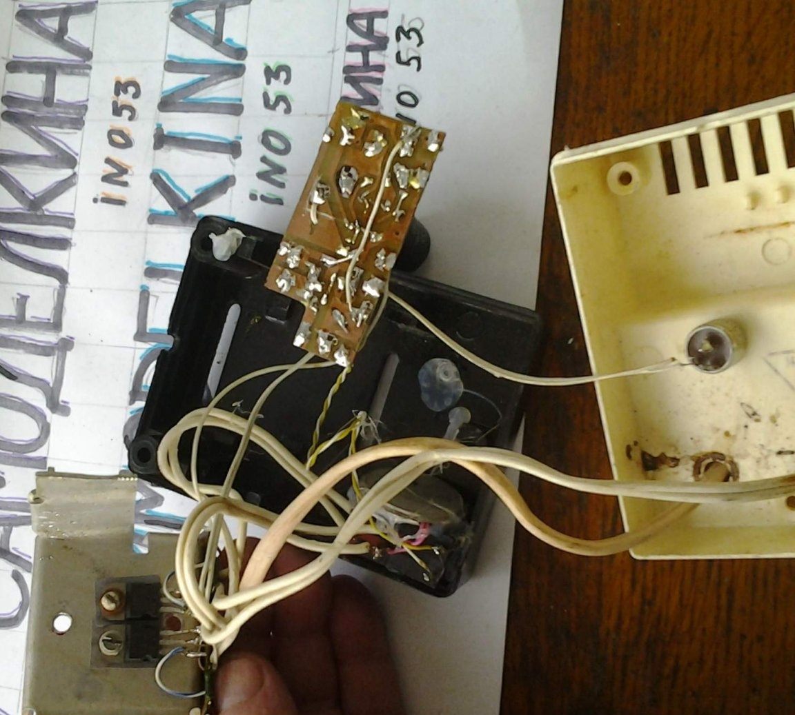
And then shove it into the case.
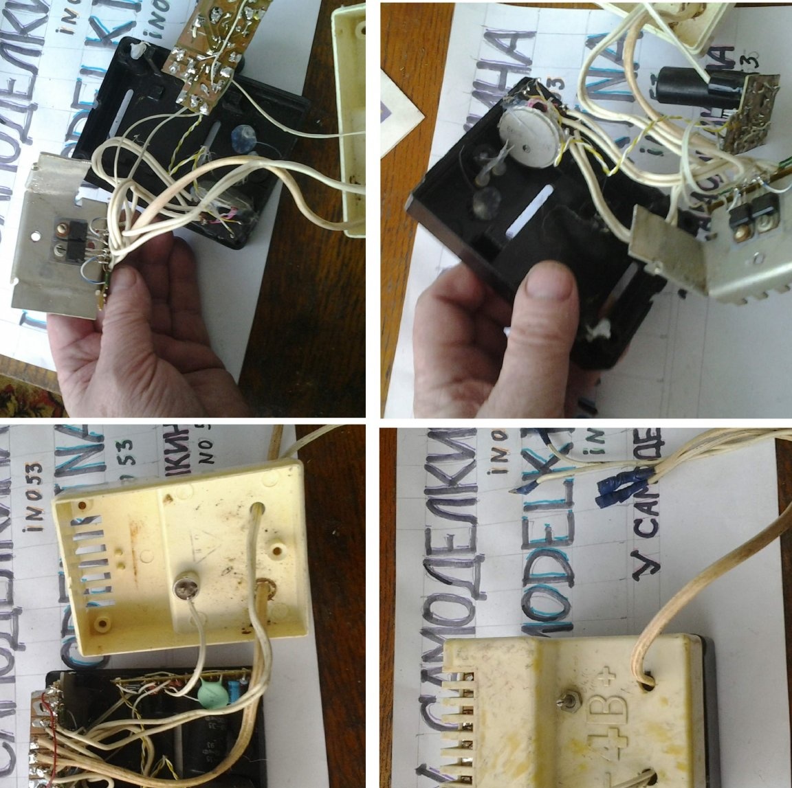
Naturally, not everything went right away, but with the help you yourself know what the product is still assembled.
Now shoot the video and insert it.
Starts of engines are shown directly and through our product, only 50 sec.
And more about the options for these schemes. If it is interesting, we will discuss.
Powerful circuit, 1.5 kW at 48 V (incomplete circuit).
High voltage regulator, there is a tricky function.
Wire feed regulator in welding PA.
That's all, comment.