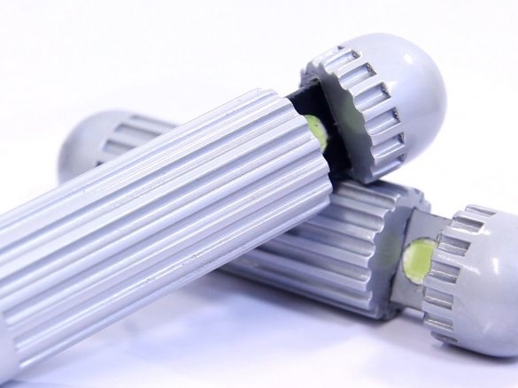
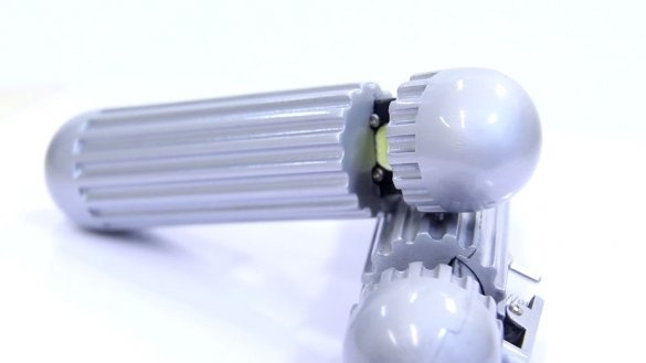
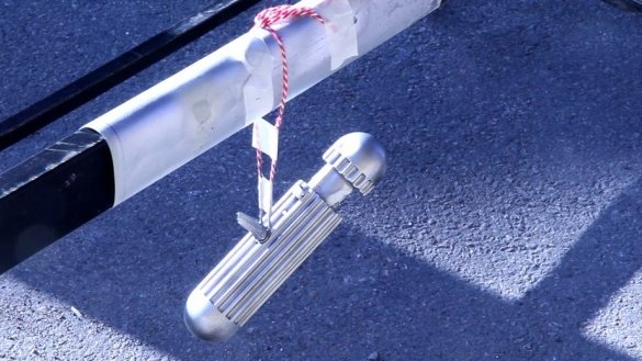
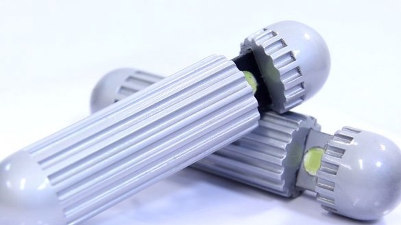
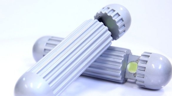
Black suit, white shirt, black sunglasses, memory eraser and you are ready to save the world.
This memory eraser was made for going to a costume party. To assemble the electronics, the master provided several circuits. Using some of them, you can use devices like a flashlight.
Tools and materials:
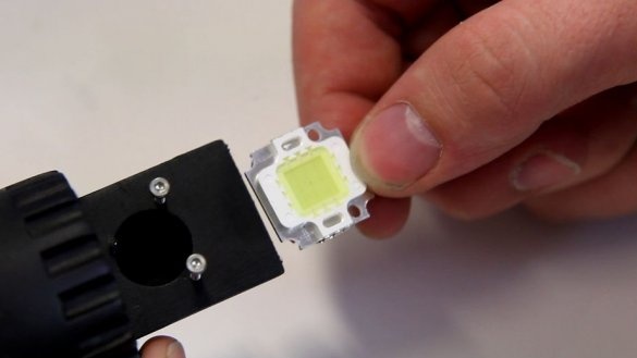
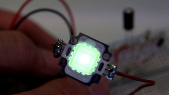
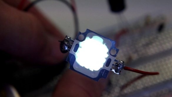
-LED 10 W (12 V);
- Electrolytic capacitor 330 uF;
-Tumbler;
Diode 1N4007;
- 9V battery;
-Connector for battery;
-Two resistors;
-Two fountain pens;
-Clip;
-3D printer;
- Thermogun;
-Sandpaper;
-Drilling machine;
-Aerosol paint;
-Putty;
-Black primer;
Step One: 3D Printing
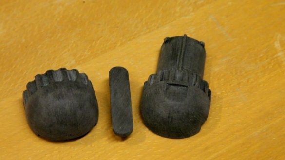
The case is printed on a 3D printer. Files for printing can be downloaded below.
Simplified Neuralizer - Men in Black
Step Two: Grinding
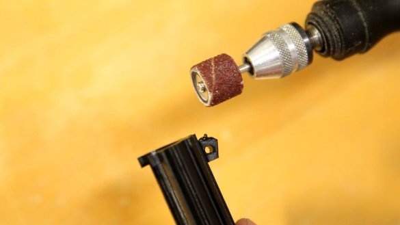
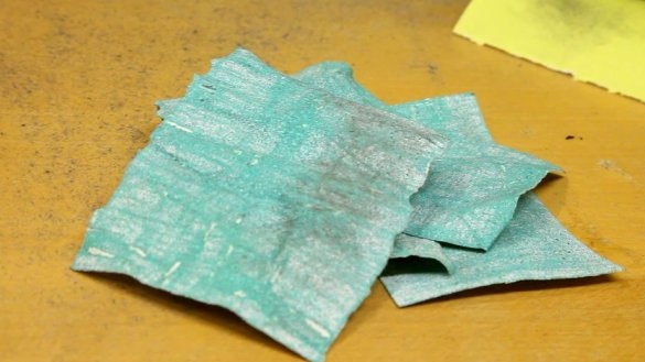
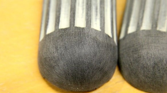
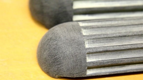
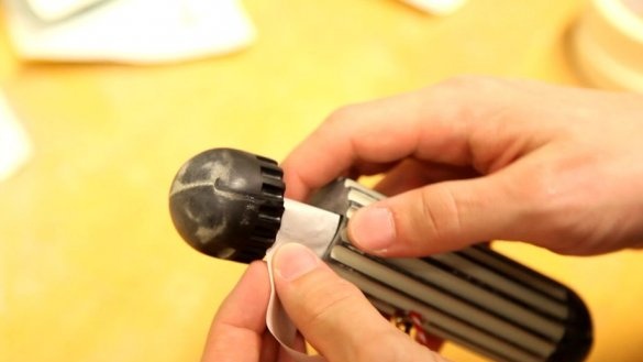
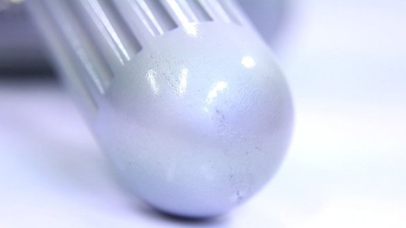
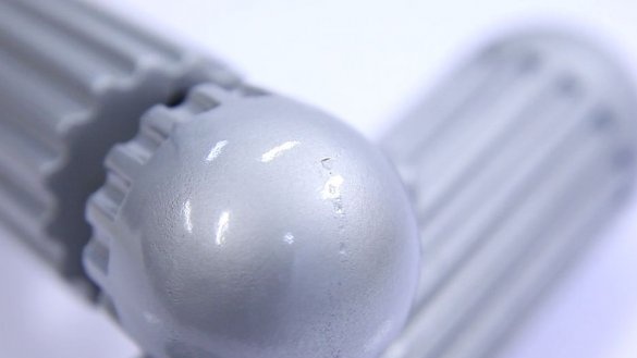
Printed parts are sanded. Grounded. And polished again. It is necessary to give them a smooth look.
Step Three: Build the Top
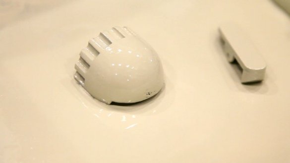
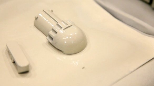
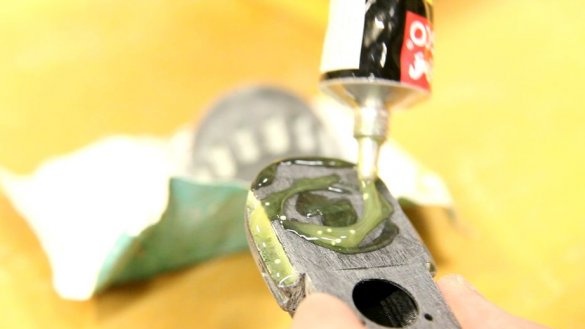
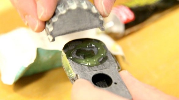
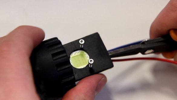
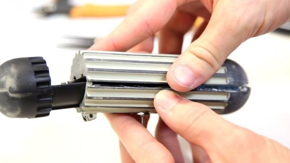
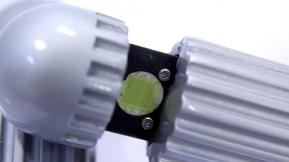
The upper part consists of two parts. The master applies glue and glues parts. Subsequently, an LED will be installed in the hole.
Step Four: Schemes
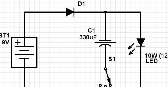
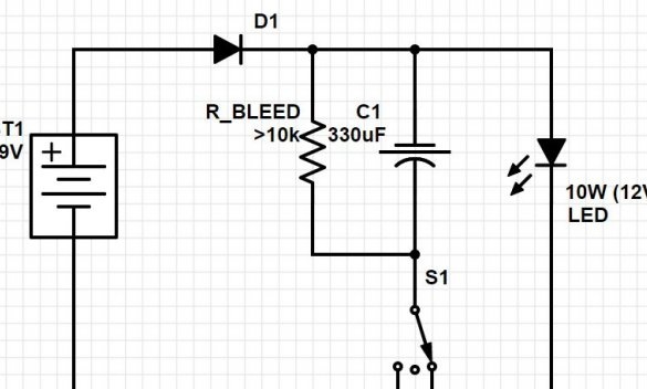
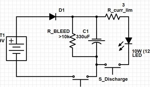
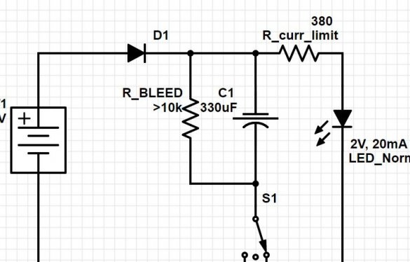
As already mentioned, the master provided four schemes. You can collect on any of them.
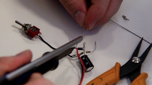
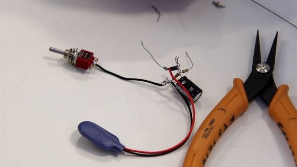
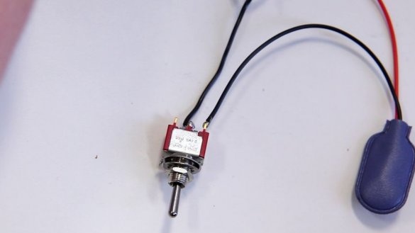
The simplest circuit has a three-position switch. In the middle position, everything is turned off, the capacitor is charging to the left, and the capacitor is discharging to the right. The resistor is not installed, since the LED is 12 V, and the power is from a 9V battery.
In the following diagram, a discharge resistor is installed, which will ensure that the capacitor does not remain charged for long periods of time, equalizing the potential accumulated on the capacitor.
In the third scheme, the flashlight function is implemented. A 3 ohm current limiting resistor and two switches are installed in the circuit. When both are locked, the device works like a flashlight.
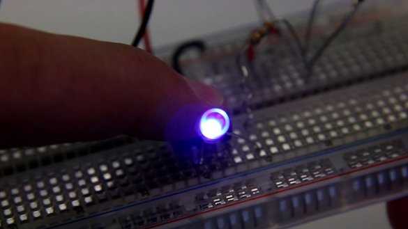
The following is an option in which a LED with a nominal value of 2 V and a voltage of 20 mA is used.
Step Five: Assembling the Circuit
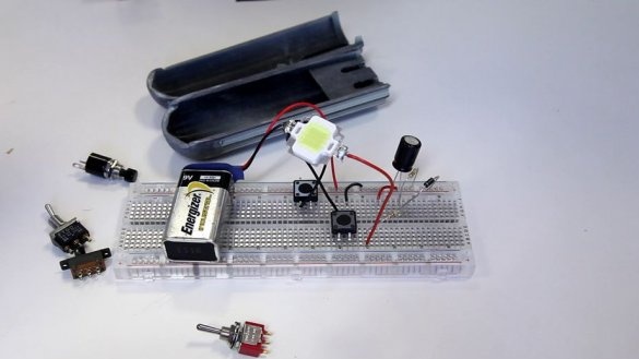
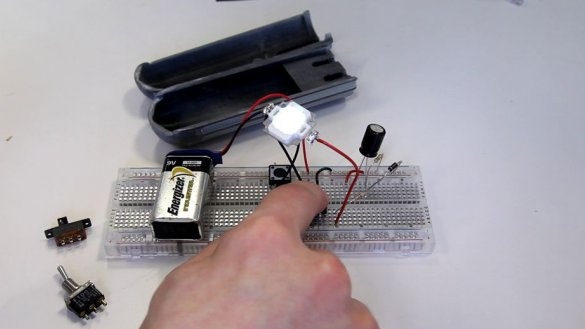
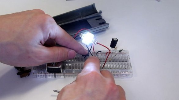
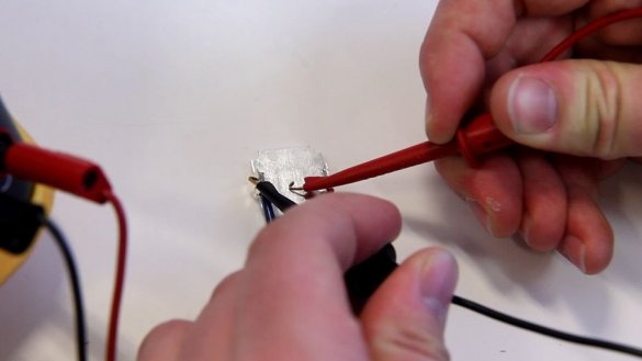
First, the wizard checks the operation of the circuits on the breadboard.
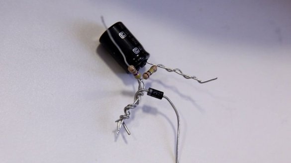
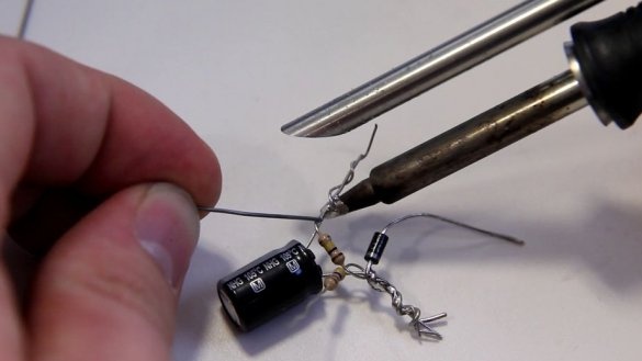
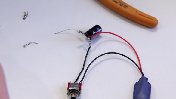
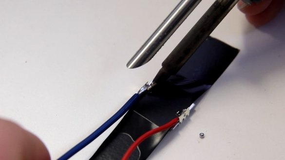
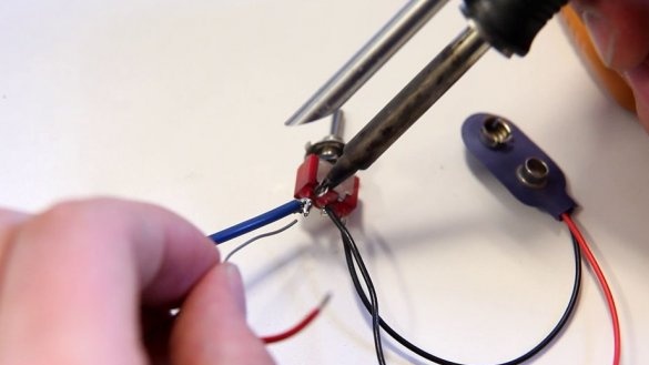
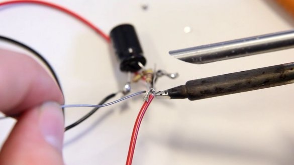
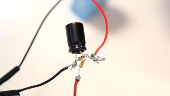
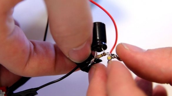
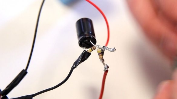
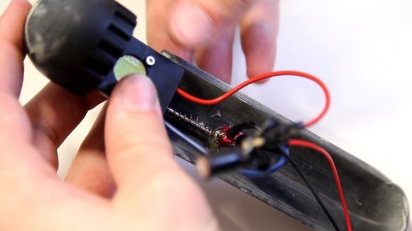
Everything works, and the master assembles the circuit with a mounted installation.The master decided to install a discharge resistor and a current limiting resistor. The LED, capacitor and diode are all polarized - meaning that they must be soldered “in the right way” to work. For the diode and capacitor, a white line on the chassis indicates ground. Another capacitor has a long leg connected with a plus.
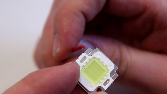
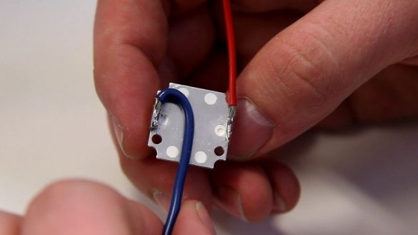
Sets the LED. The LED is labeled + and -. If conventional LEDs are used, then the polarity can be determined by the length of the legs. Long leg + (anode), short - (cathode).
Continues assembly.
Step Six: Mechanical
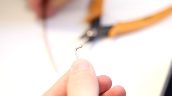
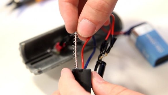
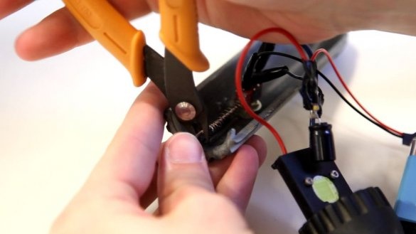
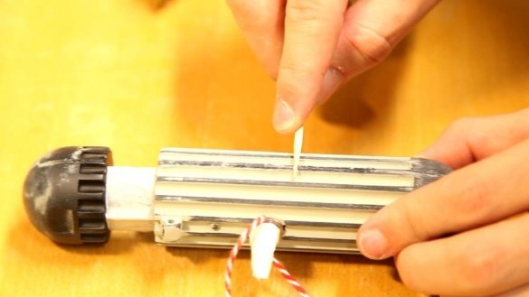
To make the lid open when the latch is pressed, the master took the spring from the old handle and used a thick clip as a lever.
Seventh step: assembly
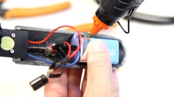
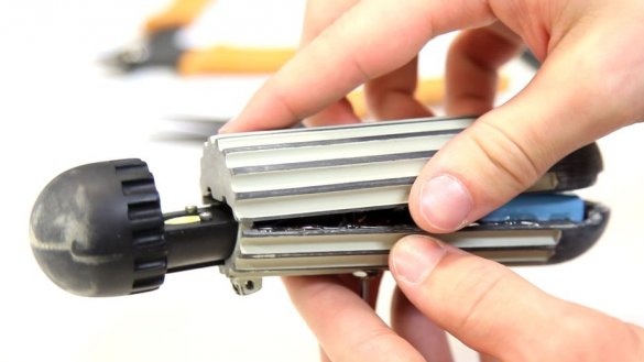
Before assembly, it is necessary to once again check the operability of the circuit and the mechanism. Connect and secure the battery, assemble the housing.
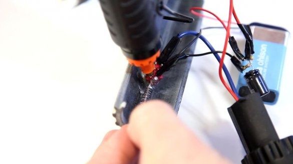
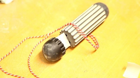
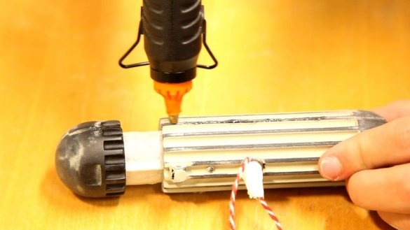
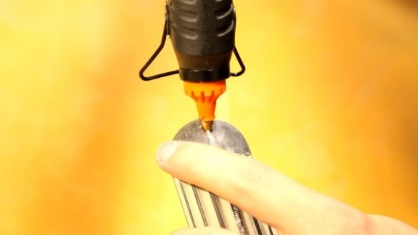
Fastens the rope. The joints are filled with hot-melt adhesive.
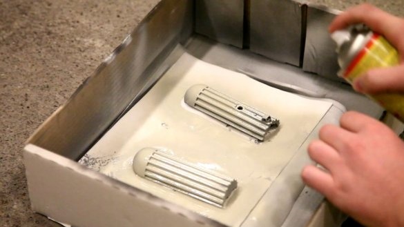
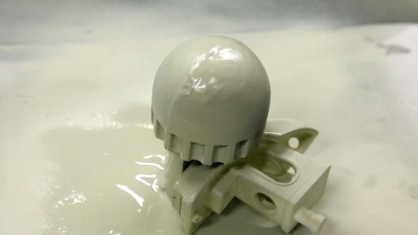
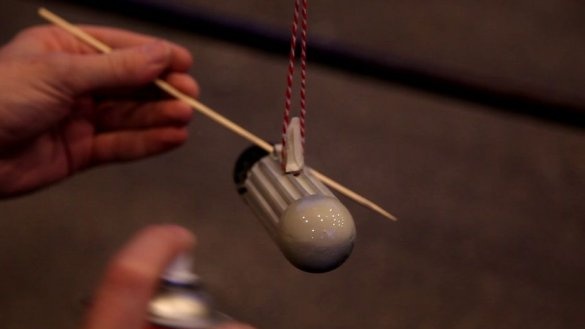
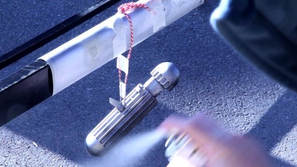
Step Eight: Painting
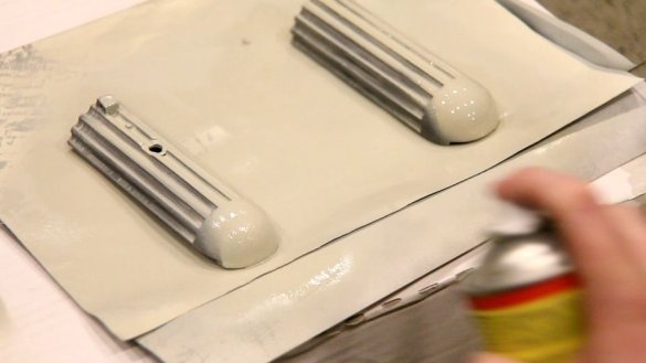
Hangs the device on a rope. Stains.
All is ready.
The whole process of manufacturing a "memory eraser" can be seen in the video.

