LED lamps and fixtures firmly won first place in the lighting of our home. But very often we are faced with the fact that the reliability of these devices does not meet our requirements. Analyzing dozens of failed lamps, studying their design features, as well as getting acquainted with the used elemental base, I established the reasons why they burn out. For example, very often the lamp driver is located on a panel with LEDs and when it is heated it fails. In other cases, when the driver is located closer to the base, it burns out from a sharp change in the mains voltage. LED burnout occurs only when the driver is no longer able to cope with its task. Therefore, when developing the system, I decided to completely abandon the use of the driver. In addition, I had to change the parameters of the voltage supplied to the lamp.
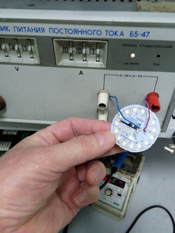
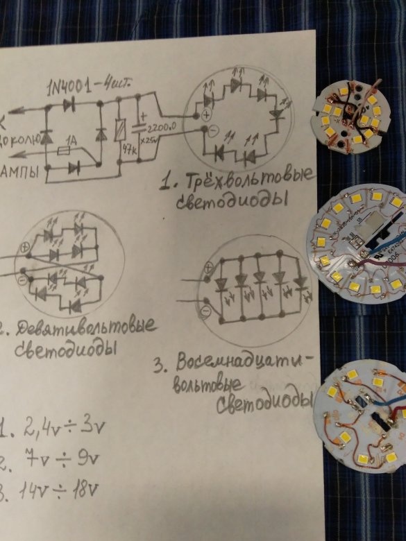
And ultimately - to expand the operational capabilities of lamps and luminaires i.e. make them adjustable. I invite everyone to familiarize themselves with my project. The theme of the first stage is the modernization of lamps and fixtures. All lamps and luminaires supplied to our country have different connection schemes for LEDs and, moreover, their parameters are not the same. And this, in my opinion, is not a very difficult question, and we will figure it out. In a practical study, namely: applying a constant voltage to a single LED, the following results were obtained. At a voltage of 2.4 V - a weak glow, at a voltage of 3 V - a bright glow. So the diodes used in this lamp are designed for a nominal voltage of 3V. On the second socket from another lamp. At a voltage of 7V - a weak glow, 9 volts - a bright glow. So the diodes used in this lamp are designed for a nominal value of 9V. On the third panel from the third lamp, 14V - a weak glow, 18V - a bright glow. So the nominal value is 18 volts. There were also such ones, 28V - a weak glow and 36V - bright, but I do not use these panels.
I decided to use the first, second and third version of the panels with LEDs, which can be connected to a circuit with a rating of 18V - we will take it as a standard. Therefore, after opening the lamps, it is necessary to determine what rated voltage their LEDs are. And by soldering, make the connection as in the figure.
The photo shows samples of redone panels from various lamps.By scraping the upper layer of paint on the panel with a scalpel and carefully cutting off the conductors of the printed circuit board, to the insulating layer, the connection option necessary for the lamp is soldered. The soldered panels are varnished in places of cut and soldering. Next, we check for operability by connecting to the source.
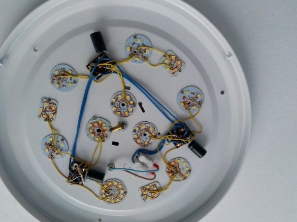
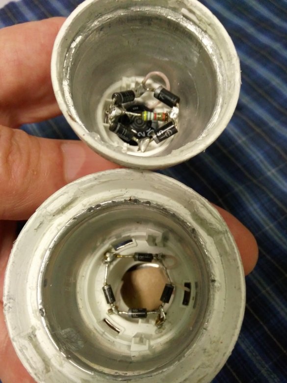
Now we collect the bridge circuit of the rectifier, soldering it into the lamp housing. We derive the ends from the cap through the fuse 1A. We insert an electrolytic capacitor 2200mkf / 25v into the base, unsolder the circuit and assemble the lamp. I really liked the option of upgrading the lamp purchased recently. I mounted panels from various lamps into it, and its body became like a heat sink.
Photo mount diode bridge. It is desirable to further isolate the electrolytic capacitor.
Modernized, according to the described method, lamps and luminaires should preferably be checked after assembly. Apply a voltage of 19 volts to the base, measure the current and mark with a marker. Many will have a question why I do not use the sold lamps on 12v or 24v. The fact is that drivers are also installed in these lamps and various types of LEDs are used.


