

On the Internet, there are many options for manufacturing similar circuits assembled using different combinations of transistors and the same principle of operation.
The main ideas were:
1. Assemble this device from the various after disassembling electronic rubbish details.
2. Make a finished design, ie including housing.
3. When manufacturing, save yourself from searching or self-winding the inductors indicated in the found value schemes, and use those that were at hand!
4. Conduct comparative testing of the design with factory-made equipment.
In this design used:
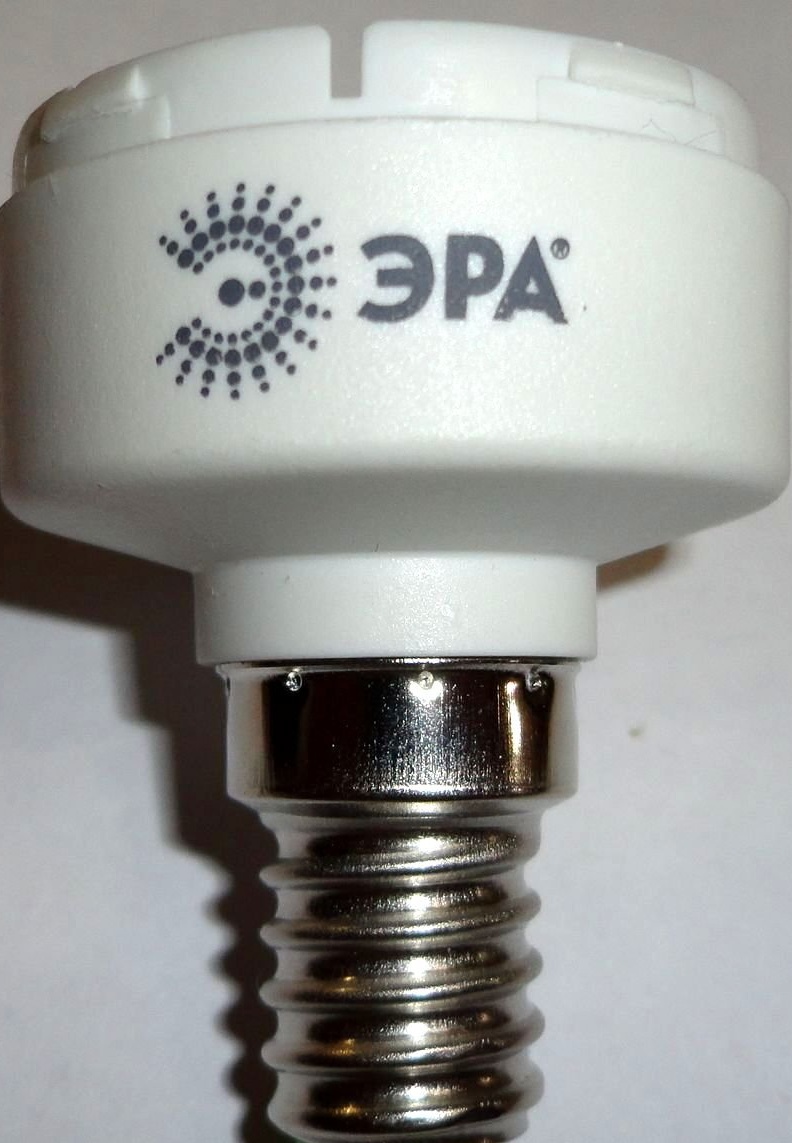
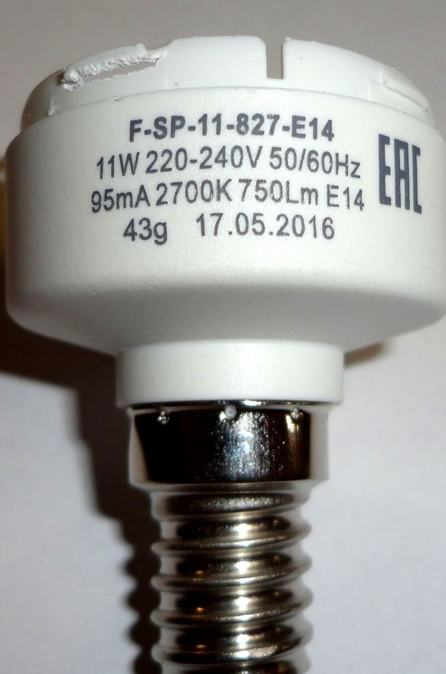
- Fluorescent lamps "ERA".
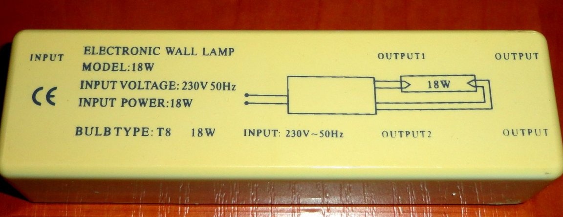
- Housing from a burned-out ballast from a fluorescent lamp.
- Foiled fiberglass single-sided 109x28mm.
- 3mm screws.
- Pieces of plastic.
- Radio parts according to the scheme.
Of the tools used:
- MFI type "Dremel".
- Soldering iron.
- Super glue.
- Screwdriver, wire cutters, etc.
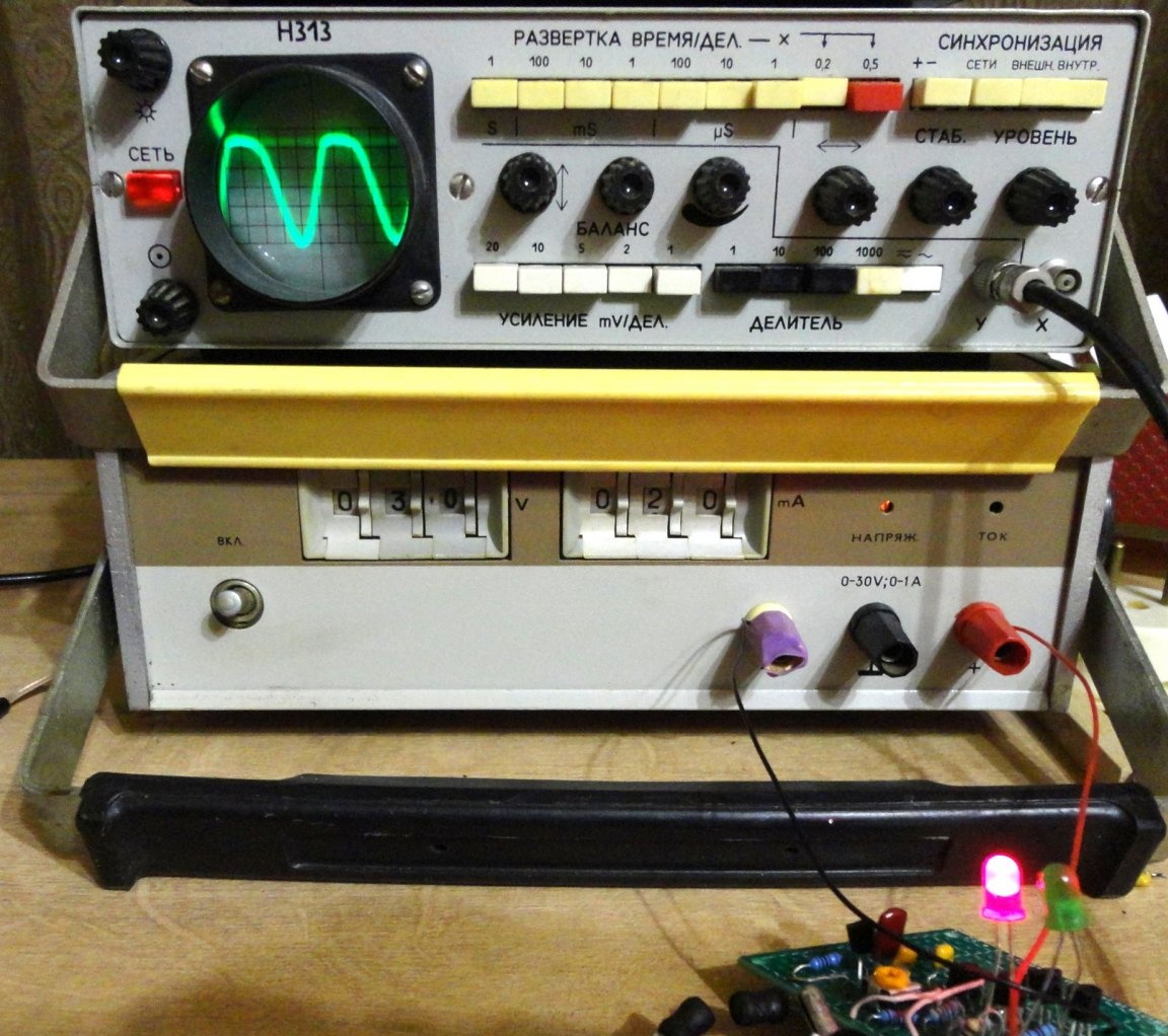
Since the circuits I found on the Internet use coils with different inductances, the idea of the experiment was to make two coils with the same ratings work normally. Therefore, for starters, the circuit was assembled and tested on a breadboard. Configured using equipment from the time of the USSR.
Schematic diagram of the device, according to the parts used.
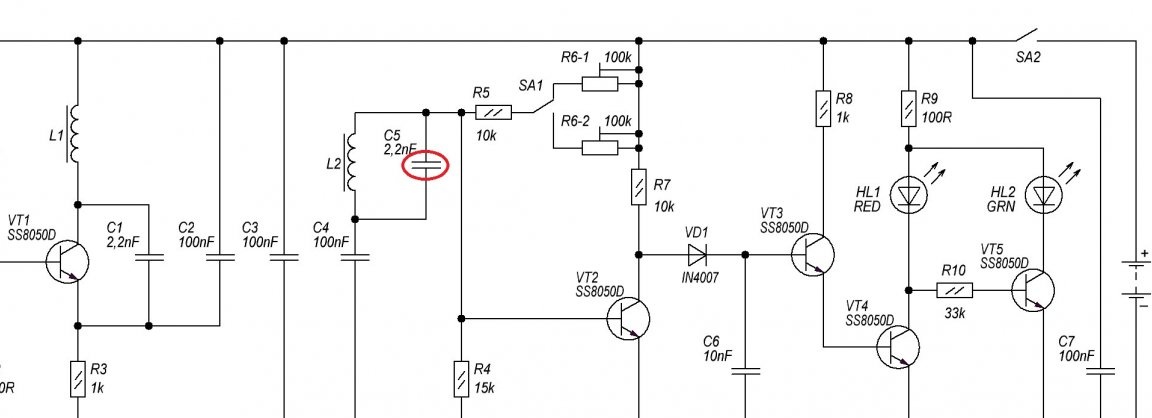
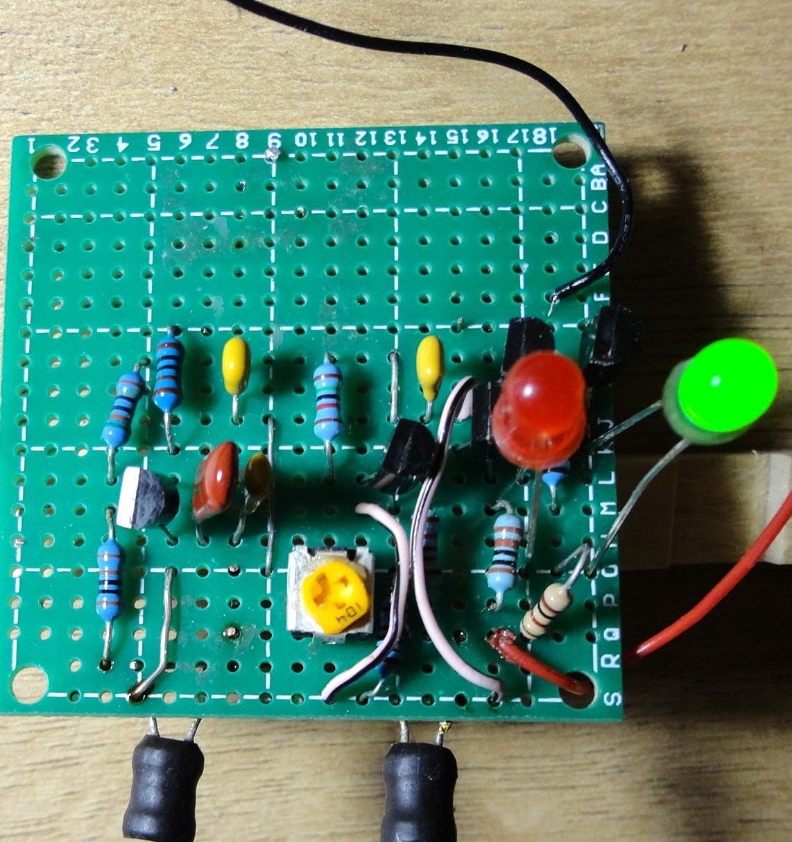
In the circuit, coils from two identical ERA fluorescent bulbs were used (I have been lying around for a long time, I use LEDs). Because I didn’t have an LC meter at hand, and I didn’t want to calculate the parameters in other ways, I don’t yet know their inductance.
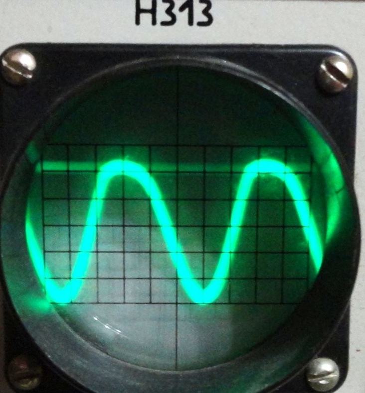
The descriptions found on the Internet of similar device circuits indicated different operating frequencies from 30 kHz to 120 kHz. By selecting a frequency-setting capacitor C1, it was possible to achieve a sine wave with a relatively regular shape on the radiating coil L1. The operating frequency is about 91kHz.
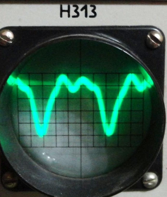
At the receiving coil L2, the signal had distortions in the form of an uneven sinusoid and “zyuki” on it. Or due to mutual interference, or due to the appearance of harmonics (did not delve deeply).
Using the “scientific poke” method, a capacitor C5 (which is absent in similar circuits) was installed parallel to the receiving coil, based on the idea of C5 = C1. Which adjusted the receiving LC circuit to the operating frequency. As a result, the signal amplitude increased at the receiving coil and the shape of the sinusoid was leveled, which significantly increased the sensitivity of the device.
The distance between the coils was chosen to be minimal, at which there is no strong direct interference between the coils, provided that there is no nearby closed conductor (for the convenience of checking relatively short anchors).
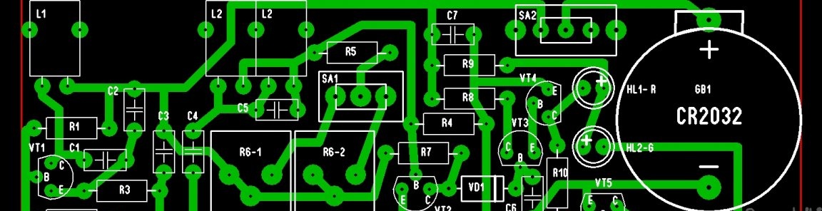
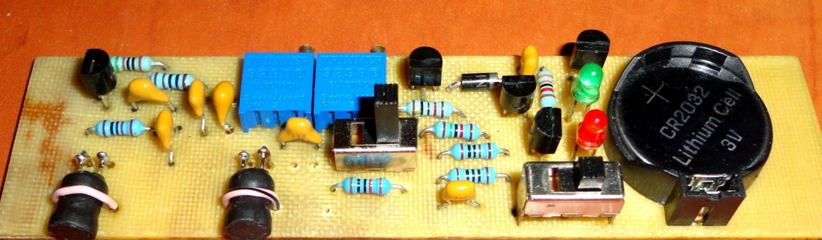
The circuit board was made with the possibility of installing coils at a distance of 21mm and 27mm between their centers (for the convenience of a possible experiment with different coils). Also, free fields are left on the board for the convenience of mounting the board in the case.
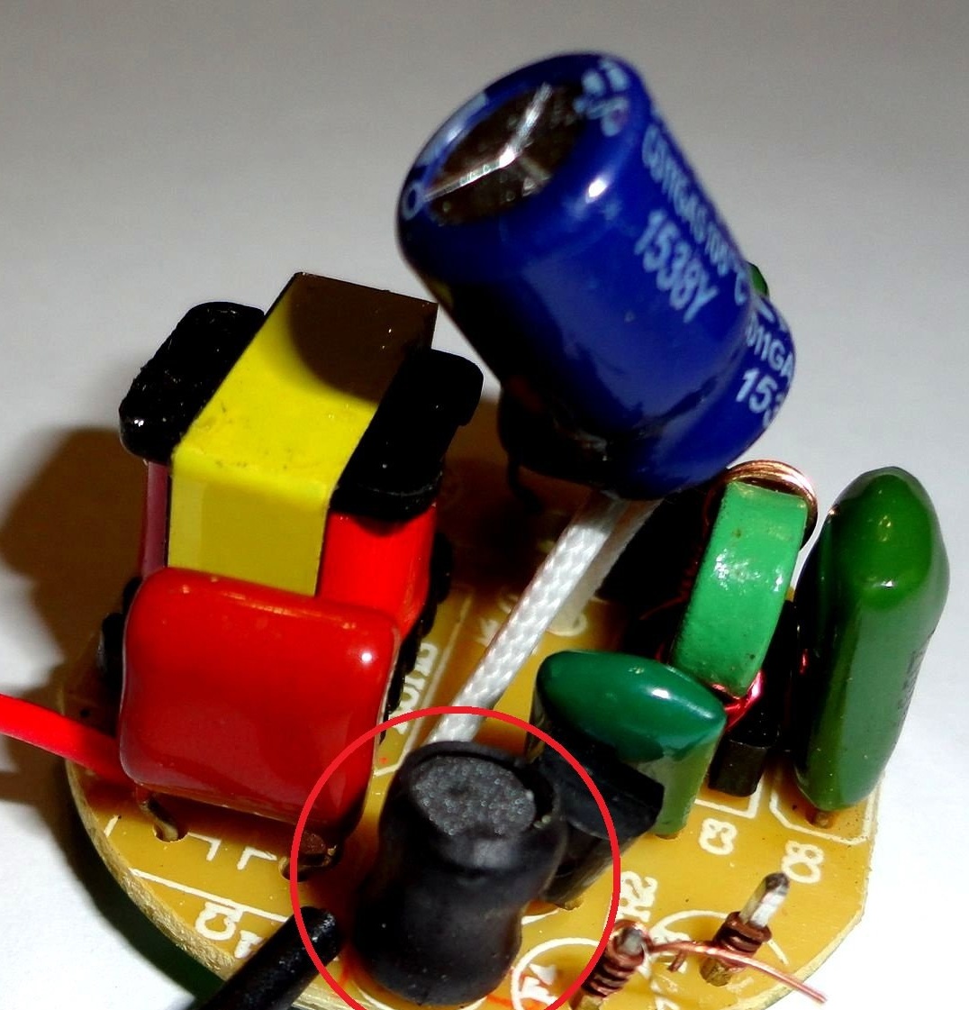
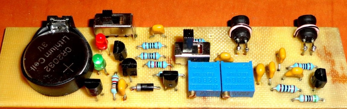
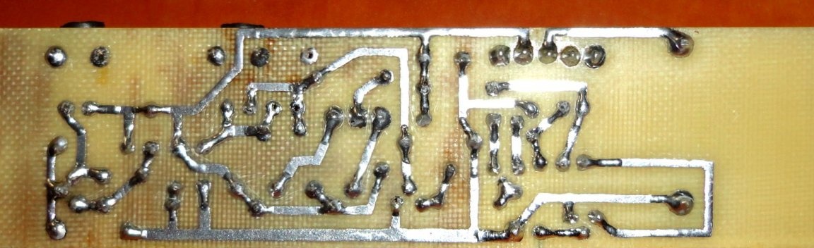
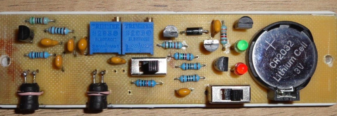
The printed circuit board is made on a piece of one-sided foil fiberglass with dimensions of 109x28mm.
Mounting on the board is not very presentable, because I used a piece of fiberglass, lying around with me since Soviet times. Apparently from time to time, strange stains and brown spots formed inside him, which confused me greatly, but did not affect the performance of the instrument.
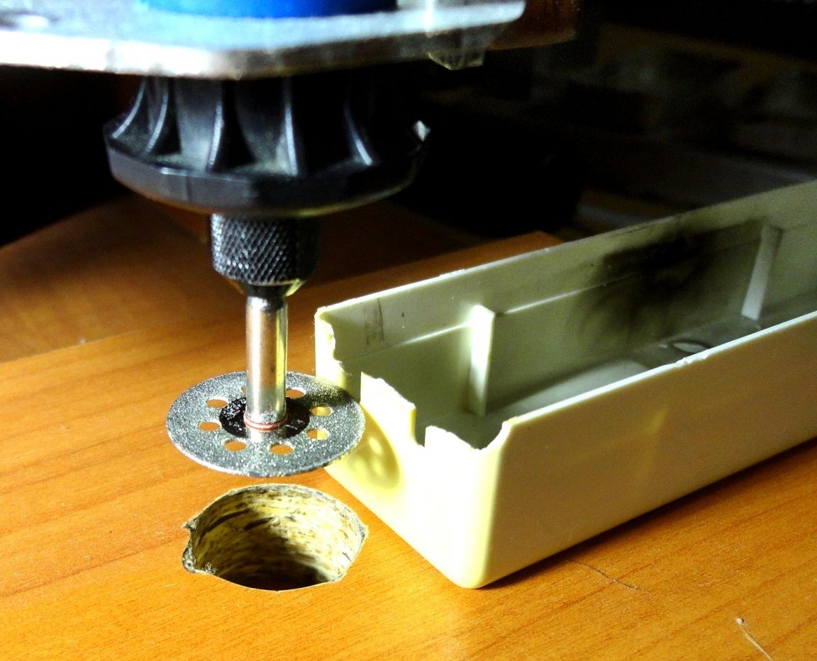
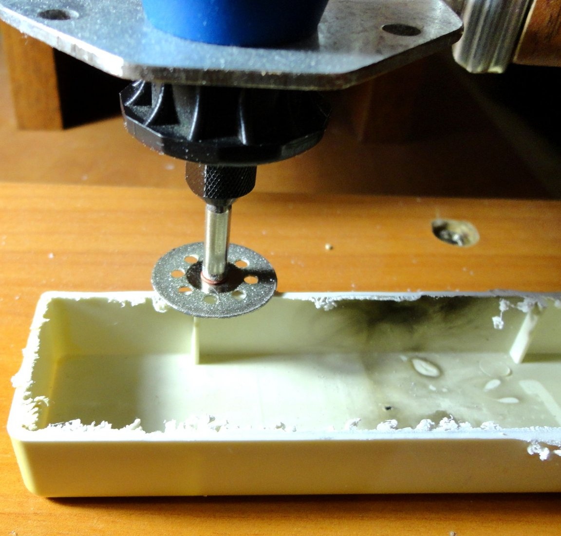
The device case was made of the case of a burned-out ballast from a fluorescent lamp.
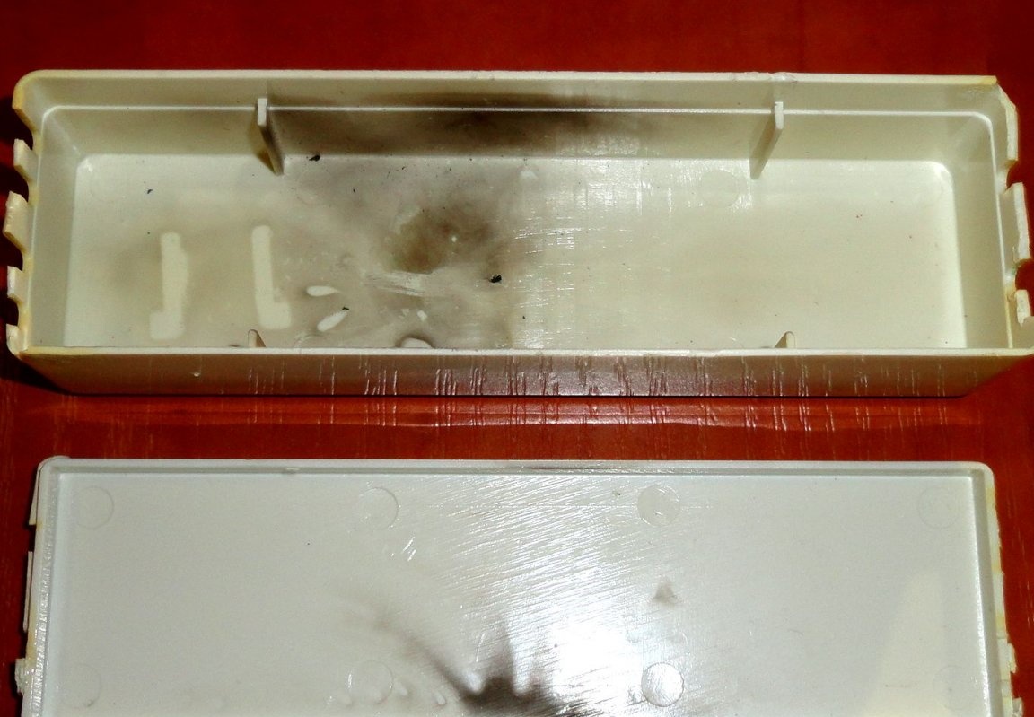
Using the Dremel MFI installed in homemade machine, the top of the case was trimmed around the edge of the wire holes. Stumbling ribs are sharpened. The bottom part of the case is fitted with files.
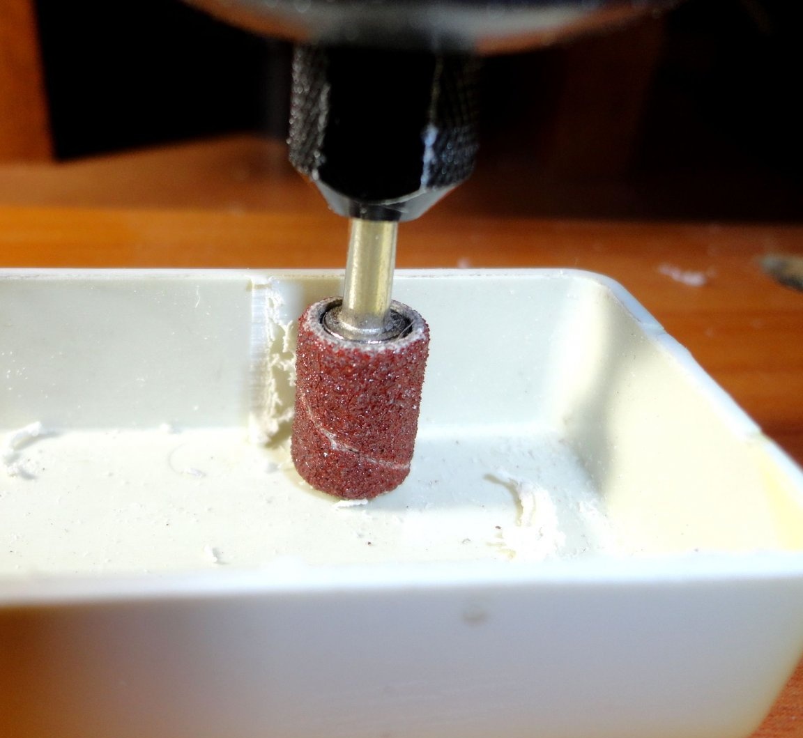
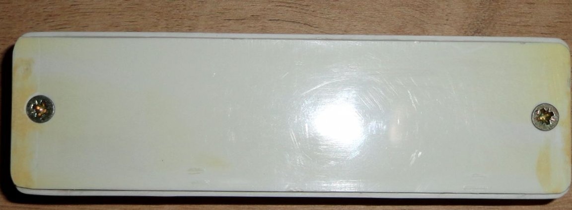
Further, plastic supports for the board were glued into the case using superglue and holes for switches, LEDs and holes for access to trimmer resistors were cut out. Then holes were drilled for 3mm screws for fastening the case.
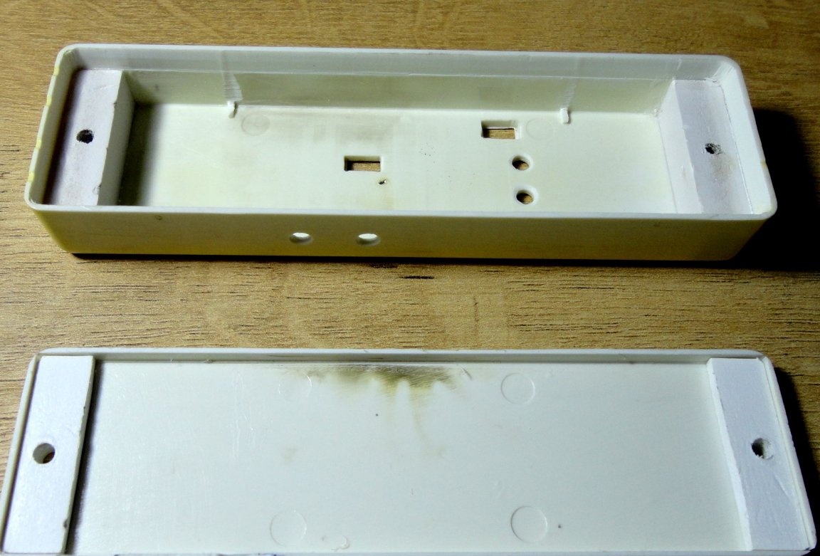
As a result, we got a rather convenient case with dimensions 113x33x17mm. Which is easily disassembled to replace the battery. The adjustment holes can be sealed with a piece of electrical tape.
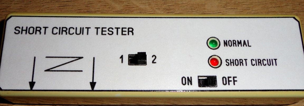
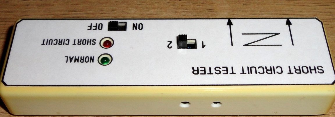
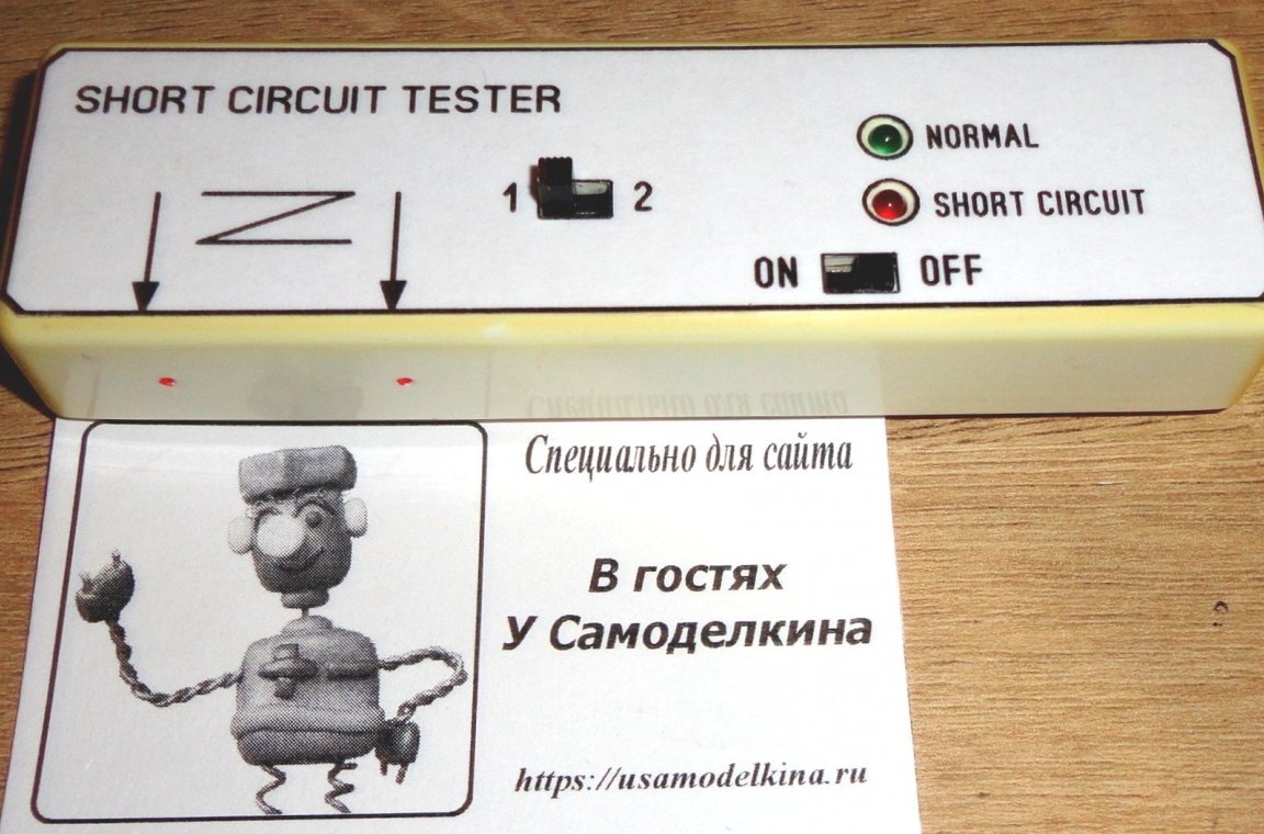
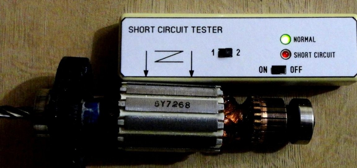
For ease of use, the arrows on the sticker indicate the locations of the centers of the inductors. Red dots on the case indicate the centers of the coils.
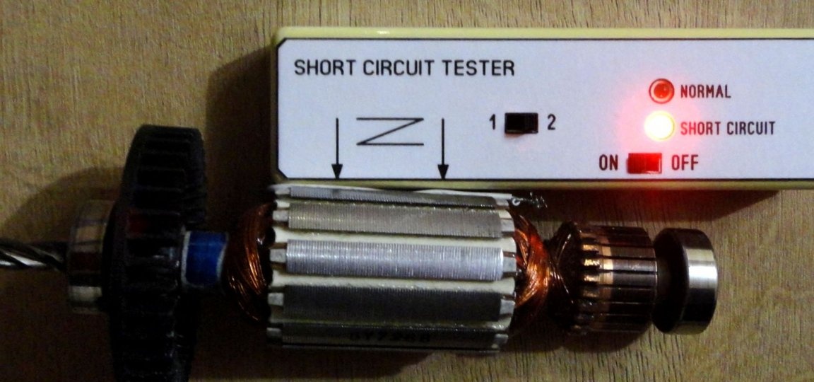
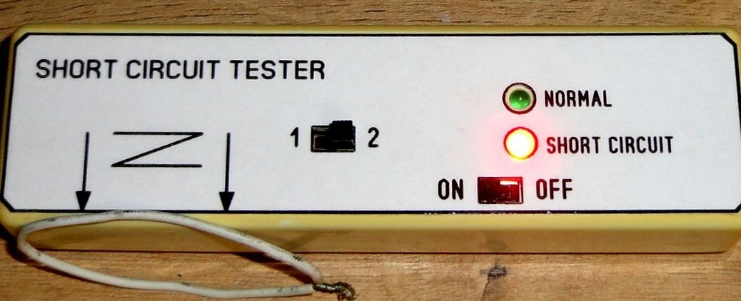
First, the tester was tested at home on an existing anchor, where a closed loop was imitated with a piece of wire. Also, the device responds perfectly to any piece of a closed wire (i.e., without a core). The device is very sensitive and responds to any closed conductor including a spectacle frame, key ring, etc. Therefore, it is very convenient to have two pre-set sensitivity ranges.
Also, the results of checking the anchors with this instrument were compared with the results obtained on specialized Bosch equipment in a workshop.
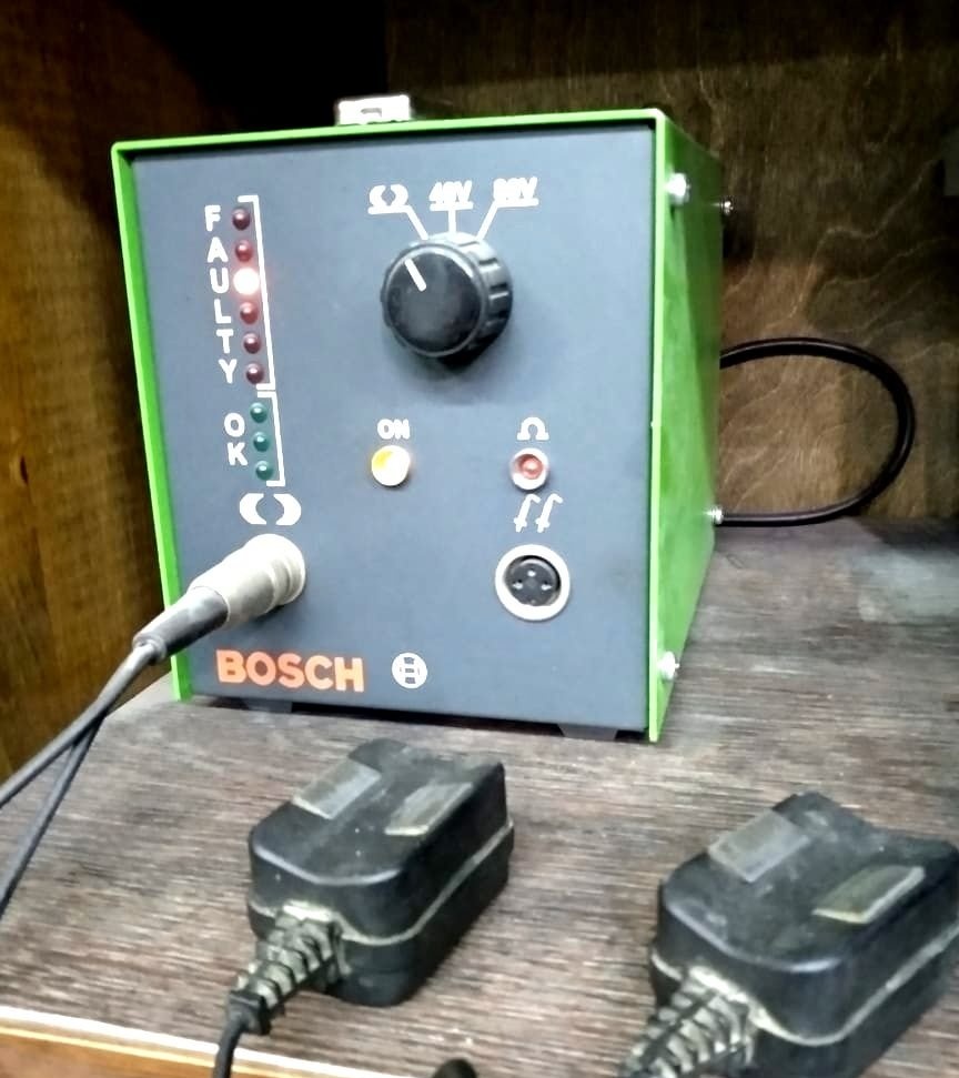
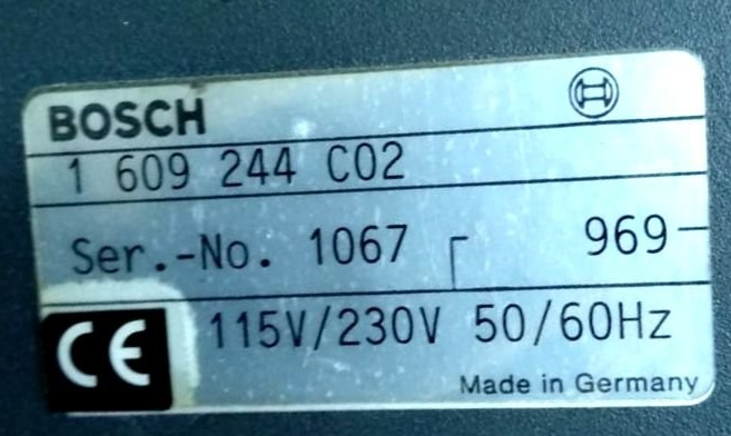
I was very pleased with the results of the comparative diagnostics of anchors in the short circuit. they coincided completely. The tester confidently showed the presence of short-circuit on the "killed" anchors and did not show false positives on the "healthy".
After testing in the workshop. Experimenting with a ready-made appliance, an interesting opportunity was found to configure not only two sensitivity modes of the appliance, but also two different operating modes:
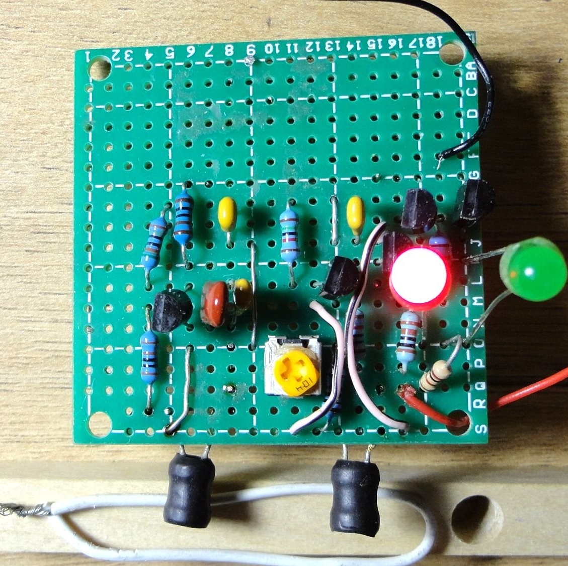
1. When turned on, green is lit, when checking a “healthy” anchor, green continues to light, in the presence of a short circuit at the anchor, red lights up, while it responds to a simple piece of a closed wire, does not respond to a metal surface.
2. When turned on, red is lit, when checking a “healthy” anchor, it lights up and green, if there is a short circuit at the anchor, red lights up, while it does not work on a simple piece of a closed wire, it reacts to a metal surface, lights up green.
In the workshop, the device was tested in the first mode.As it turned out, thanks to the presence of a switch and two tuning resistors, the device can be configured either to two sensitivity levels or to two different operating modes.
If something is missing in the description, I hope these nuances can be considered in the submitted photos. I apologize in advance for possible errors and typos.
If you need additional information, write to the post office, I will try to be sure to answer. Feedback, ideas, suggestions for improvements to the design and comments are very welcome.
January 2020