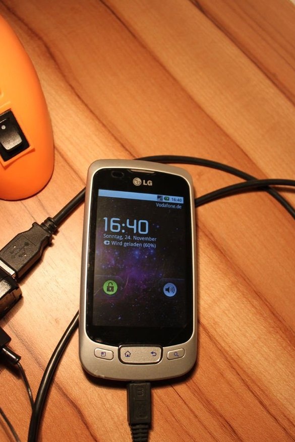
Forgot your mobile adapter? Or there’s no power outlet nearby, but still urgently need to charge your smartphone?
Let's make a USB power adapter that can be used everywhere! You will be ready for any force majeure!
Just connect this device to any rechargeable battery and charge your phone. Even an AC voltage source such as a desk lamp is fine!
Step 1: Parts List
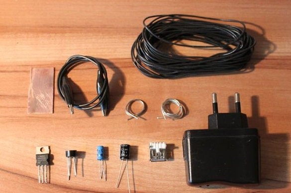
You will need:
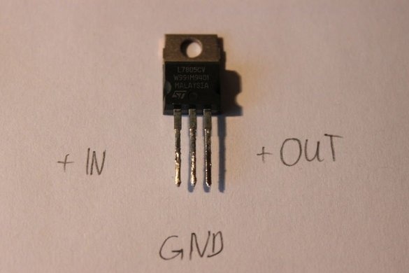
- voltage regulator L7805CV
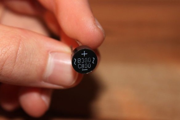
- rectifier, min. 1 A
- capacitor, min 50 V, 0.1 uF
- capacitor, min. 50 V, 220 uF
- A female USB connector, for example, from a USB charger
- USB charger or plastic case
- copper plate or cooling tile
- cable with a crocodile clip (preferably with two clips)
- tin solder
- wires
Step 2: Cooking the Case
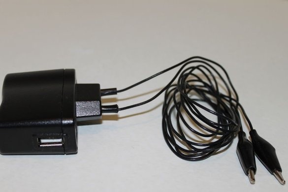
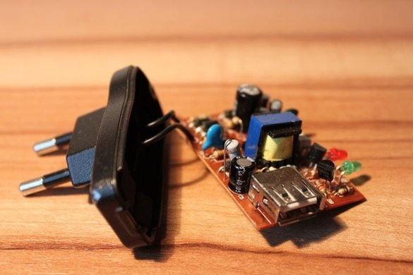
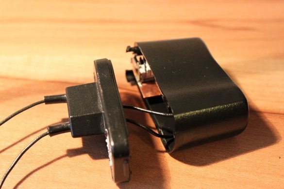
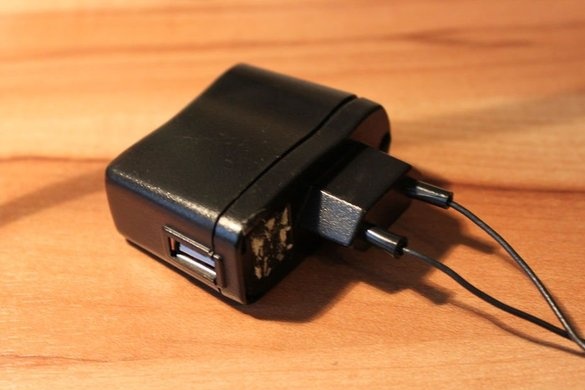
First open the case of the USB charger and cut off the wires that are connected to the male connector. Solder the female USB connector. You can use any other case, but then you have to get an additional female USB connector.
Step 3: Prepare the wires
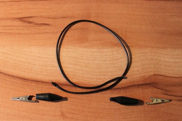
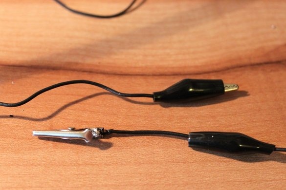
To remove crocodile clips from short wires, the protective coating must be removed. Now you can remove the clamps.
Then you need to cut off the wires with a length of 1 m and solder one crocodile clip to each wire. Remember to put on the protective cover again.
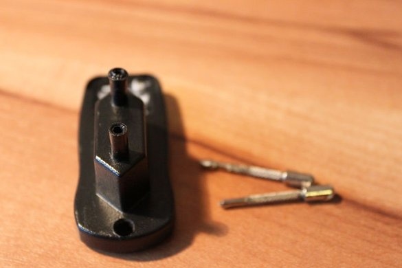
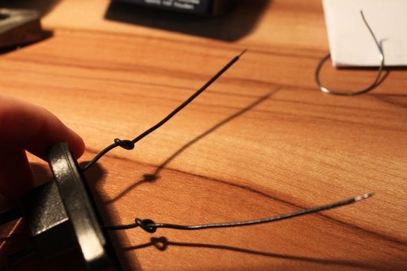
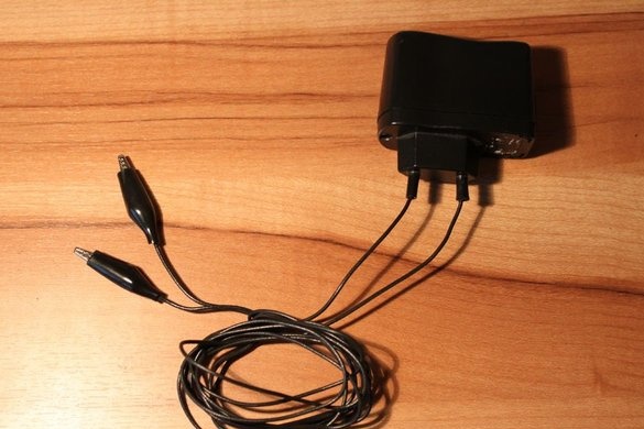
If you want to use the power adapter connector, as shown in the last photo, just remove the metal rods with pliers. Now you can push the free ends of the wires into the holes. To prevent stress on the soldered joints, tie each wire with a knot, as shown in 4 photos.
Step 4: Connect the rectifier to the voltage regulator
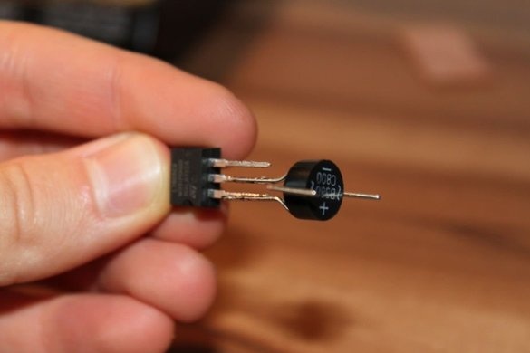
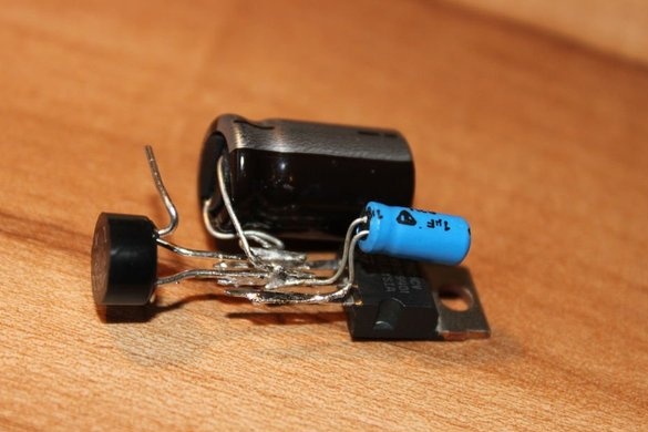
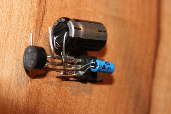
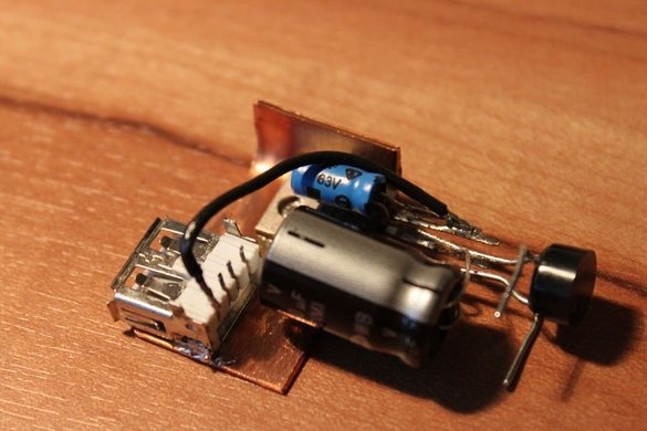
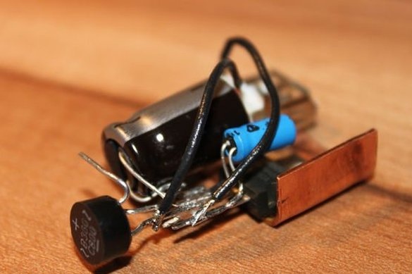
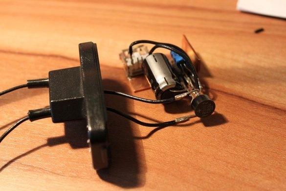
Now let's deal with the soldering of electrical components. The negative pole of the rectifier is connected to the ground (middle pin) of the voltage regulator.The positive pole is soldered to the left stud of the regulator.
Look at the photos of this step should help.
Step 5: Connect Capacitors
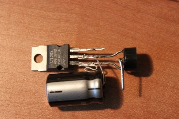
The negative poles of the capacitors must be soldered to the middle stud of the voltage regulator (ground). The positive pole of the capacitor at 220 μF is soldered to the left stud of the regulator, and the positive pole of 0.1 μF of the capacitor is soldered to the right stud of the regulator.
Step 6: Attach the Copper Plate
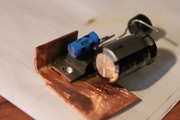
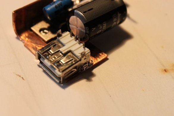
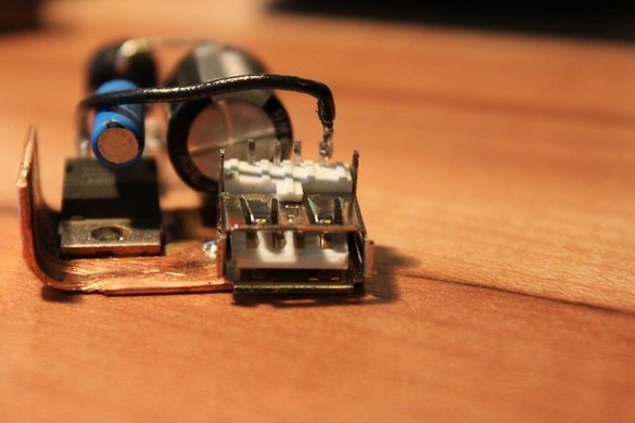
The back of the L7805CV regulator should be soldered to the bent copper plate. For best results, we recommend that you heat the copper plate with a soldering iron and evenly distribute the solder on the surface. Quickly attach the back of the regulator to the copper plate. The same procedure must be done with a female USB connector. Depending on which case you are using, you need to attach the USB connector accordingly.
Step 7: Connect the USB port and voltage regulator
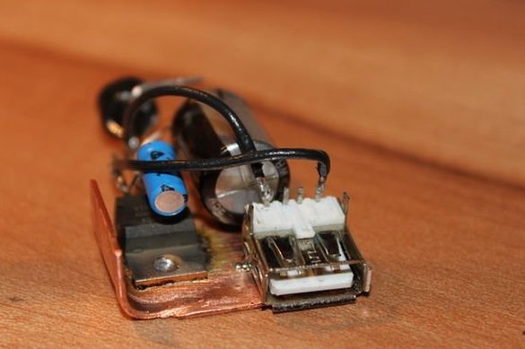
As noted in the third photo, the positive pole of the USB connector is on the right side when viewed from the front. This pin must be soldered to the right pin of the voltage regulator with a short piece of insulated wire. On the very left side of the female USB connector there is a grounding pin that you need to solder to the middle pin of the regulator with another piece of insulated wire.
Step 8: Final Touch
The free ends of the wires with crocodile clips are soldered to the free studs of the rectifier. The polarity in this case can be ignored.
Now put all the soldered elements into the case. You may need to bend the copper plate or other components so that they all fit into the case.
Your universal USB charger is ready!
Step 9: Tests
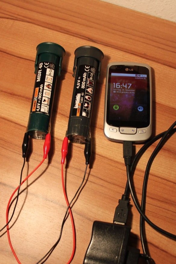
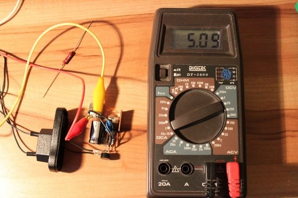
The potential of the power source connected to the universal USB charger should be at least 7V and maximum 30 V. If the potential of the power source is below 7 V, the output voltage will be less than 5 V.
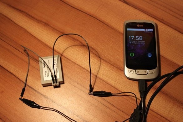
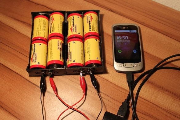
As possible power sources, you can use any kind of battery (rechargeable).
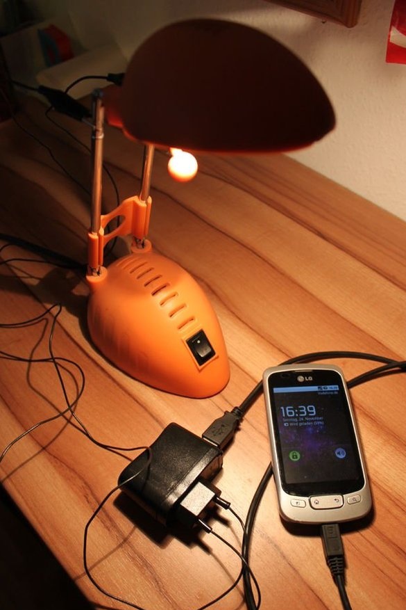
Thanks to the rectifier, the power source can even be an AC voltage source such as a table lamp. Look at the photo!
I will use it with a bunch of different batteries when I go camping.
What do you think about the possible uses for this charger? Share your thoughts in the comments!
Thanks: D

