A magnetometer, sometimes also called a gaussmeter, measures the strength of a magnetic field. This is an important tool for checking permanent magnets and electromagnets and for understanding the shape of the field configurations of non-standard magnets. With sufficient sensitivity, it can also detect magnetized iron objects. Time-varying fields from motors and transformers can be detected if the probe is sufficiently sensitive.
In this article, the Wizard will tell you how to make a simple portable magnetometer with common components: a linear Hall sensor, Arduino, display and button. The total cost is less than 5 euros, and the sensitivity is ~ 0.01 mT in the range from -100 to + 100 mT. This is better than you would expect from such a device. To obtain accurate readings, you must calibrate the instrument, and the wizard also describes this process.
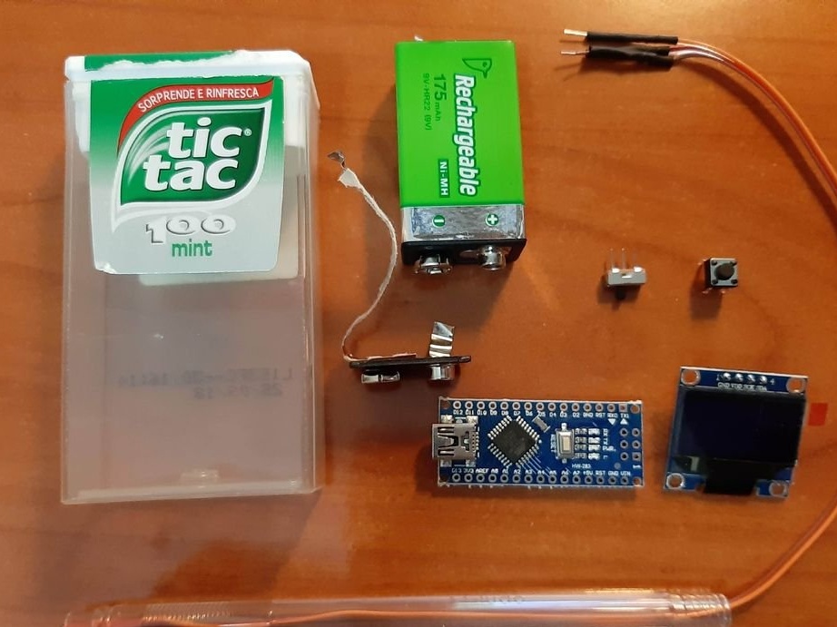
Tools and materials:
-SS49E linear Hall sensor;
-Arduino Uno;
-SSD1306 - 0.96 ”monochrome OLED display with I2C interface;
-Micro button;
-Ball pen;
-3 thin stranded wires;
-12cm thin (1.5 mm) shrink tube;
-Plastic box (18x46x83 mm);
-Switch;
-Battery 9V;
-Battery holder;
Step One: Theory
You can use a smartphone to measure the magnetic field. Smartphones usually contain a 3-axis magnetometer, but it is usually optimized for a weak magnetic field of the Earth ~ 1 Gauss = 0.1 mT. The location of the sensor on the phone is not known, and it is not possible to place the sensor inside narrow holes, such as the hole of an electromagnet.
The Hall effect is a common way to measure magnetic fields. When electrons flow through a conductor in a magnetic field, they deflect sideways and thus create a potential difference on the sides of the conductor. With the right choice of material and the geometry of the semiconductor, a measurable signal is obtained, which can be amplified and the measurement of one component of the magnetic field can be ensured.
The wizard uses a cheap and widely available SS49E sensor.
Here are its characteristics:
• Energy Efficient
• Convenient PCB interface
• Stable low noise output
• Supply voltage range from 2.7V DC to 6.5V DC
• Sensitivity 1.4mV / G
• Response time: 3mks
• Linearity (% of range) 0.7%
• Operating temperature range from -40 ° C to 100 ° C
The sensor is compact, ~ 4x3x2 mm. Measures the component of the magnetic field perpendicular to its front surface. The sensor is bipolar and has 3 pins - Vcc Gnd Out
Step two: breadboard
First, the wizard assembles the circuit on a breadboard. Connects the Hall sensor, display and button: The Hall sensor must be connected to + 5V, GND, A1 (from left to right). The display must be connected to GND, + 5V, A5, A4 (from left to right). When the button is pressed, it is necessary to establish a ground connection at A0.
The code was written and downloaded using the Arduino IDE version 1.8.10. Requires installation of the Adafruit_SSD1306 and Adafruit_GFX libraries.
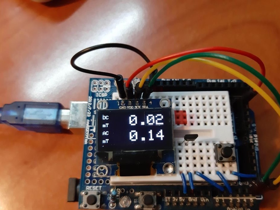
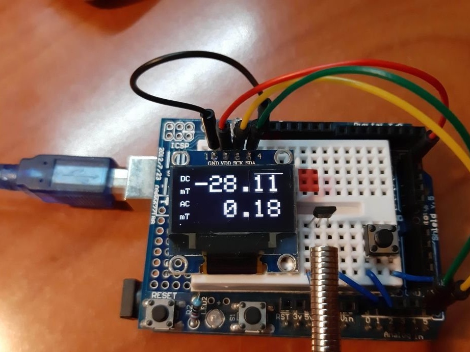
The display should show the direct current value and the alternating current value.
The code can be downloaded below.
Magnetometer.ino
Step Three: Sensor
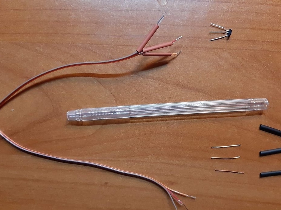
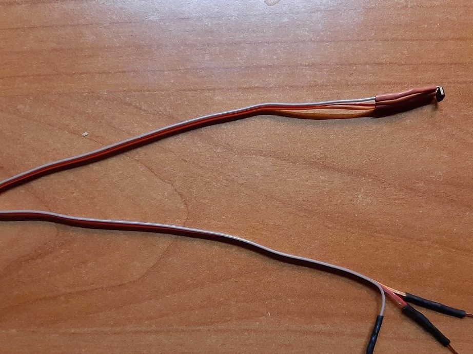
The Hall sensor is best installed at the end of a narrow tube. This arrangement is very convenient and can be easily placed inside narrow holes. Any hollow tube made of non-magnetic material will do. The master used an old ballpoint pen.
You need to prepare three thin flexible wires that are longer than the tube. Soldered the wires to the legs of the sensor, insulated.
Step Four: Build
The 9V battery, OLED screen and Arduino Nano fit comfortably in a Tic-Tac box. The advantage is that it is transparent, so the values on the screen are well read inside. All fixed components (sensor, switch, and button) are attached to the top so that the entire unit can be removed from the box to replace the battery or update the code.
The master was not a fan of 9 V batteries, they are expensive and have a small capacity. But the local supermarket suddenly sold a rechargeable version of NiMH for 1 euro each. They can be easily recharged if they are supplied with 11 V power through a 100 Ohm resistor overnight. To connect the battery, the master uses the contacts from the old 9 V battery. 9V battery is compact. From battery + served on Vin Arduino, minus on GND. An output of +5 V will have an adjustable voltage of 5 V for the display and for the Hall sensor.
The Hall probe, OLED screen and button are connected in the same way as on the breadboard. The only addition is that the on / off button is installed between the 9V battery and the Arduino.
Step Five: Calibration
The calibration constant in the code corresponds to the number indicated in the technical description (1.4 mV / gauss), but the technical description allows a wide range (1.0-1.75 mV / gauss). To get accurate results, we need to calibrate the probe.
The easiest way to create a magnetic field with a precisely defined force is to use a solenoid.
For the calculation, the following formula is taken: B = mu0 * n * I. The magnetic constant is constant mu0 = 1.2566x10 ^ -6 T / M / A. The field is uniform and depends only on the density of the windings n and current I, which can be measured with good accuracy (~ 1%). The above formula in this case works if the ratio of length to diameter L / D> 10.
To make a suitable solenoid, you need to take a hollow cylindrical pipe with L / D> 10 and wind the winding. The master used a PVC tube with an outer diameter of 23 mm. The number of turns is 566. The resistance is 10 ohms.
It then supplies power to the coil and measures the current with a multimeter. To control the current, it uses an AC voltage source or a variable load resistor. Measures the magnetic field for several current settings and compares it with the readings.
Before calibration, the sensor showed 6.04 mT, while in theory it was 3.50 mT. Therefore, the master multiplied the calibration constant in line 18 of the code by 0.58. The magnetometer is now calibrated.