The dial gauge has no problems - redrawn the scale and that's it. It is more difficult with a digital device if we increase it by an order of magnitude, i.e. 10 times, then the numbers will match, but the comma will not be in place. If 2, 3, 5 times, then the testimony will have to be multiplied by this number, the correction factor ... Let us skip all these considerations and dwell on expanding the limit to 20 A.
First, get acquainted with the characters.
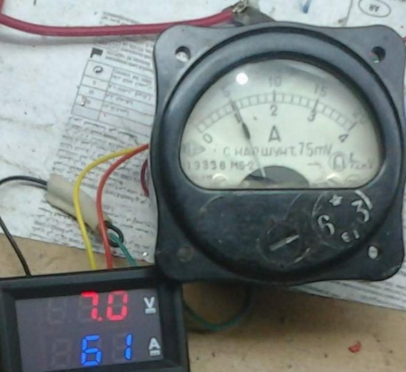
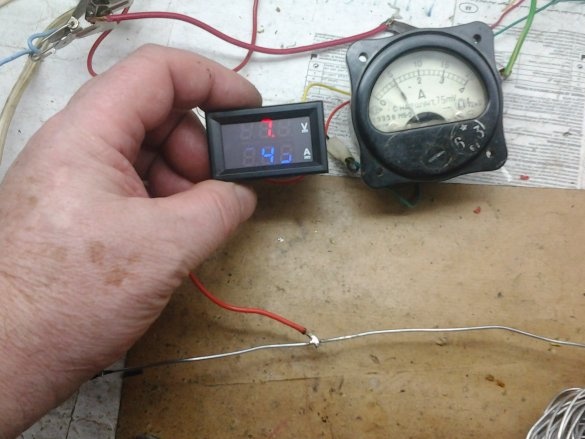
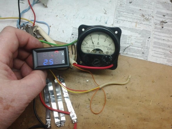
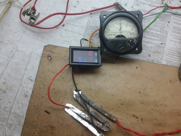
Above is an old, reliable and calibrated in the factory CLIT ammeter for currents up to 20 A. Below is our hero, DSN-VC288, which, due to the dynamic indication, is unable to photograph all the numbers in any way. I don’t have a normal camera that would compensate for this flicker, so either take a word or ...
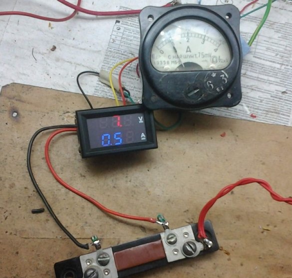
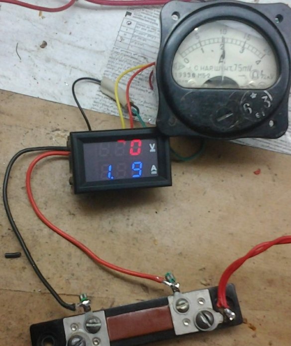
First, connect the DSN-VC288 voltammeter (hereinafter referred to as the instrument) in parallel to the standard shunt, we have 75ШСОМ3-50-0.5, give current and see what happened. The device is powered from a separate source.
The reading of 0.59 is at a current of 5 A.
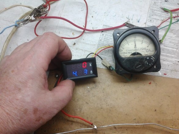
1.19 - at a current of 10 A.
That is, with a 50 amp shunt, the readings changed by about an order of magnitude, although the permissible current due to the shunt should not exceed 55 A. But the shunt is not the most common item in everyday life, let's try a piece of steel wire. The length of the measuring section is selected experimentally.
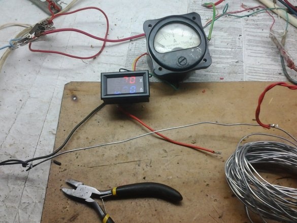
The device is not yet connected.
Current 5 A, testimony 2.49.
Current 10 A, reading 4.93, unpleasant observation - the wire is well warm, the current cannot be increased, when heated, the electrical conductivity of the shunt changes, an additional error appears. You can, of course, fold the wire two or three times with a corresponding increase in length, there will be no strong heating, but we will go further.
Let's try a shunt from a strip of metal, with the same cross section (and, accordingly, resistance), the strip has a larger cooling surface.
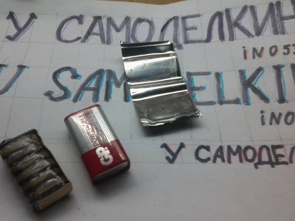
We take the case from Krona.
Everything is clear in the figures.
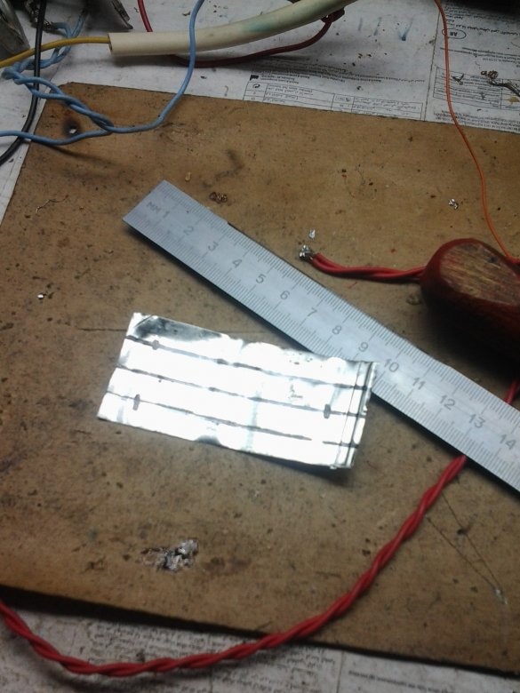
We mark, cut through.
Solder and turn it on.
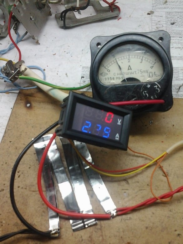
Current 5 A, reading 2.39, small, need 2.5.
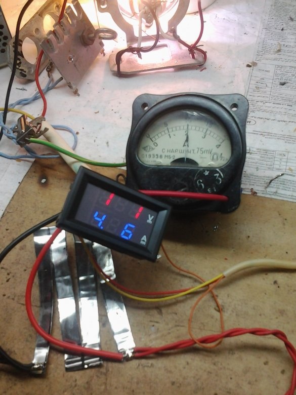
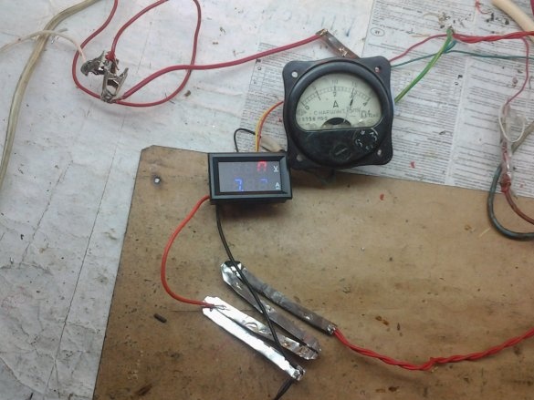
Current 10 A. The readings of the device, taking into account the correction factor (2), are underestimated, there is little resistance. Cut the strips in width.
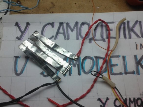
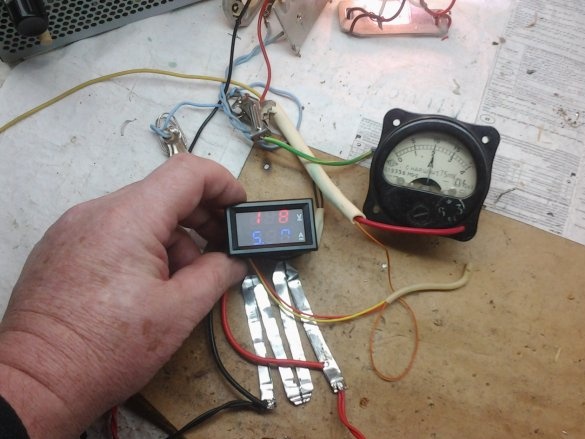
And this is what we get.The position of the test wire is selected experimentally.
Everything shows correctly (coefficient!), But a lot of voltage drops on too thin Chinese wires. We change them to more suitable ones.
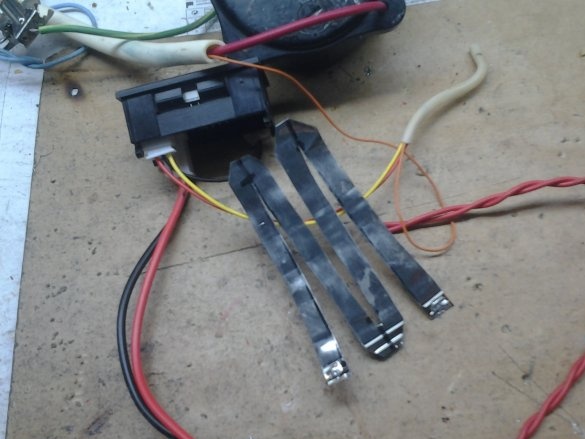
Wow, where I had to move the test lead (red from the instrument). If you now solder red thick there, then the extra piece of the shunt (3/4) can be cut off.
More current and maximum.
Still, this shunt is warm, it was necessary to cut the strip wider and longer.
Thus, at a current of 5 A, the device shows 2.5, at 10 A - 5 and at 20 A - 10. I believe that by this method it is possible to produce a shunt for any current within a reasonable range.
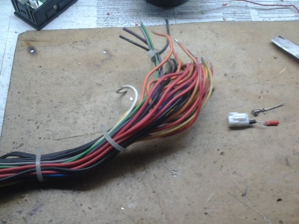
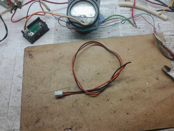
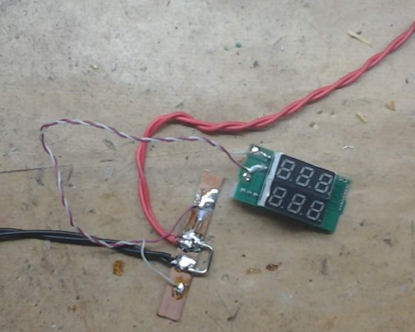
But nevertheless, a more radical way would be more correct - to remove the native shunt from the board and put an external home-made shunt (the standard is hardly suitable).
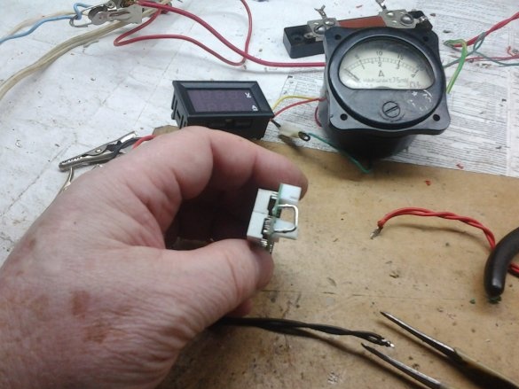
Removing the shunt from the board.
Something like this. The native shunt is sealed here, as an example.
Everything, comment.


