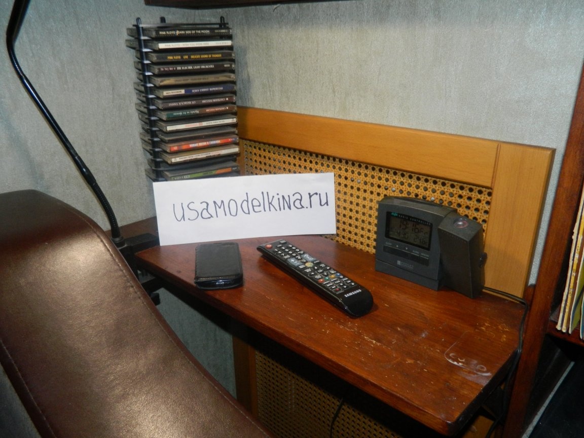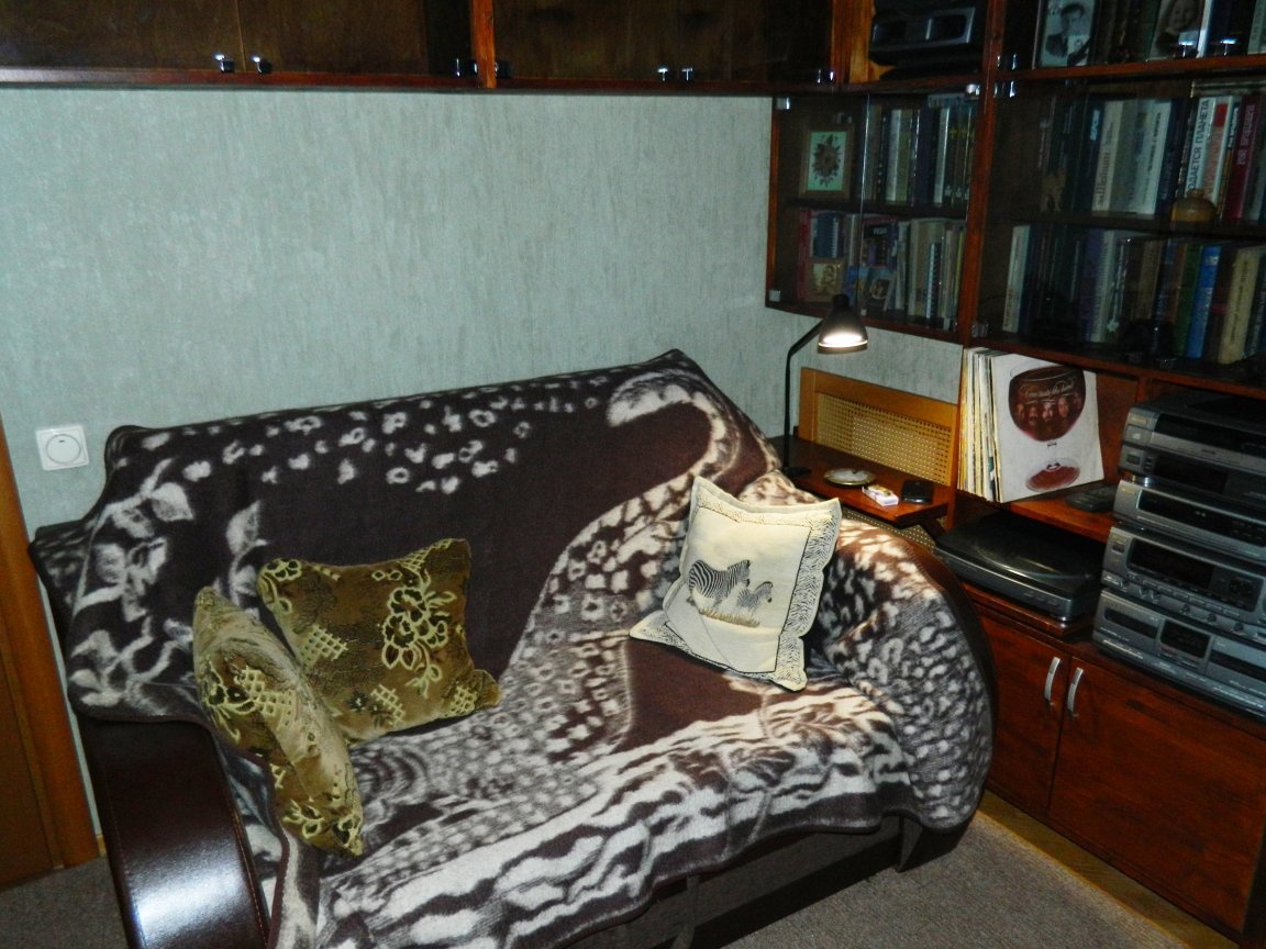
The office is made, but something is wrong in it - there is not enough table, where you can put a glass of “tea”, put the remote control on the TV. Buy ready? It will be a little crowded in the room - the area is something small (11 m²). Lay out the sofa - the table must be removed. And between the battery (by the way, constantly turned off) and the sofa there is a space of 670x300 mm.
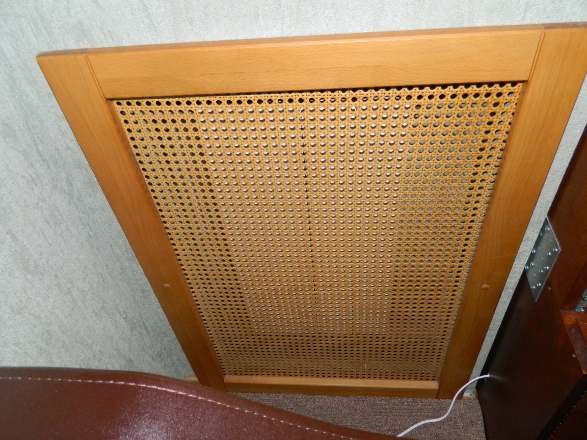
There was an idea - to make a little table-shelf, especially since there is a metal frame around the battery (to which drywall is attached). Here it is possible to securely attach the brackets of the future table to it. But the stuff is over. I had to go to Leroy Merlin.
In Leroy Merlin I bought a pine shield with dimensions of 800x300x18 mm (almost waste-free production!). And with purchased brackets, it’s just a disaster: metal is solid squalor, and wooden ones are very flimsy. I went once again to garage and found there beech rails with a cross-section of 30x12 mm remaining from the screens for the batteries (Plyushkin again failed!).
It's time to try out the JET miter saw I was once presented with.
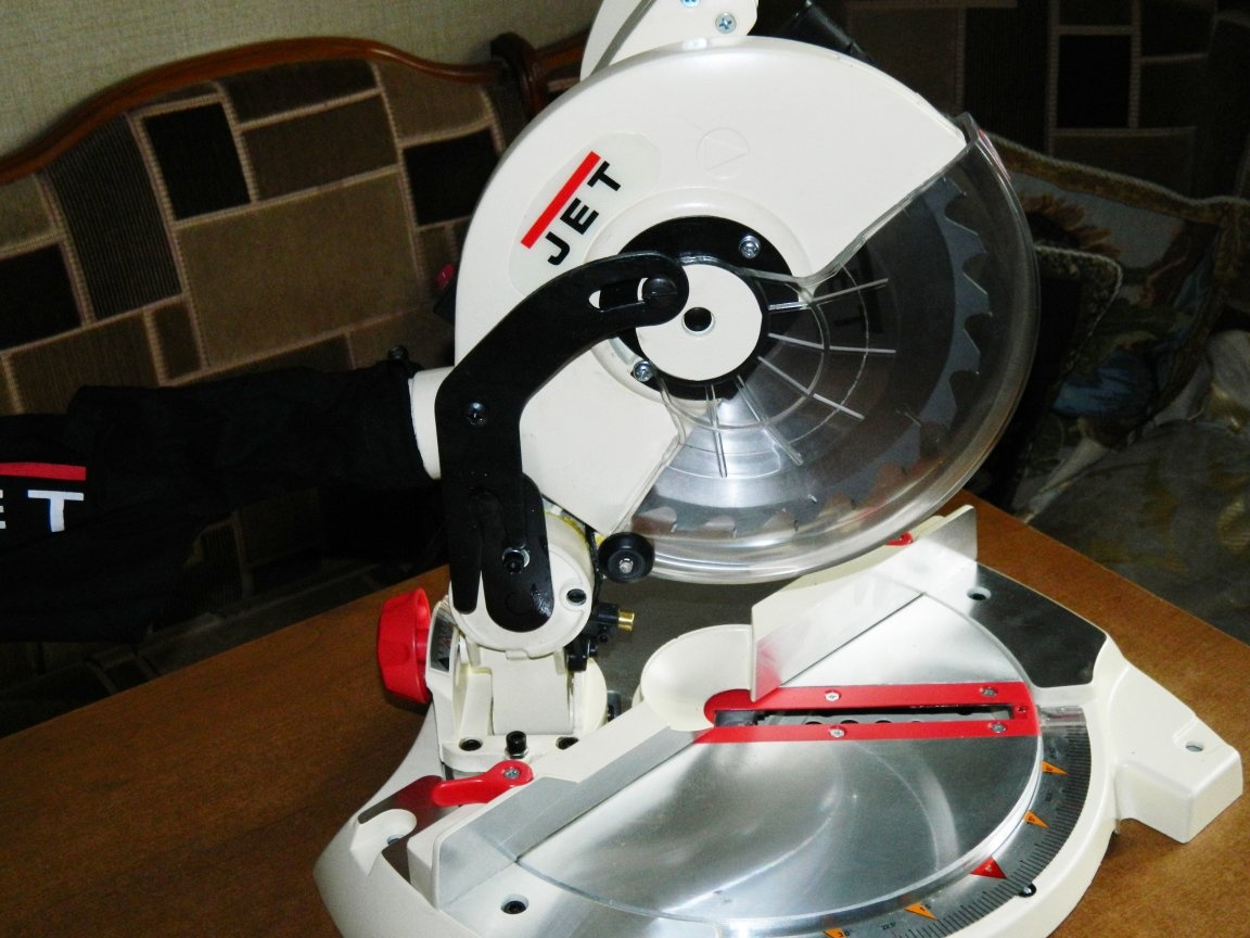
This saw even has a laser guide, by the way, well aligned (or I came across a good copy).
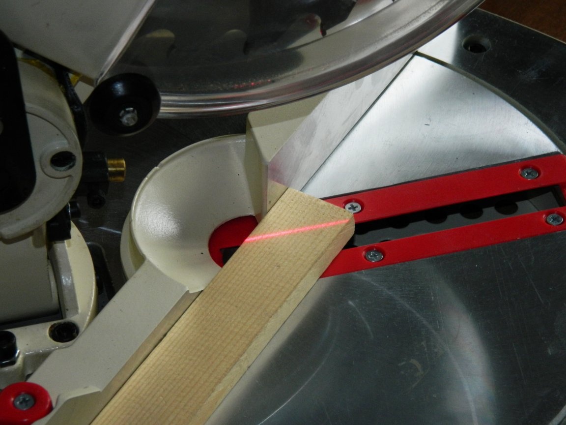
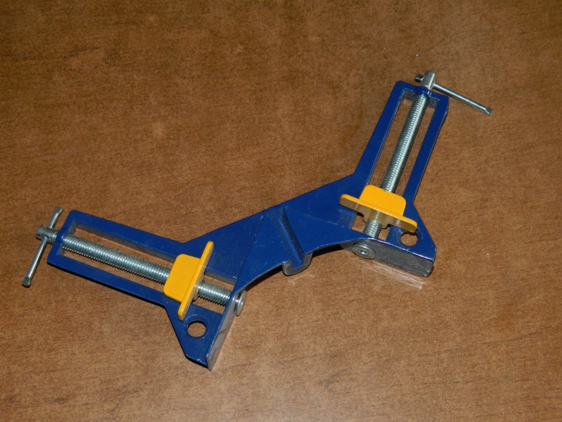
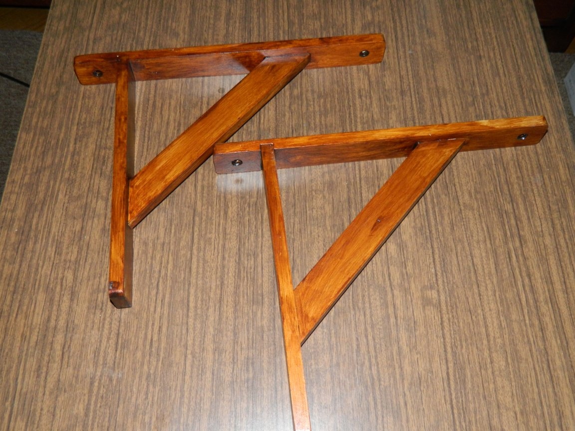
With the help of this saw, I cut the parts for the construction: two rails of 300 mm, two of 250 mm for supports and two for jibs. Small angle clamps were used to assemble the brackets.
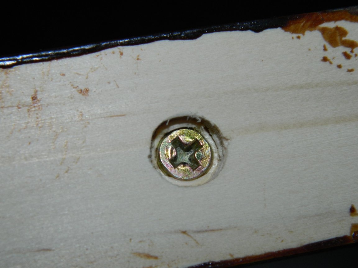
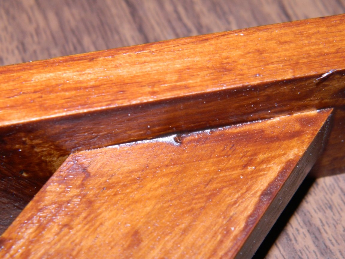
In long rails (stepping back from the end of 40 mm), I milled grooves 12x6 mm, and so that the reciprocal rail was included in the "tightness". Put in the grooves short rails for PVA and fixed with clamps. On the reverse side I fixed the assembly with screws ø3x30 mm.
Everything was done using a metal (still Soviet!) Corner. Ukosiny put on PVA and self-tapping screws.
When the glue dried (about 24 hours) removed the snap. At the base of the brackets, I drilled holes for fastening. Then he sanded off the finished products and covered Belinka with azure in several layers. It turned out pretty well - durable and beautiful.
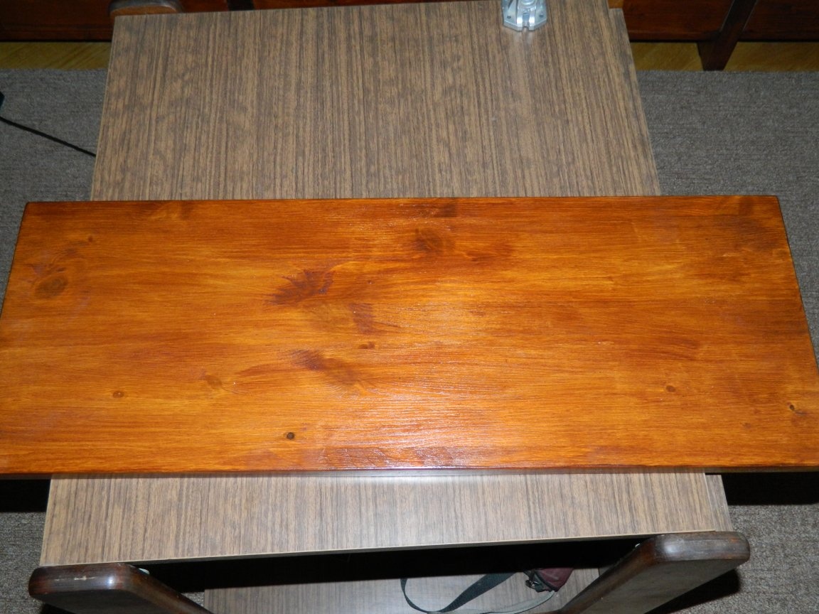
The dimensions of the countertop - 670x250 mm (pre-rounding the front corners and covering with azure).
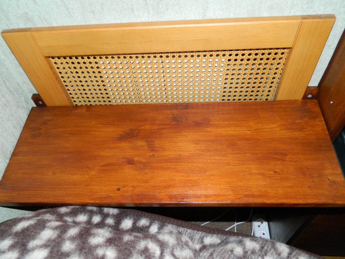
He set the brackets so that the countertop was flush with the arm of the sofa, and secured the countertop.
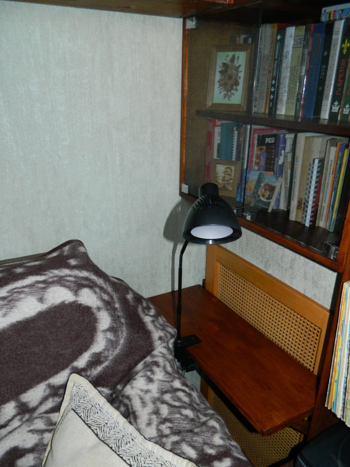
Now I had to think about lighting the rest corner. I have already purchased a LED table lamp.
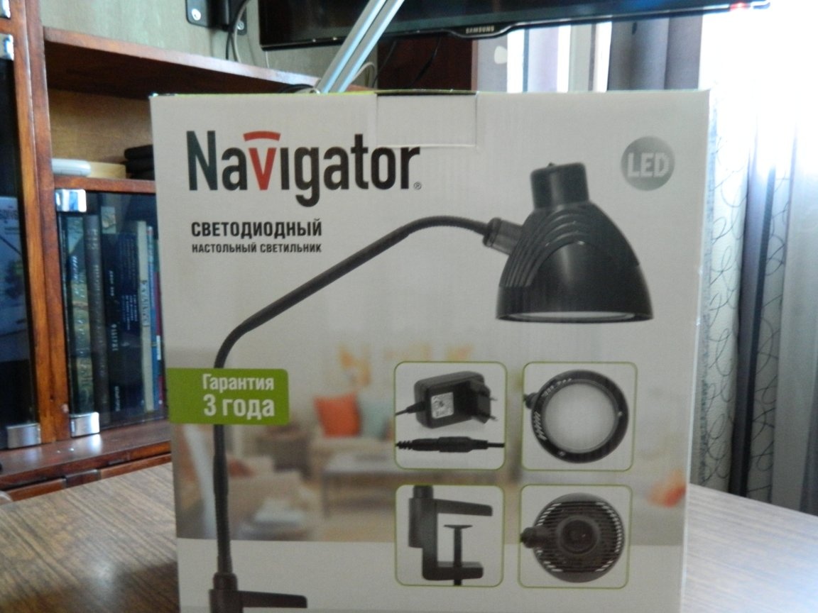
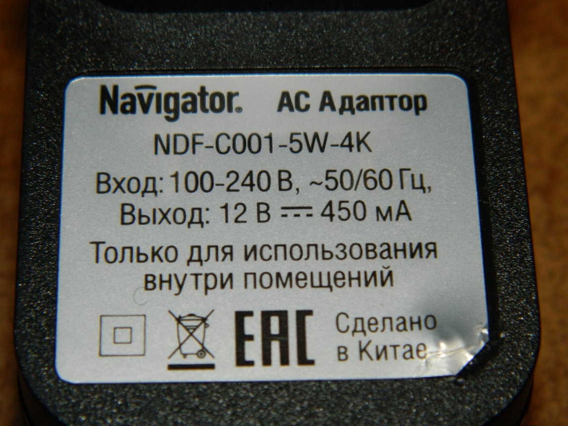
The Chinese lamp was not bad (in appearance): cheap (I gave it, in my opinion, a little more than 1000 rubles), did not take up space (mounted on a clamp), a flexible leg could control the direction of the light. Consumed a 5 W lamp, 3 year warranty. Seems not bad. I didn’t like one thing - it was powered by a unit that was constantly plugged into a power outlet. The switch switched the low voltage line. The power supply had the following characteristics: Uout. = 12 V, Iout. = 450 mA.
Despite the guarantee, I opened the lamp, picking up the sealing ring with a screwdriver and twisting out a few screws.
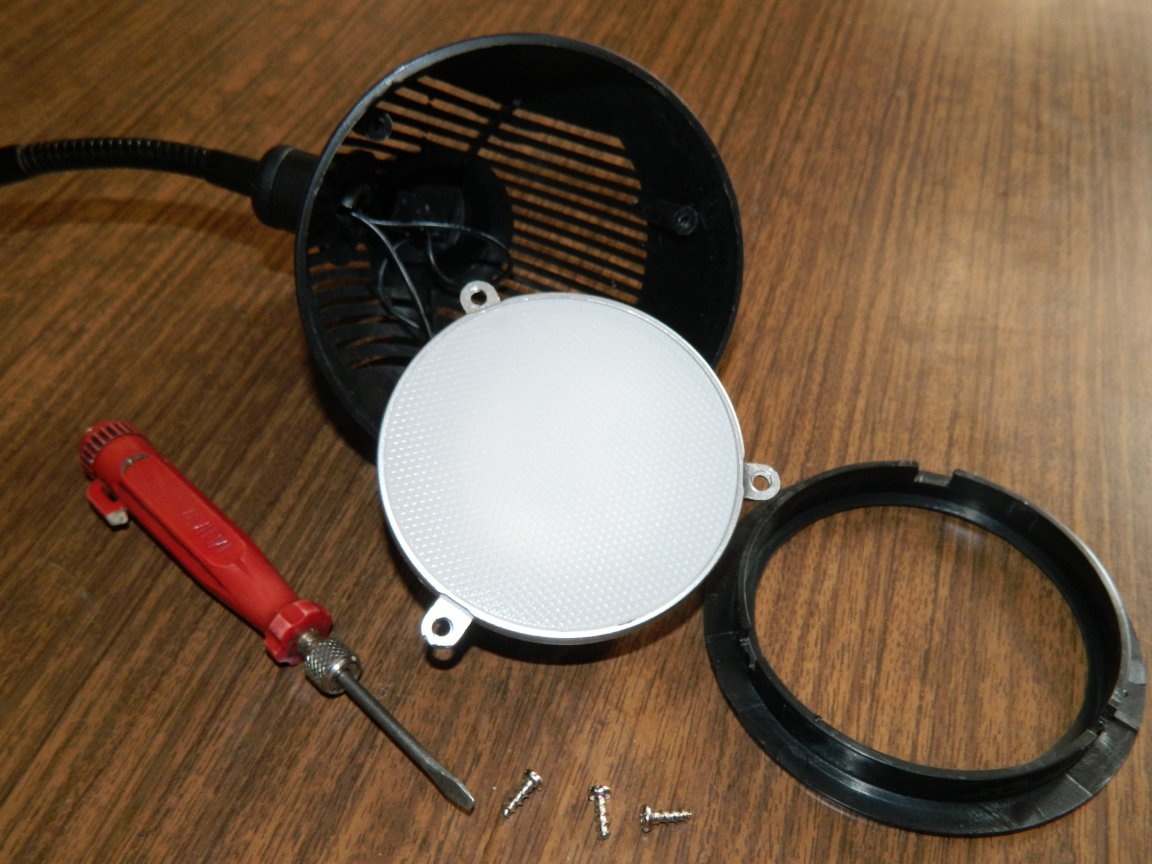
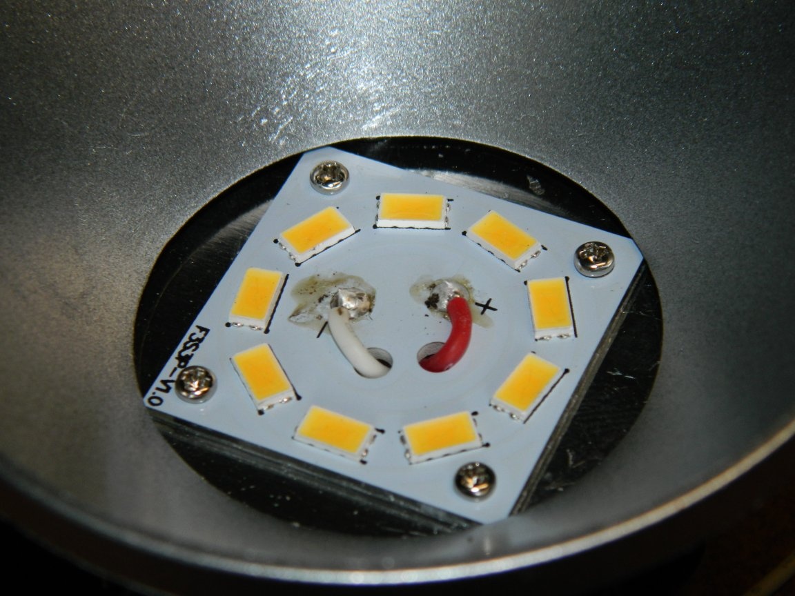
Removing the diffuser, I pulled the board out.
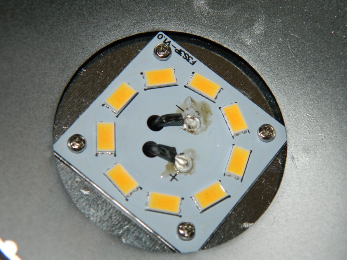
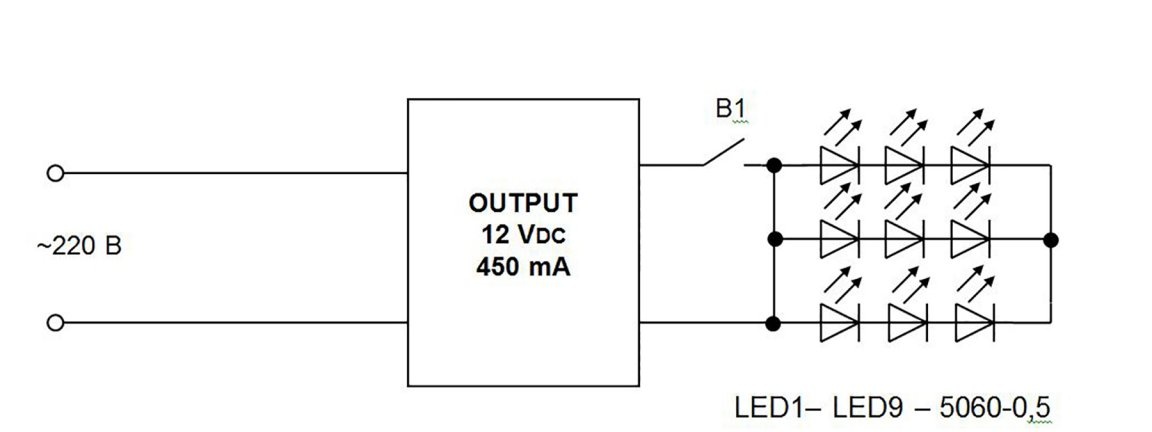
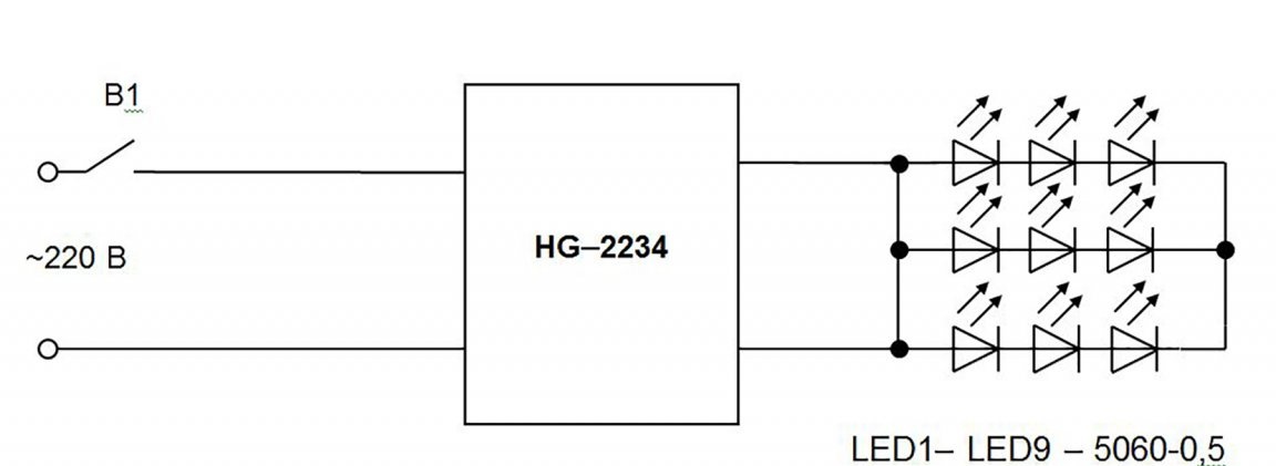
There were 9 LEDs, it is unclear how connected. In size, they were similar to super bright LEDs 5630-0.5. These LEDs have the following characteristics: Inom. = 150 mA; Imax = 180 mA; Upr = 2.9-3.6 V; Φν = 45-55 lm; 2Θ1 / 2 = 120 °; contains one crystal 20x38 mil. It looks like they were connected according to the circuit shown in figure 1.
I began to look for a suitable driver and found in the stash - HG-2234: Uout. = 6-12 VDC and Iout. = 460-500 mA with dimensions 25x17x17 mm.
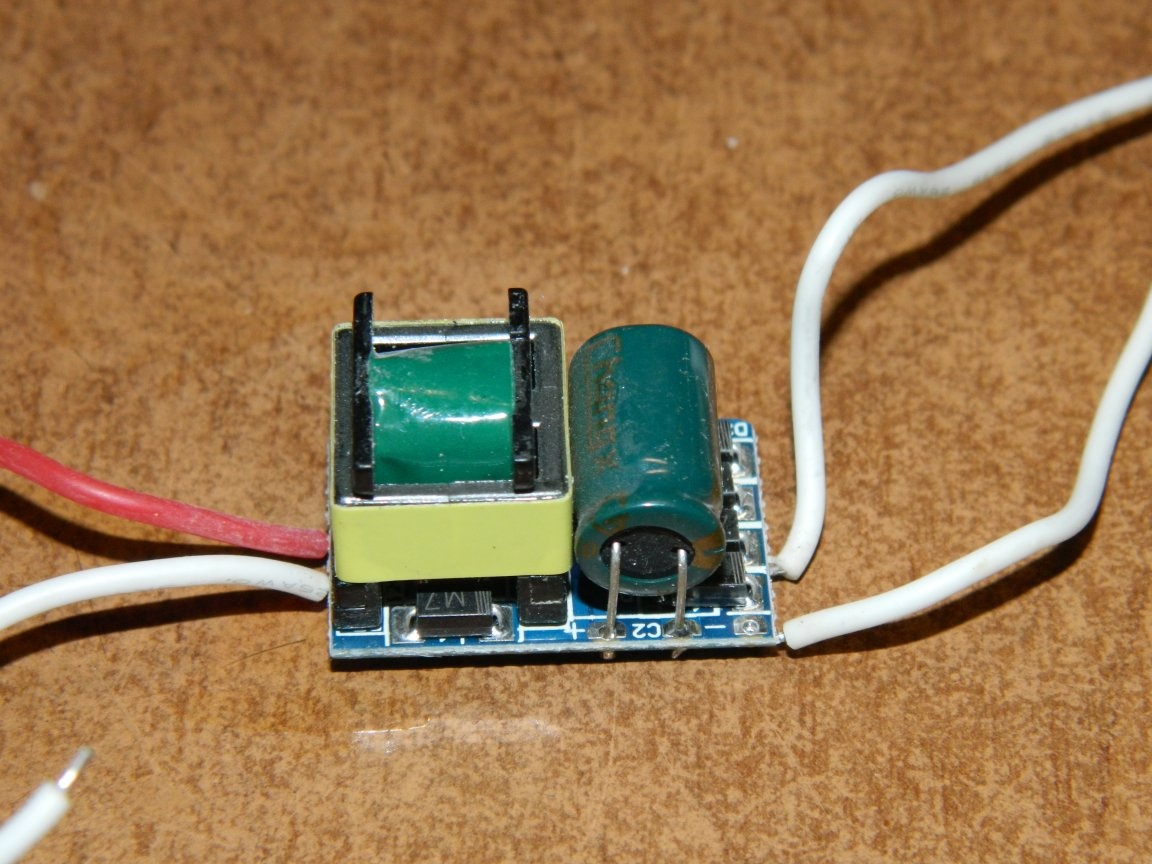
It was interchangeable with the "native" power supply. The connection diagram is shown in figure 2.
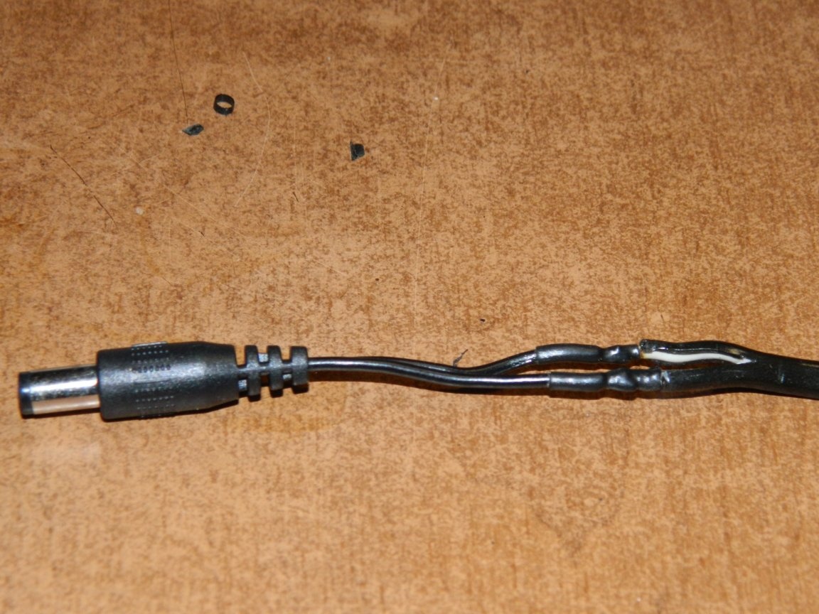
I began to remodel the lamp: first, I soldered the connector from the power supply to the network cable (otherwise it would not have crawled into the hole of the clamp securing the lamp to the table).
Then I soldered the wires from the driver to the LED board.
The driver got into a small box and was screwed on top of the heatsink with just copper wire.
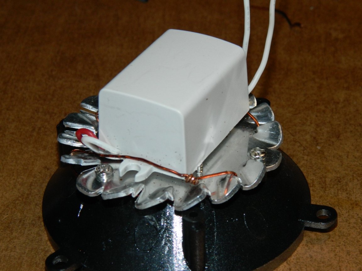
A space of about 5 mm was formed between the box and the radiator due to protruding self-tapping screws, which allowed air to circulate so as not to disturb the cooling of the radiator. Mains wires are soldered directly to the switch. Assembled the lamp and you're done!
In the off state, the lamp is completely de-energized. The brightness of the lamp increased due to the fact that the current also increased to 160 mA. The luminous flux increased to approximately 360-400 lm (and it was only about 300 lm). There is a slight warmth from the LEDs after a long lamp operation. Upgrading the lamp has benefited!