
Surely many of you have a small workshop, and are constantly expanding your own arsenal of machines. For grinding parts and workpieces used as manual fixturesand various machine tools and hand grinders.
In this article, the creator of YouTube channel “Creates DIY” will tell you how he made an orbital (or plate) grinding machine. In addition, the master implemented in it the function of tilting the grinding disc relative to the table, which greatly expands its capabilities.
This project is quite simple to manufacture, and will require a minimum of tools.
Materials
- Sheet plywood 12 mm
- The engine from the food processor
- M8 bolts, washers, nuts
- Thumbscrews
- Furniture driven nuts
- Double-sided tape
- Impregnation for wood
- PVA glue
- Wood screws
- Sandpaper.
Instruments, used by the author.
— Screwdriver,
— Forstner Drillswood drill
— Countersink drill
— Manual frezer
— Circular nozzle for hand milling
— Miter saw
— Electric jigsaw
— Clamps
— Dremel
— Orbital sander
— Svenson Square
- Roulette, pencil, marker, ruler, rule, pliers, wrenches, hammer, putty knife, scissors, knife.
Manufacturing process.
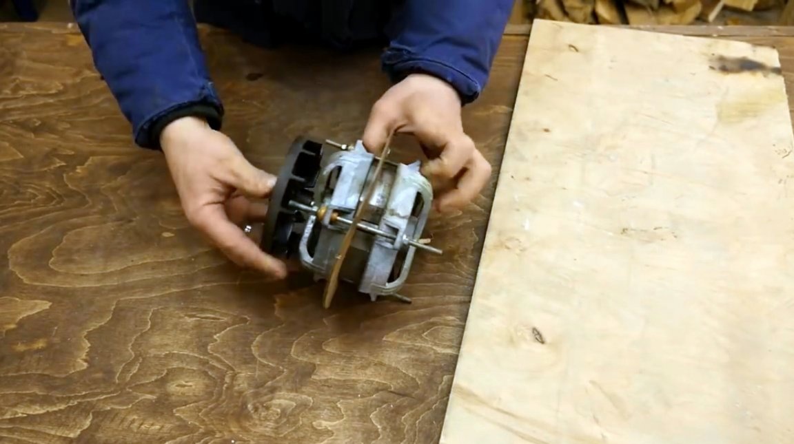
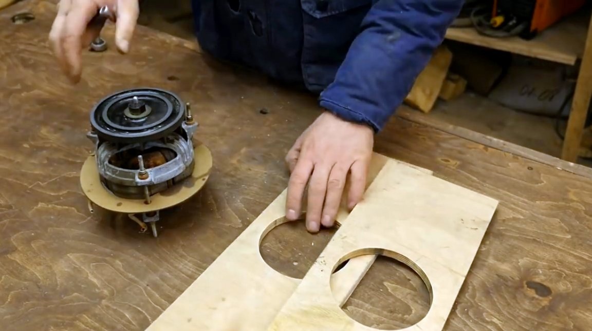
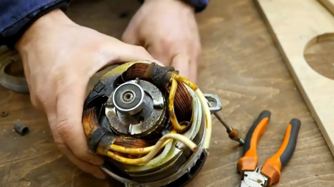
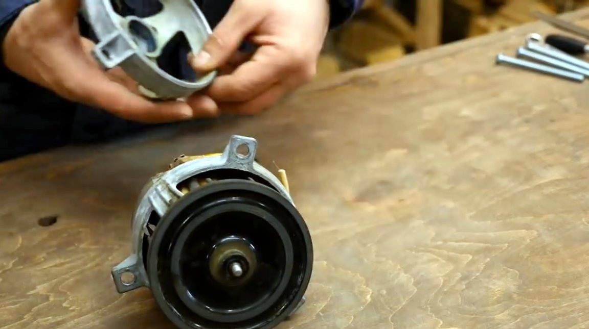
As an engine, the author will use a motor from an old food processor.
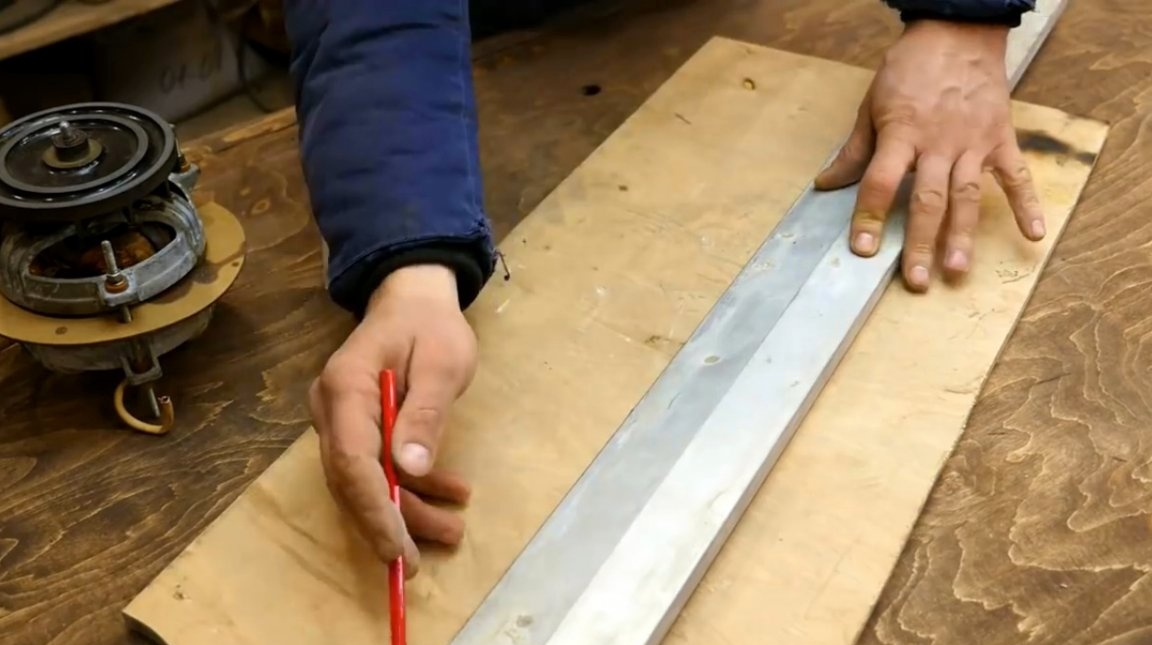
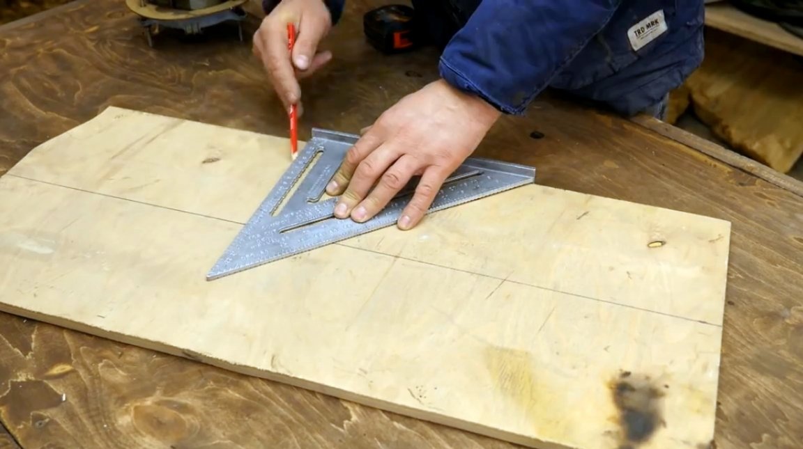
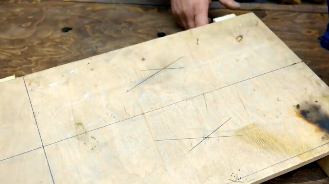
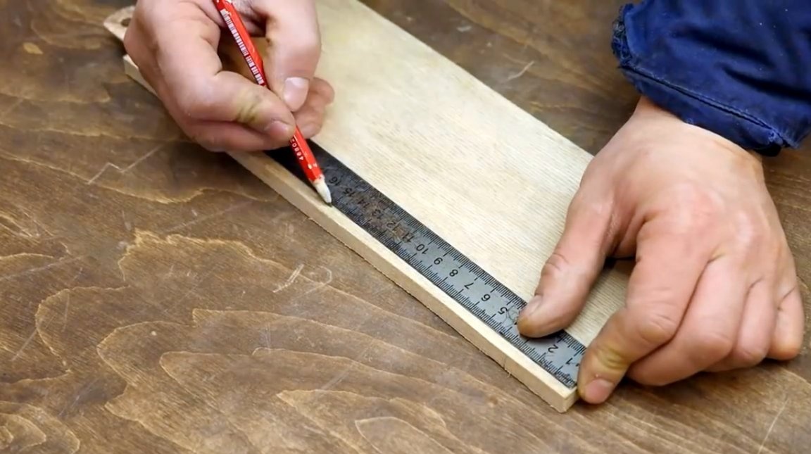
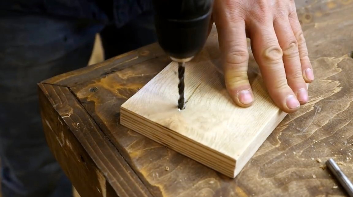
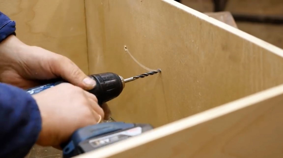
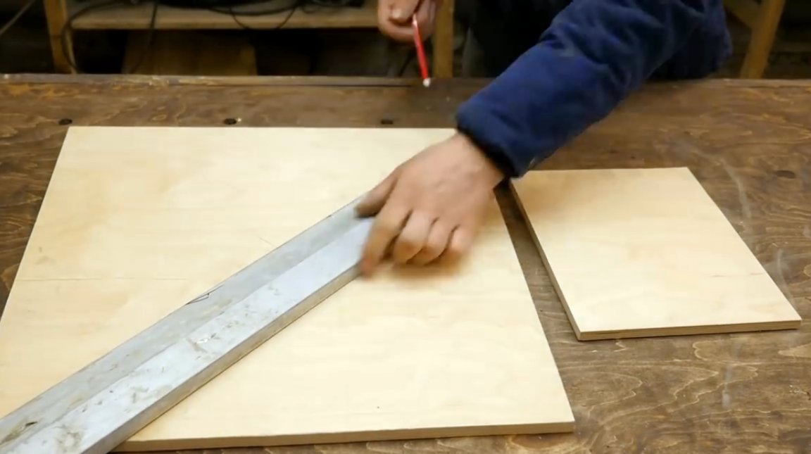
First of all, he needs to make a holder for the engine, which will also be a rotary mechanism. On a sheet of plywood 12 mm thick, he marks two identical rectangles, finds centers on them, and drills a hole with a diameter of 1 mm in them.
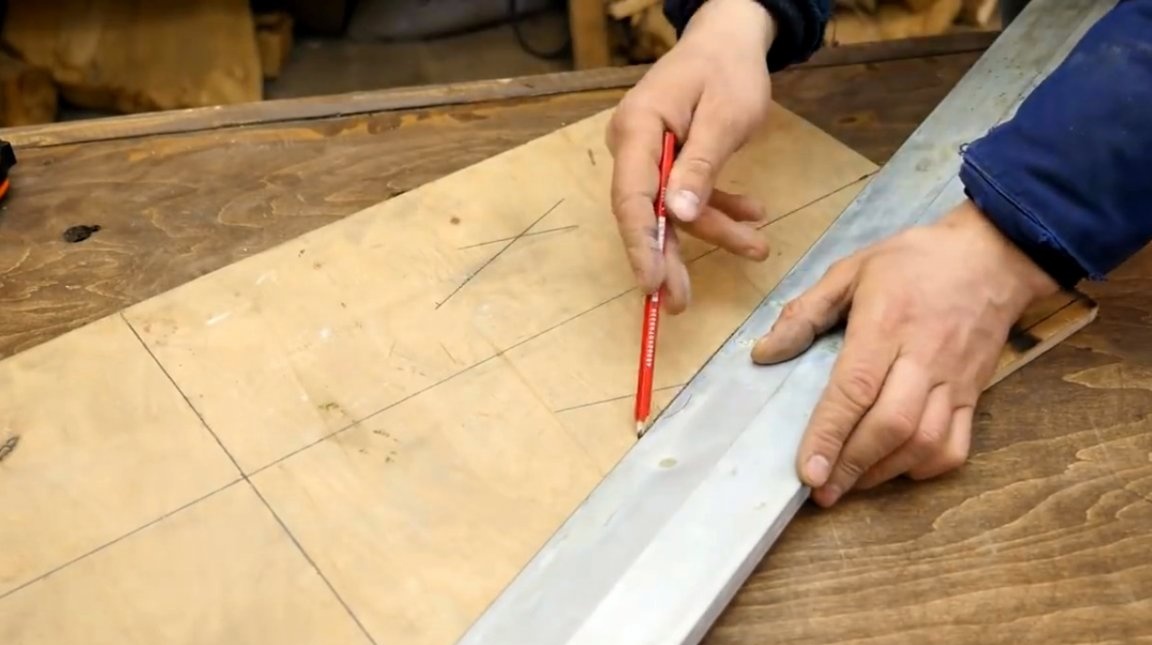
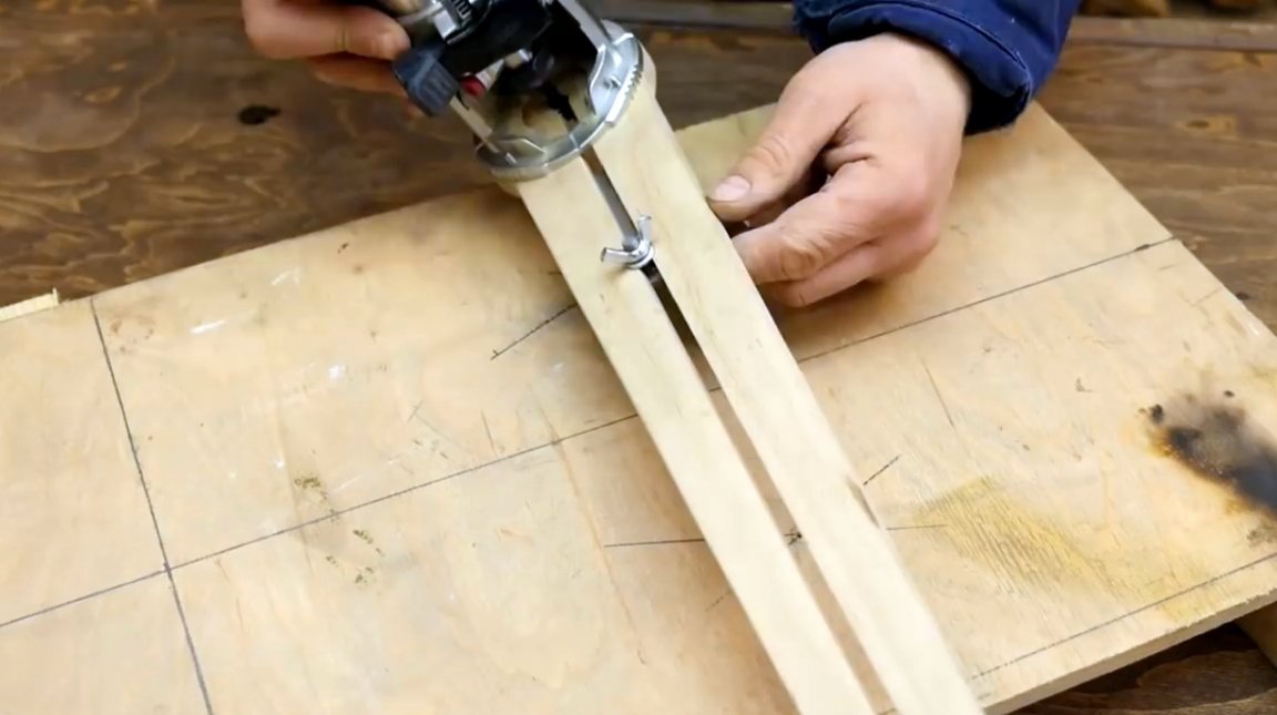
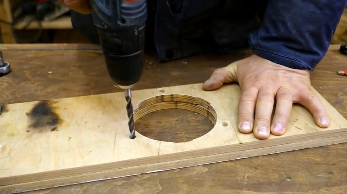
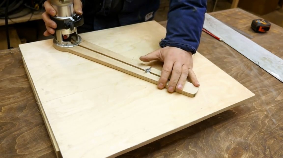
To cut circles, the master will use a special home-made circular nozzle for a manual milling cutter, the manufacture of which was described earlier in one ofarticles.
By measuring the diameter of the engine casing, and setting the compass needle, the author mills two circles in several passes.
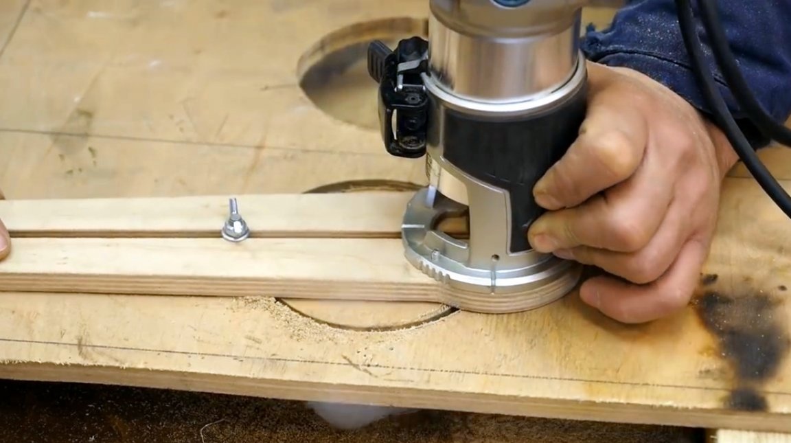
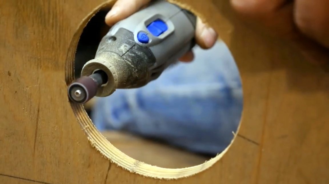
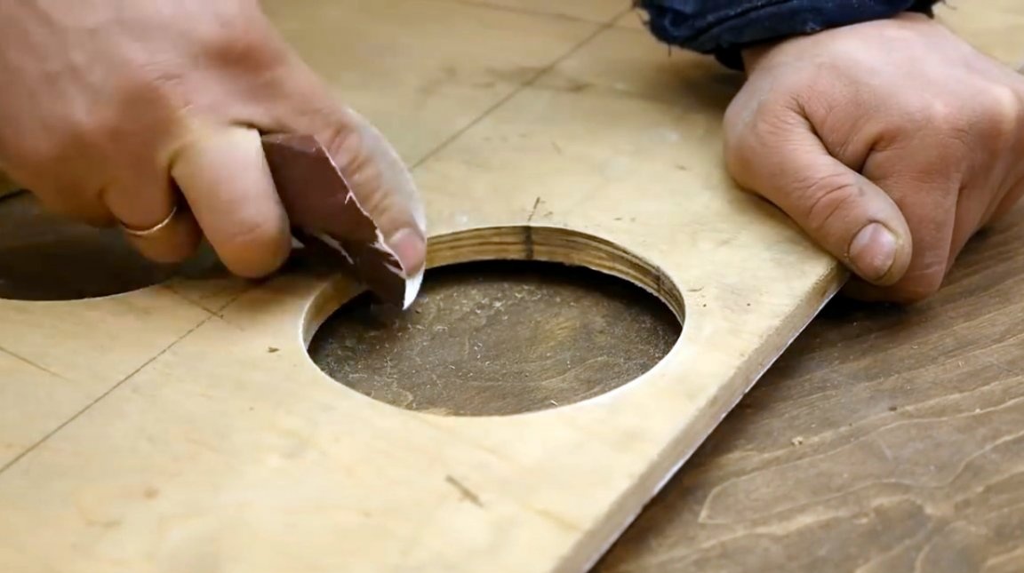
After milling, small chips and bumps remain at the edges of the plywood, he processes them with a dremel with a grinding nozzle, and then he manually overwrites the edges with fine sandpaper.

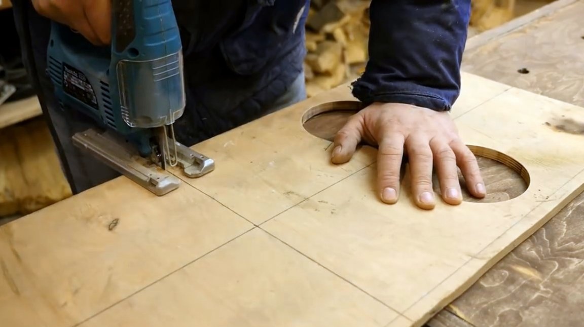
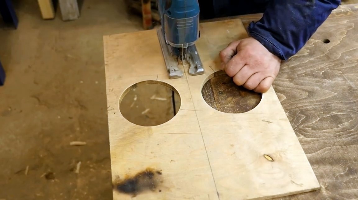
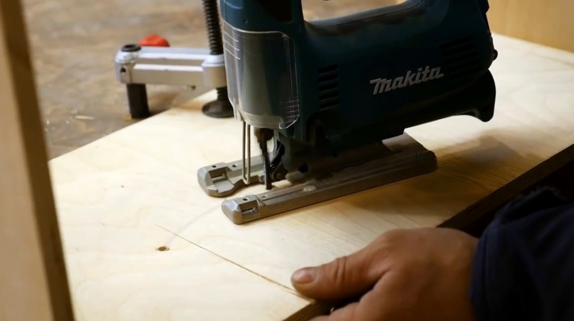
Now, with the help of an electric jigsaw, the workpieces are cut off from the sheet.
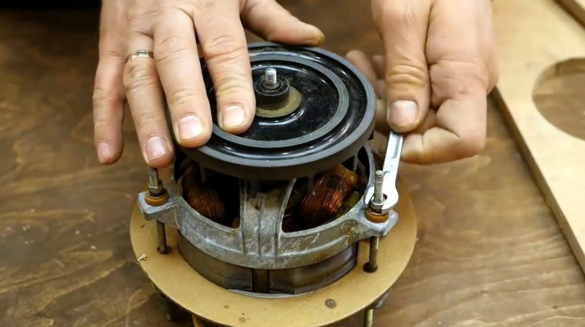
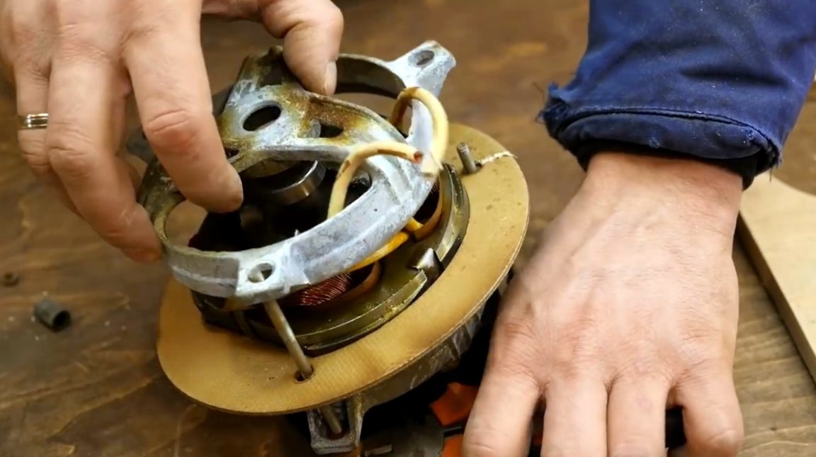
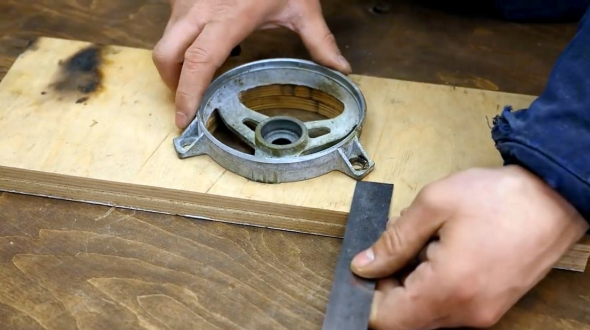
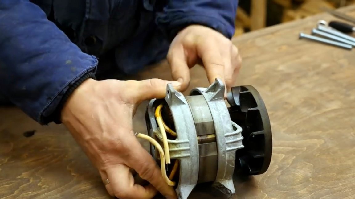
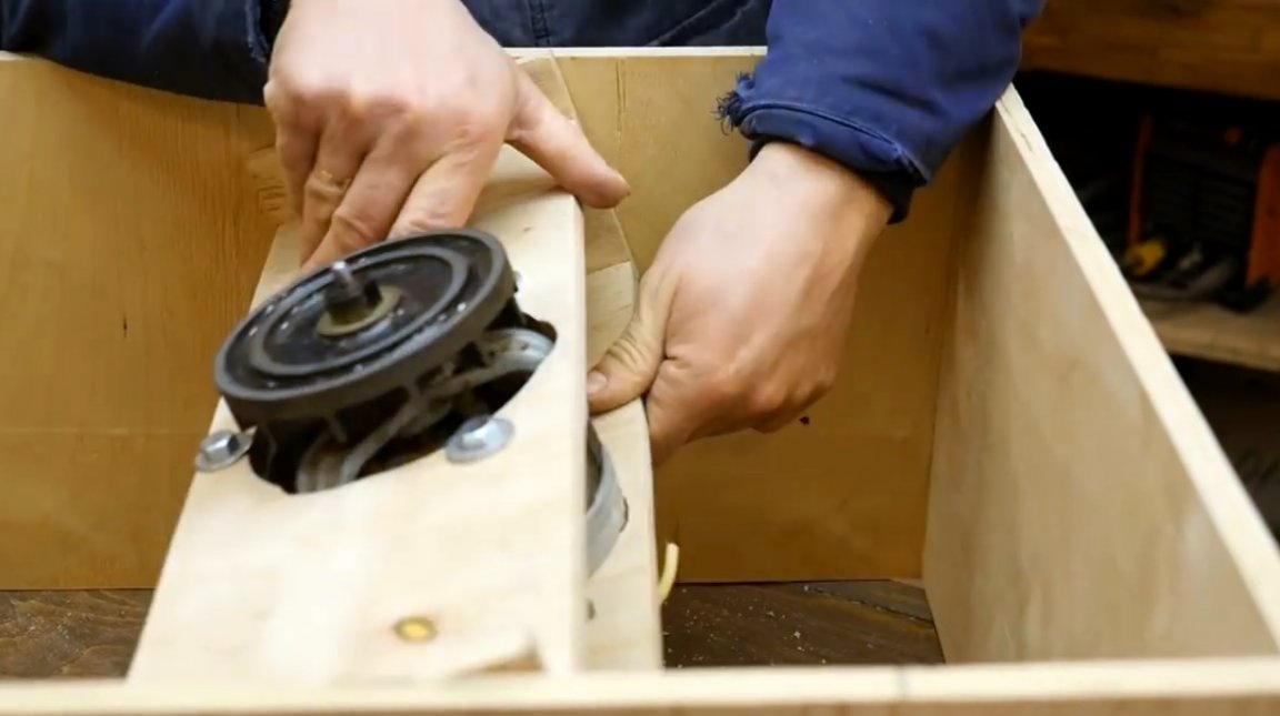
Next, you need to carefully disassemble the motor housing by unscrewing the nuts from the studs and removing one bearing shield. There is no need to remove the second one, and for this one would have to remove the cooling impeller.
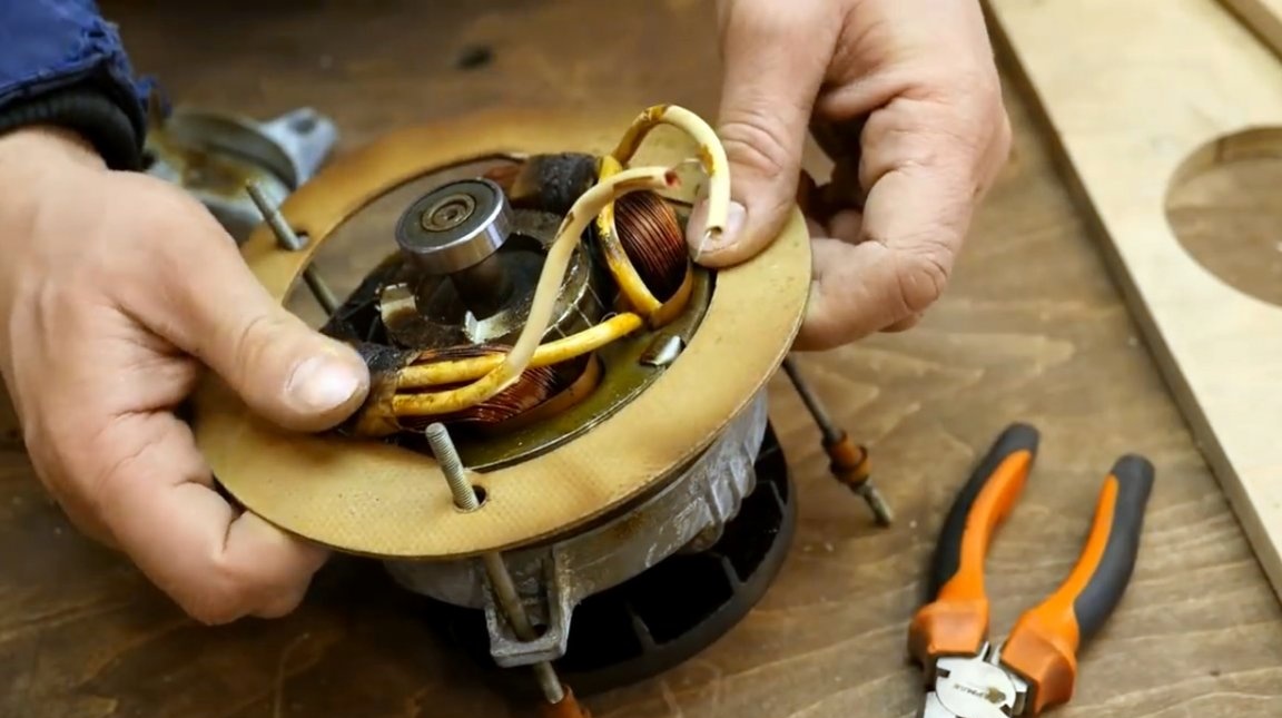
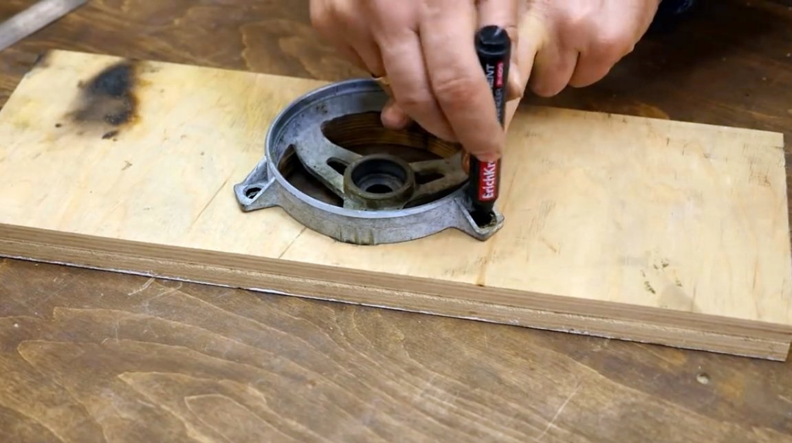
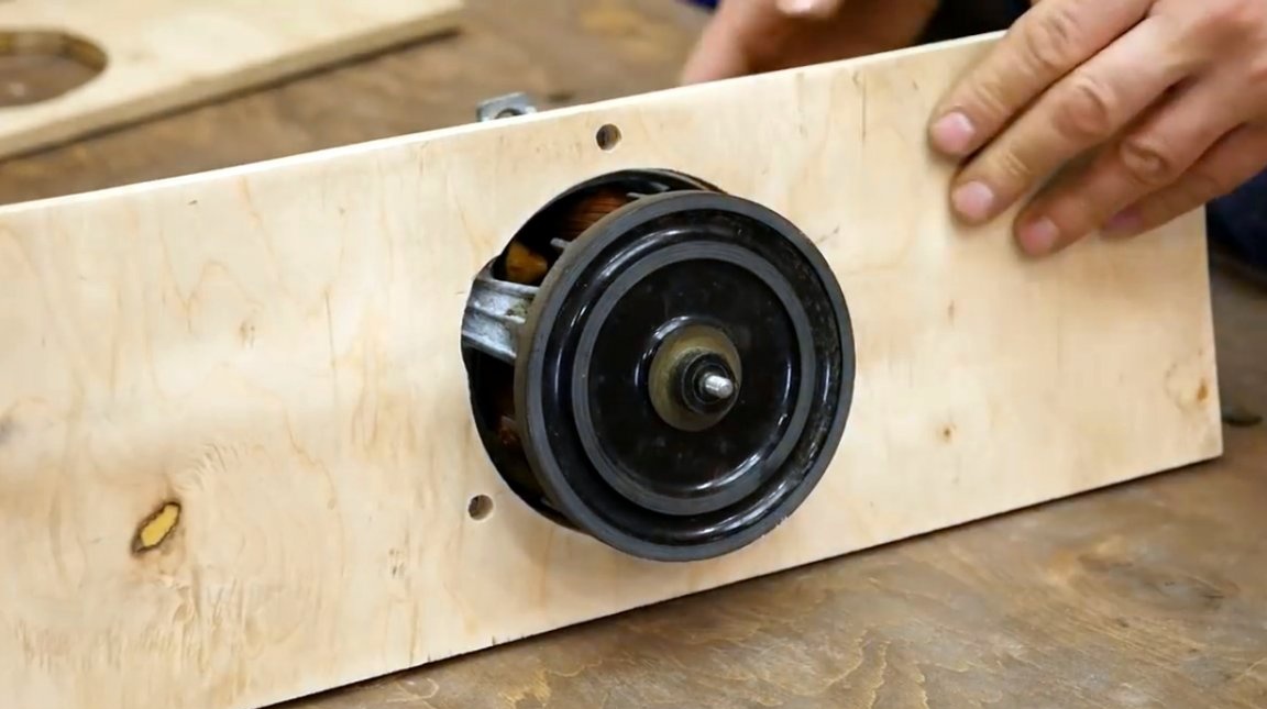
One of the bearing shields is installed in the holder blank (protruding ribs interfered a little, and small cuts had to be made for them), and holes for drilling are noted. The author does not have a drilling machine, therefore, to align the holes in both workpieces, he first drills one of them, then transfers the marks to the second. Then he checks the marks with holes in the shield, and repeats the drilling.
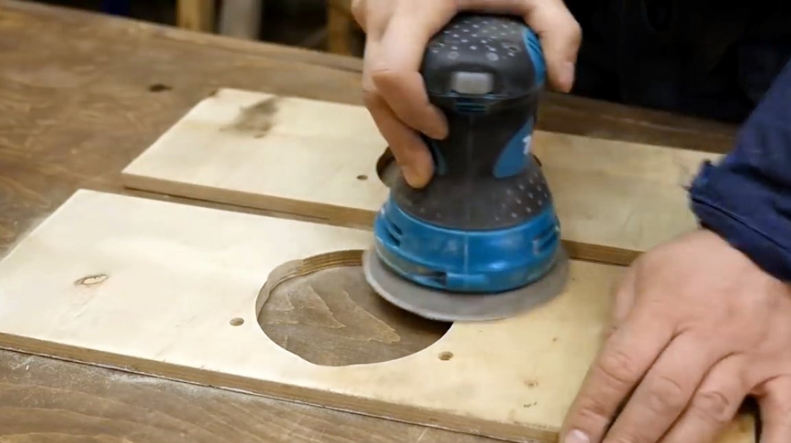
After drilling, all surfaces of the parts are ground with a manual orbital machine.
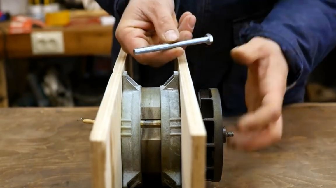
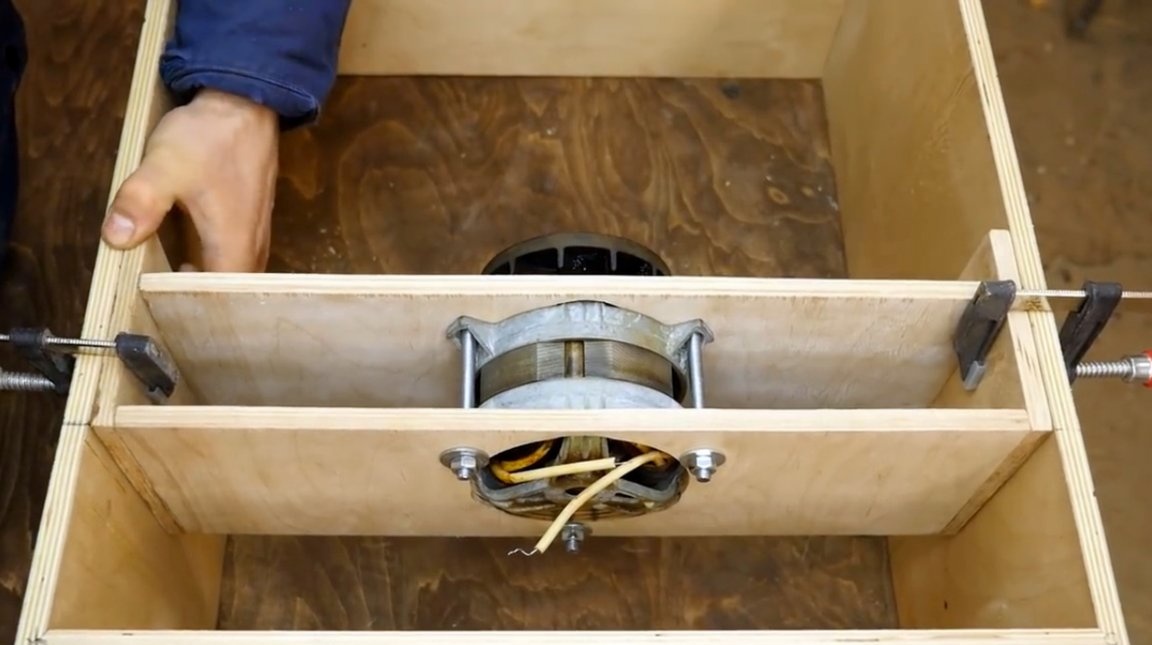
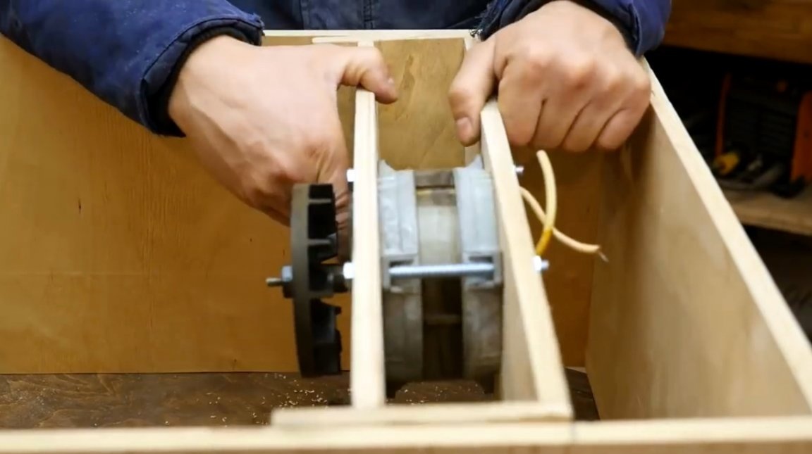
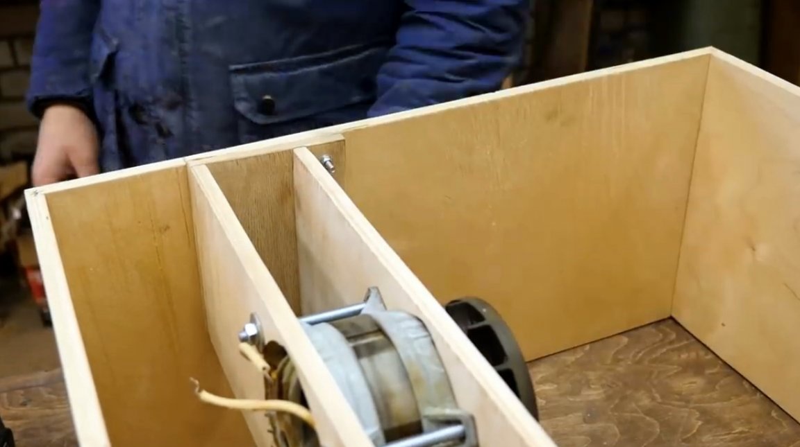
The bearing shield is installed in its place, coaxially with the second, and then installation of the engine in the holder begins.
The master had to replace the engine studs with long bolts. This was due to the fact that two layers of plywood (24 mm) were added, and the studs were short.
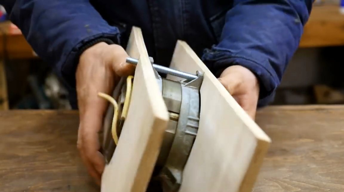
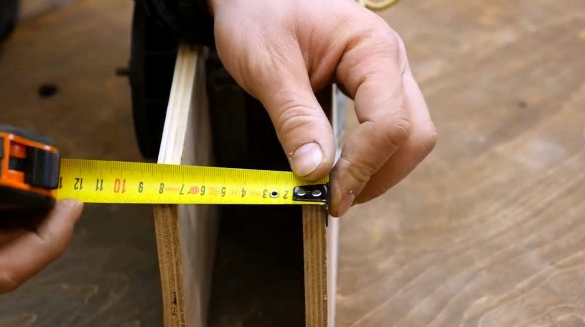
Having measured the width of the resulting holder (85 mm), the master makes two side walls, however they should be slightly longer (150 mm). The blanks are cut with a miter saw.
Holes for nuts and clamping screws are drilled in the side walls, which will fix the holder at a given angle.
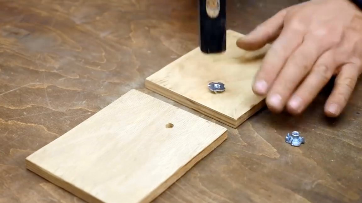
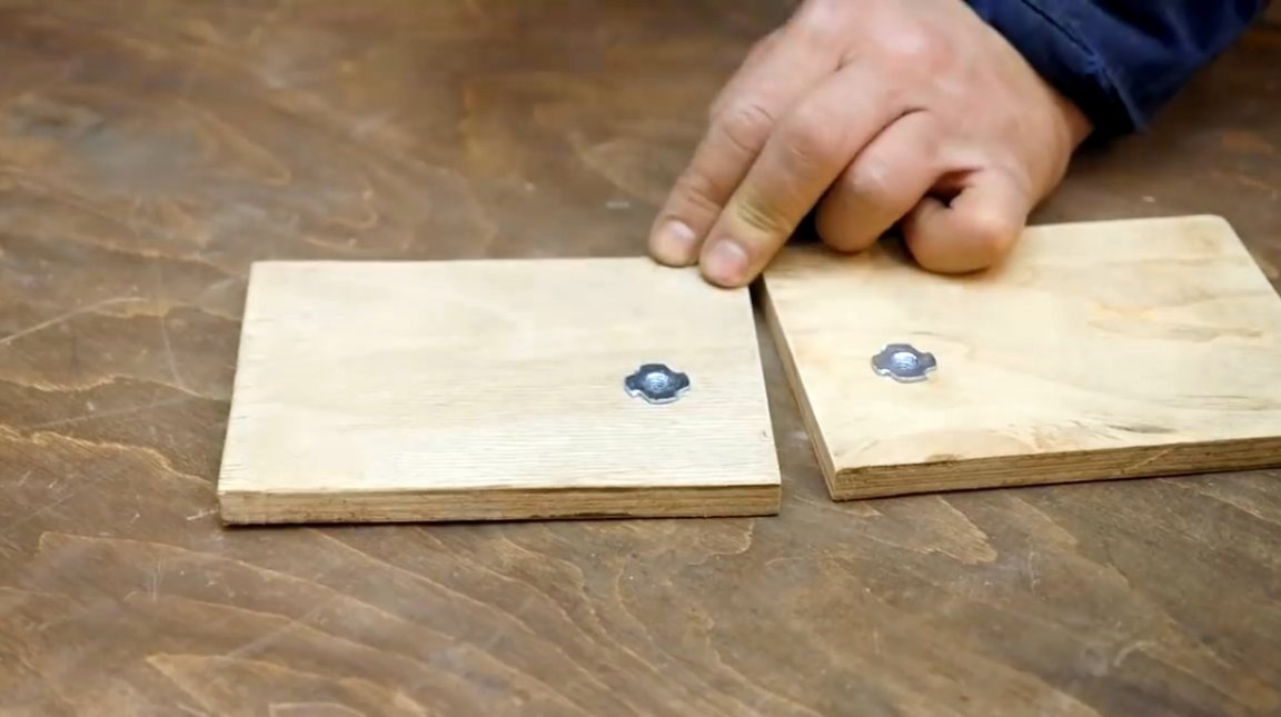
Now the master puts two furniture nuts in their place.
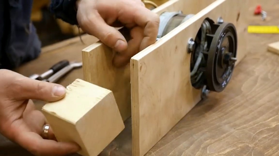
In order to adhere to the geometry of the holder, and to obtain a rectangular shape, the author inserts a block of a suitable size between the walls and checks using a square.
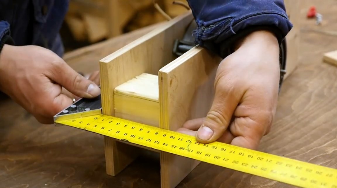
After that, the pilot holes are drilled with a countersink drill and the screws are twisted.
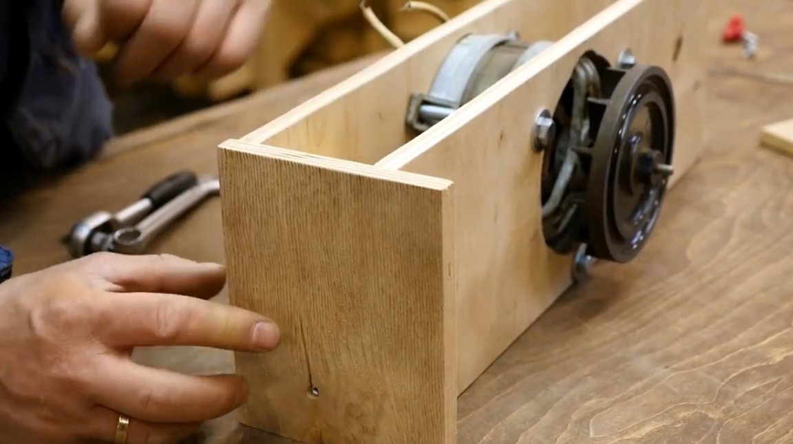

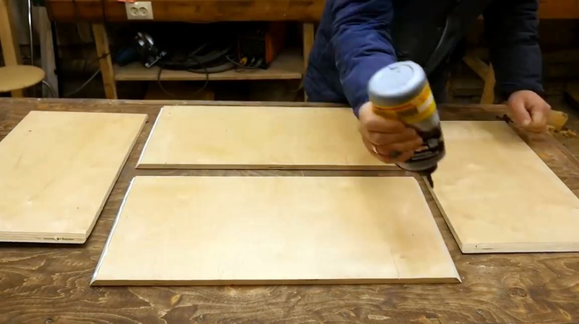
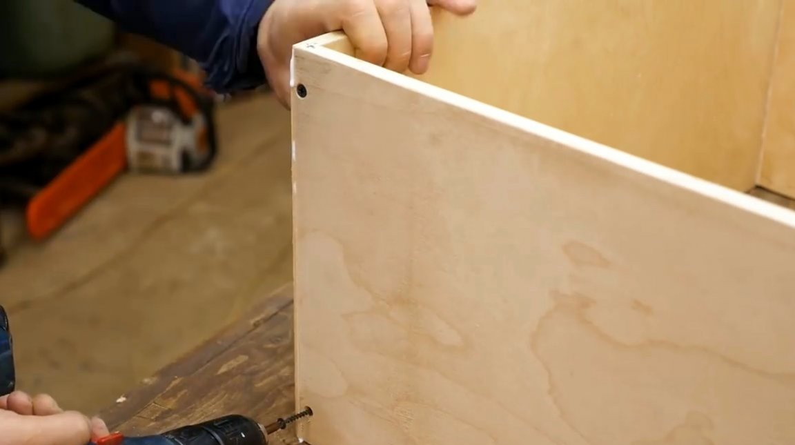
The next step is to make a housing for the machine. The author cut the blank for the lid and side walls, given the width of the module with the engine. He also cut some ends at an angle of 45 degrees. Drilling pilot holes, and lubricating the joints with glue, the walls of the body are fixed to each other with wood screws.

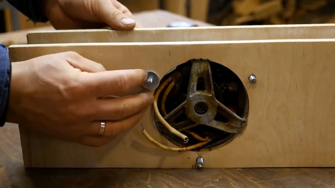
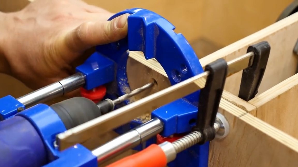
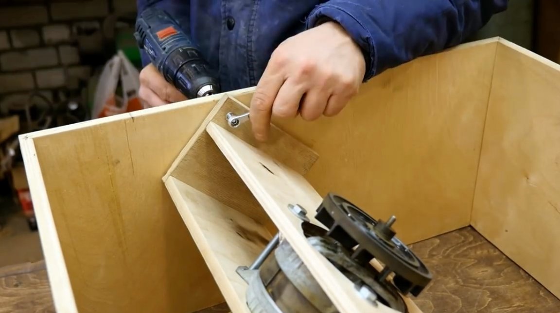
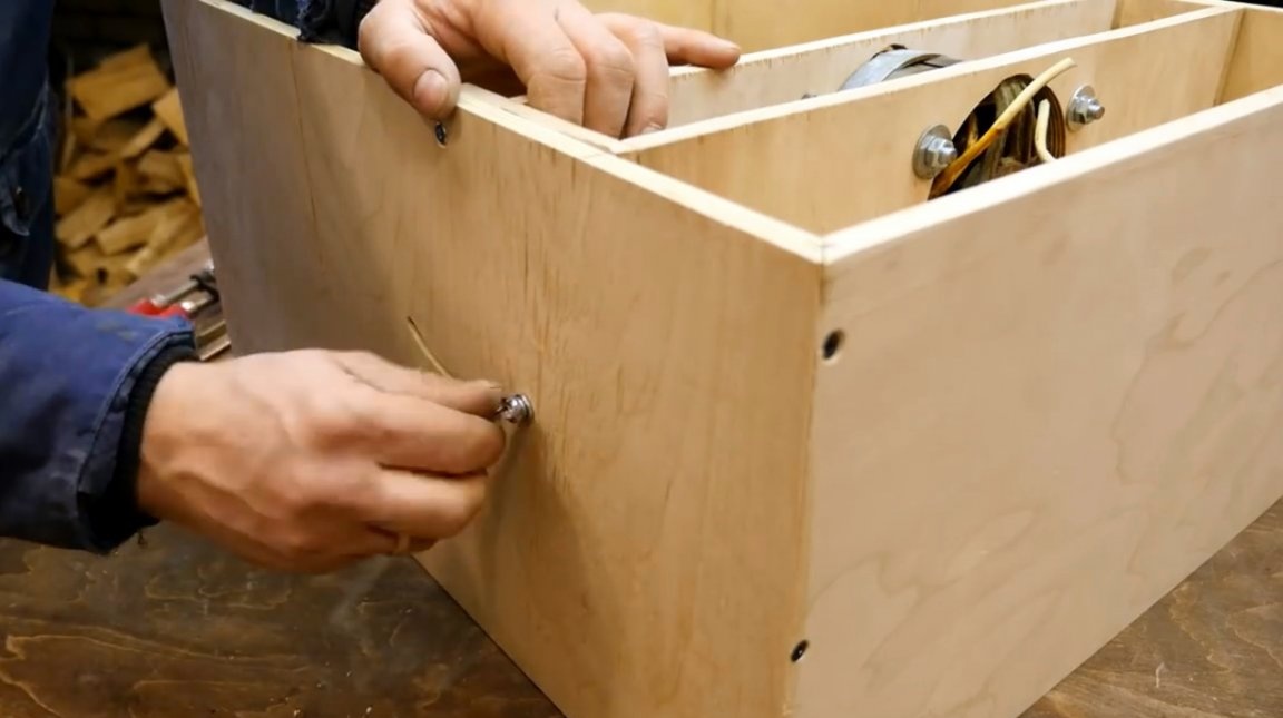
A module with an engine is installed inside the housing, and is fixed with two clamps. It is also important to observe a right angle. After that, drilling holes for axial bolts.
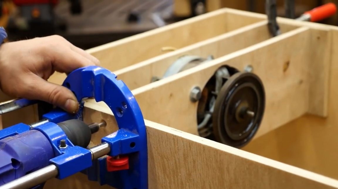
The master makes a preliminary assembly, fastens the movable block to the body with screws. Then he checks whether the module is freely tilted, and whether it clings to the walls of the housing.
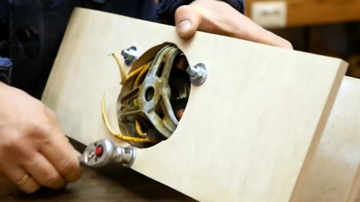
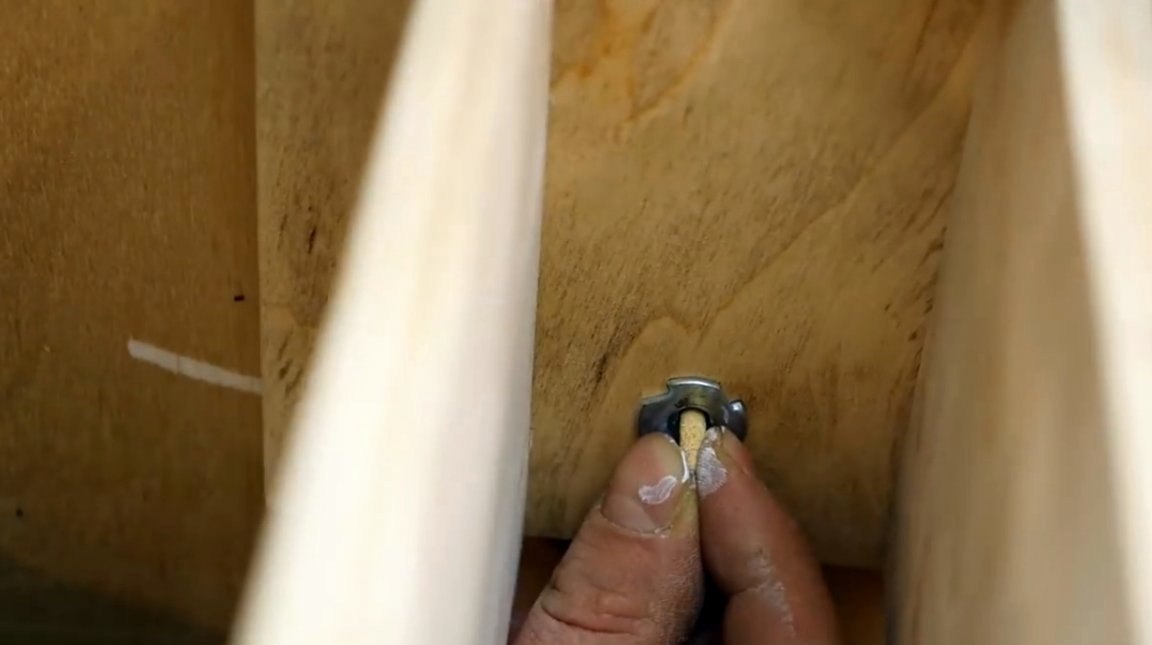
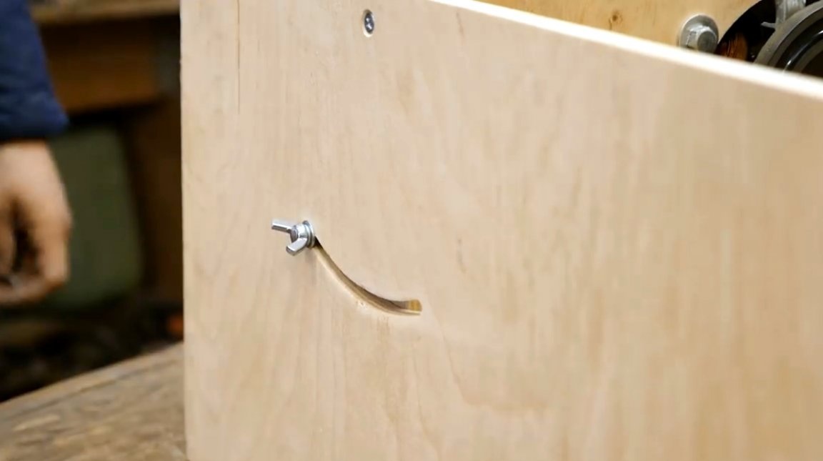
Now, in order to precisely make a slot for the clamping screws, the author inserts a piece of chalk in the center of the nut and tilts the central block.
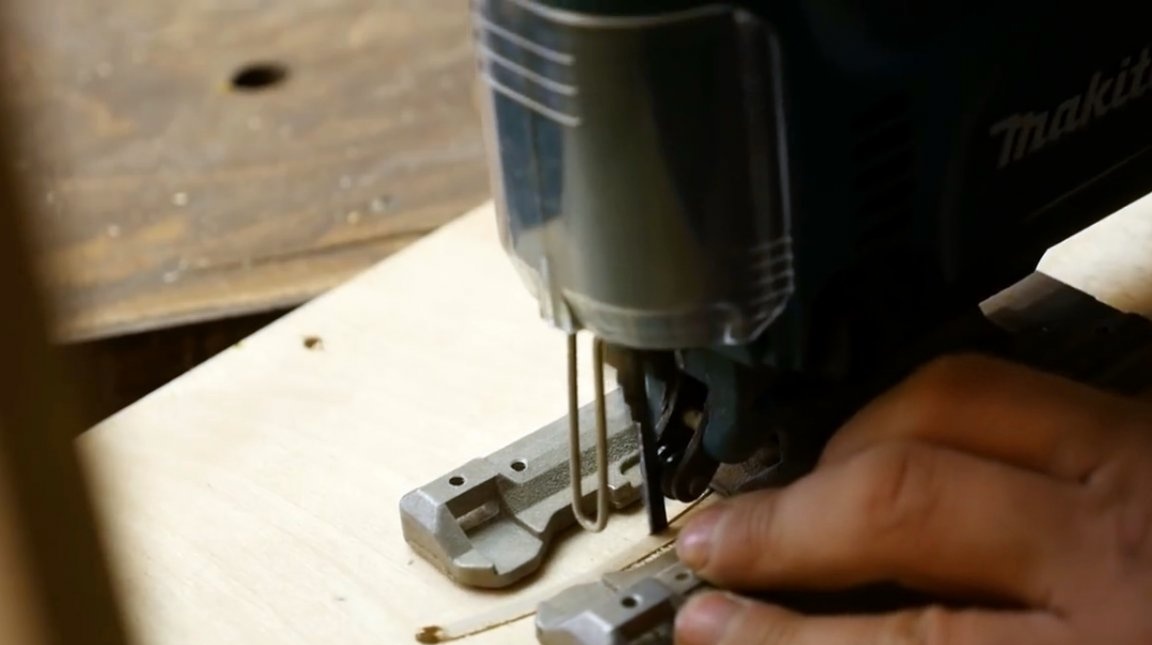
At the edges of the resulting arc, two holes are drilled for the entrance of the canvas. A cut is made along the two edges of the mark with a jigsaw.
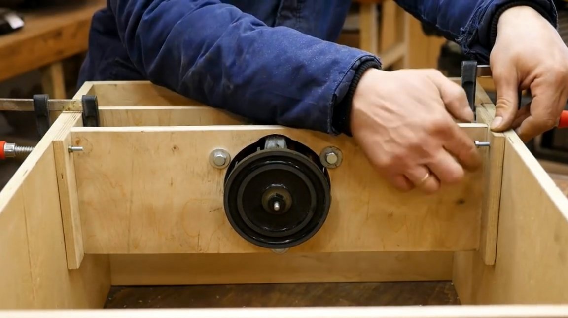
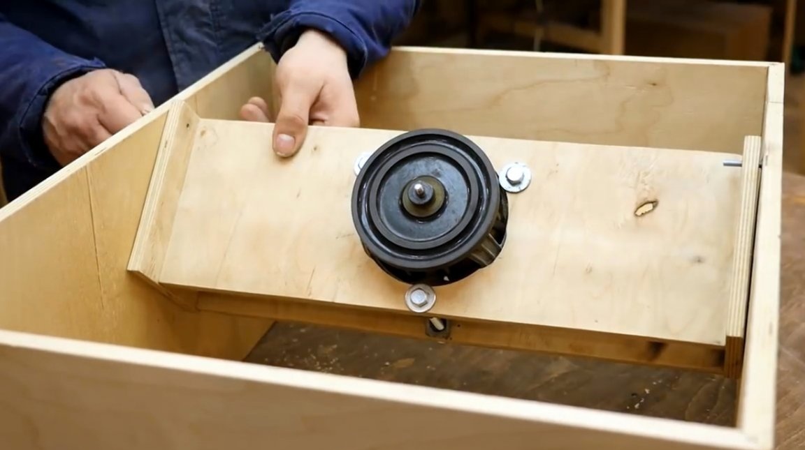
The central unit is finally fixed to the housing with axial screws.
Now the thumbscrew clamping screws are screwed in.
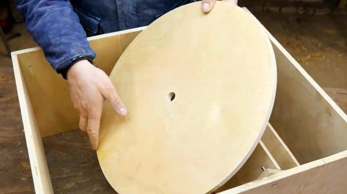
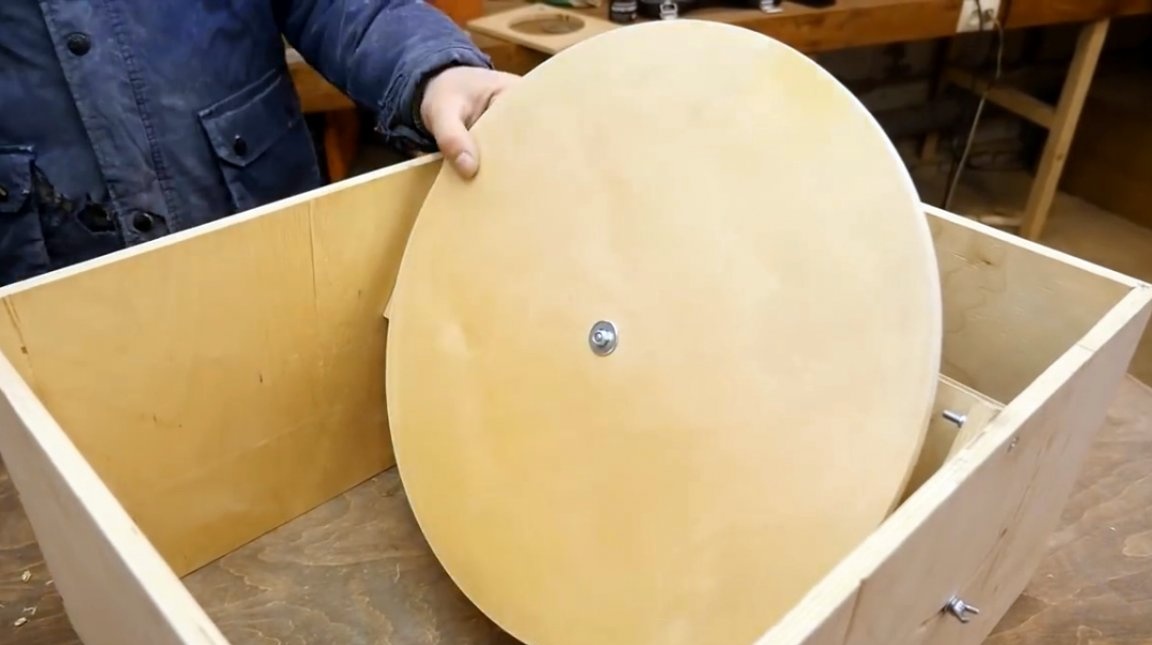
At the next stage, the master proceeds to manufacture the grinding disc. He marks the center on a square sheet of plywood 500X500 mm, and drills a hole with a diameter of 1 mm.
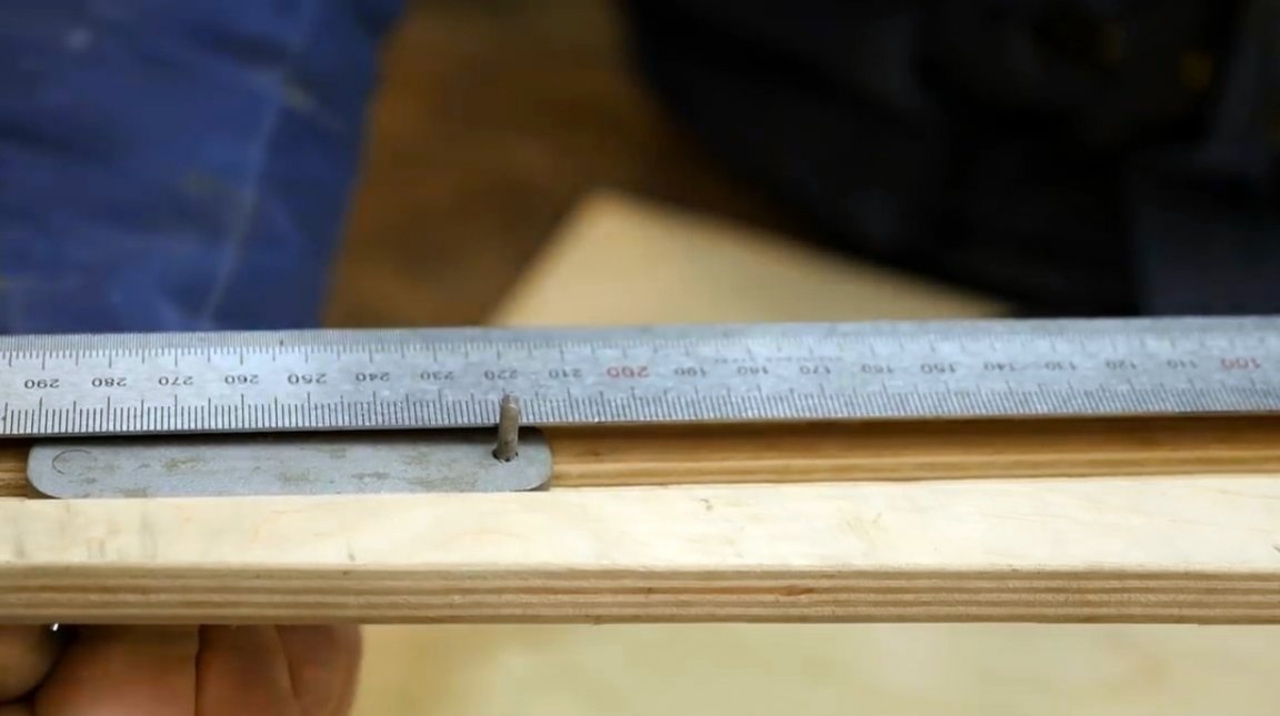
Having established a distance of 220 mm from the needle to the cutter on the circular nozzle, he cuts out a disk with a diameter of 440 mm. After that, all the edges of the disk are sanded with sandpaper, and its surface with an orbital machine.
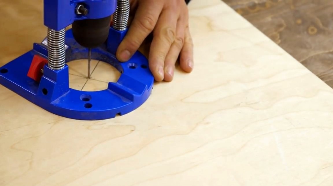
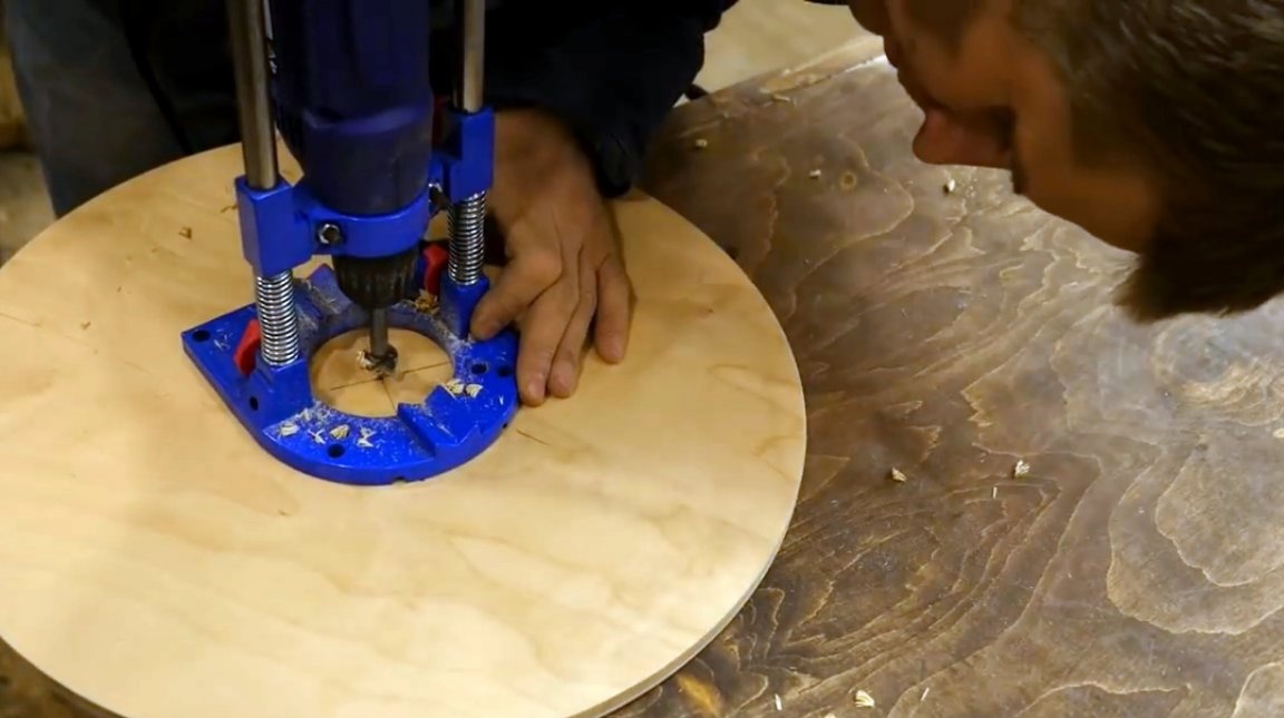
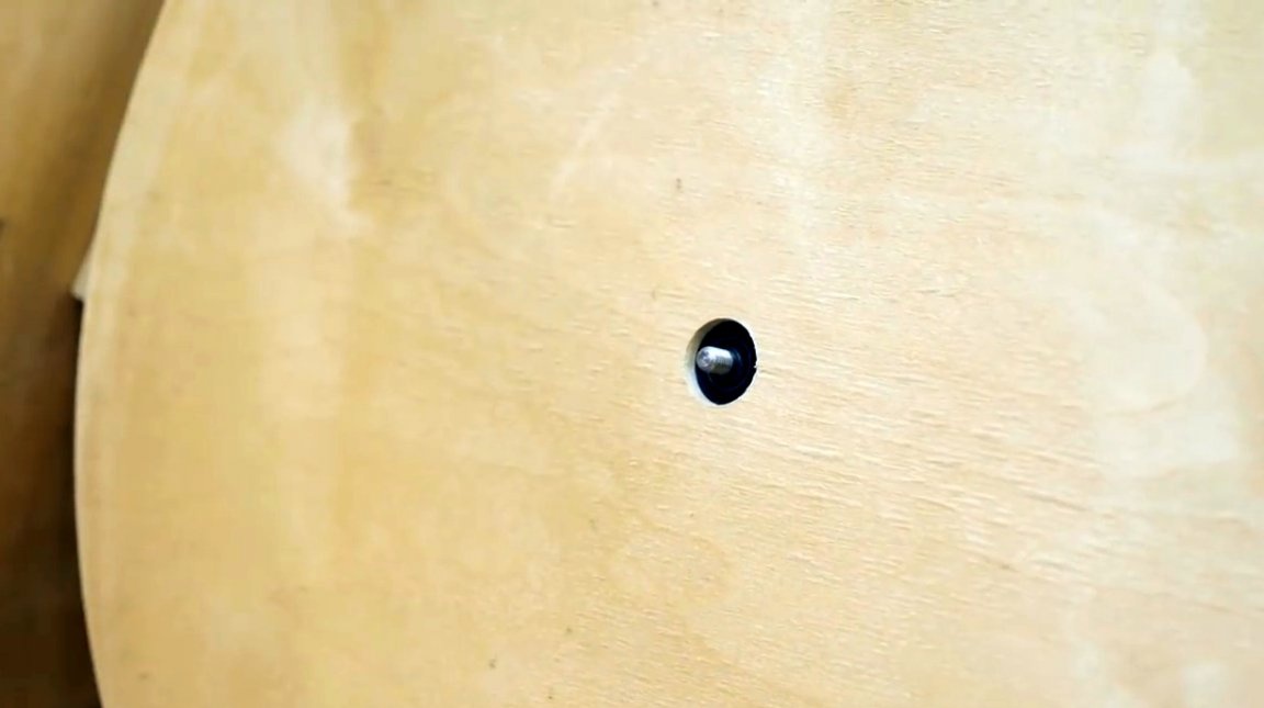
Using a guide for the drill, a hole is drilled in the center of the disc with a Forstner drill.
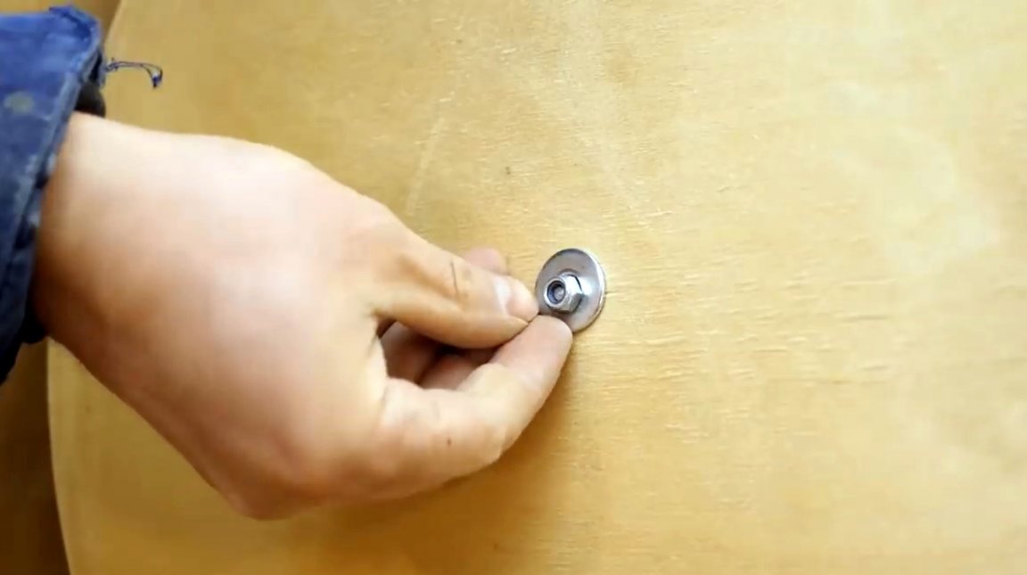
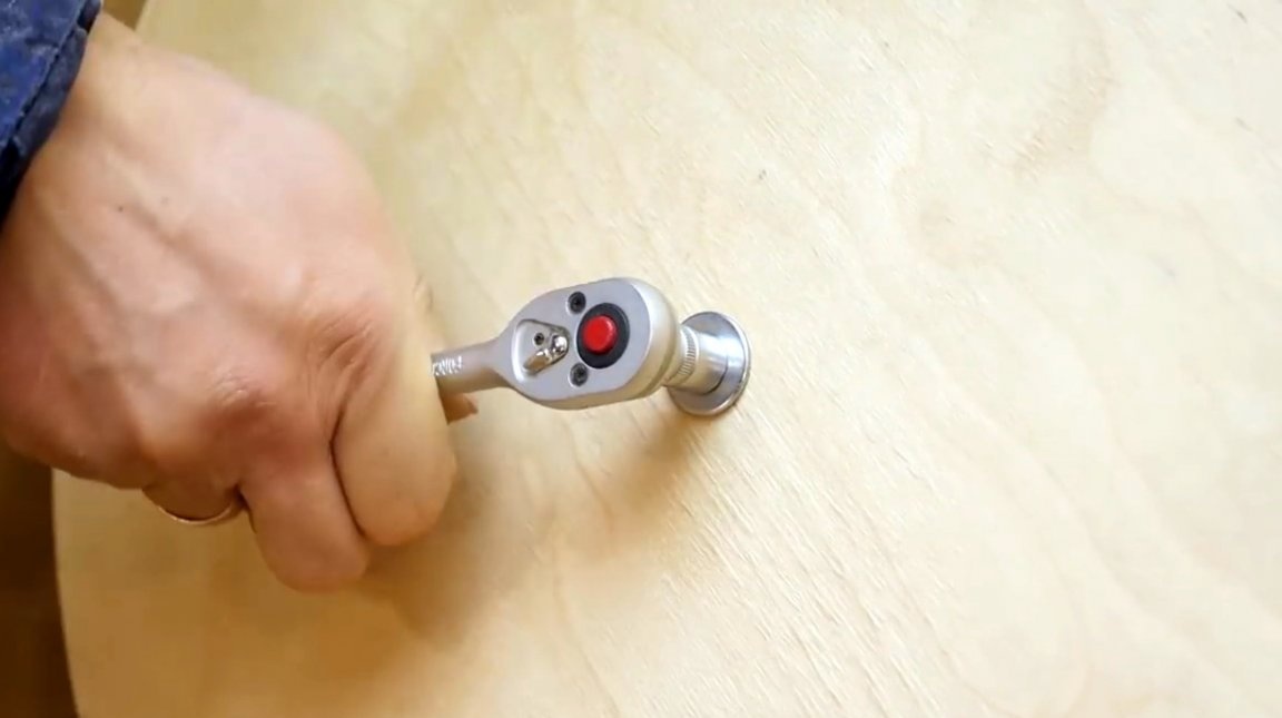
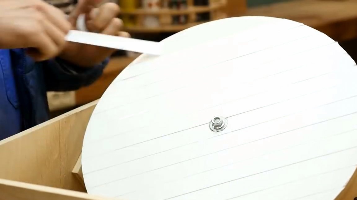
The disk is put on the motor shaft, and fixed on it with a nut and washer.
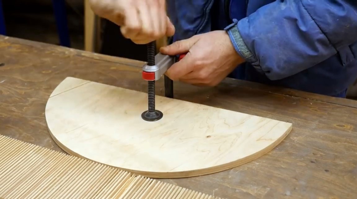
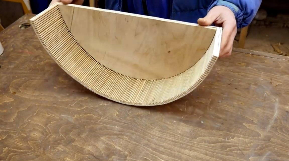
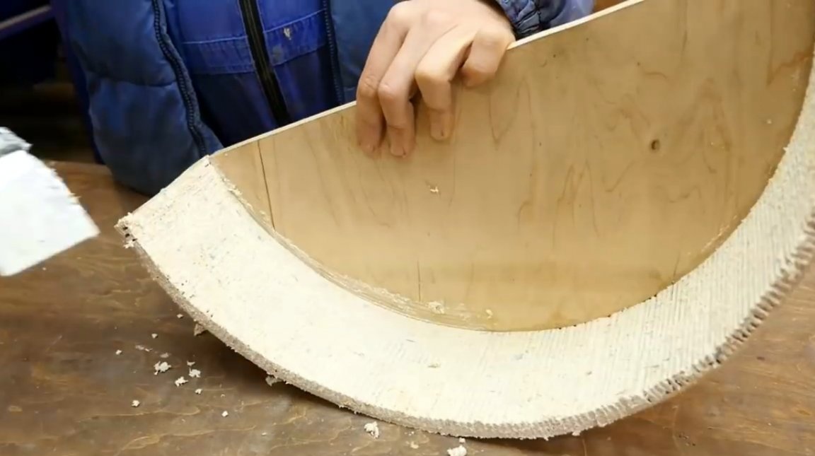
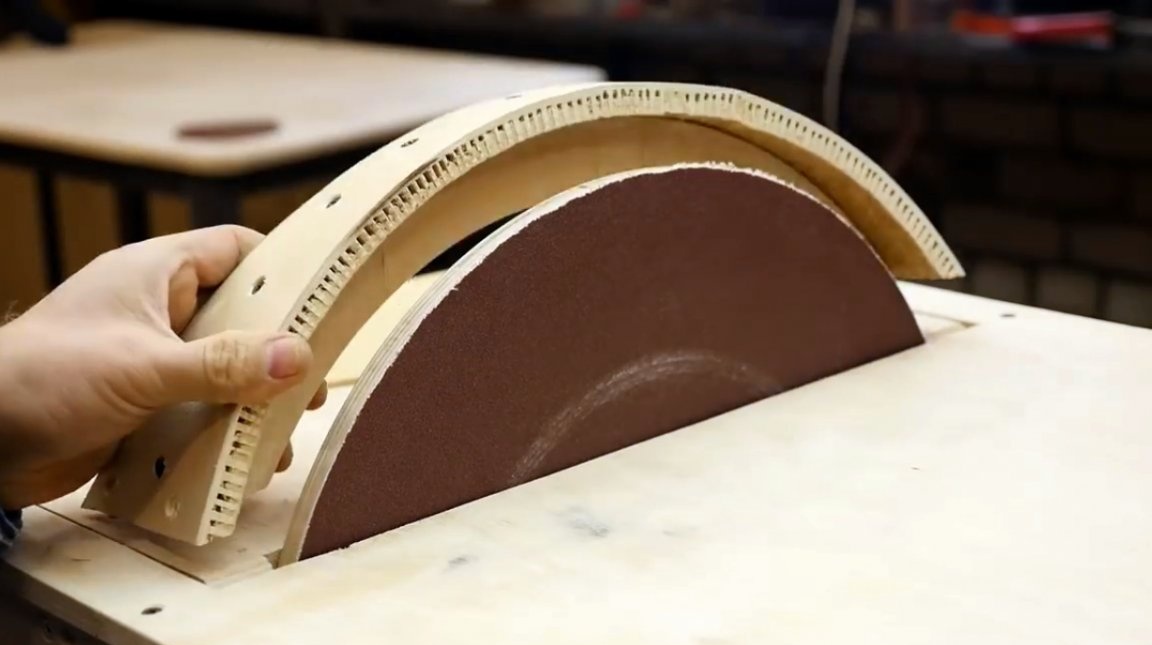
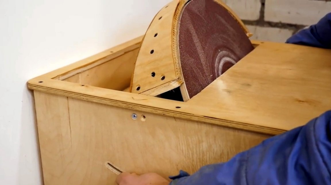
One of the last parts for the machine will be a protective cover. It can be made from sheet metal, however, the author decided to make it from plywood. In order to bend it, he uses a fairly simple technique.
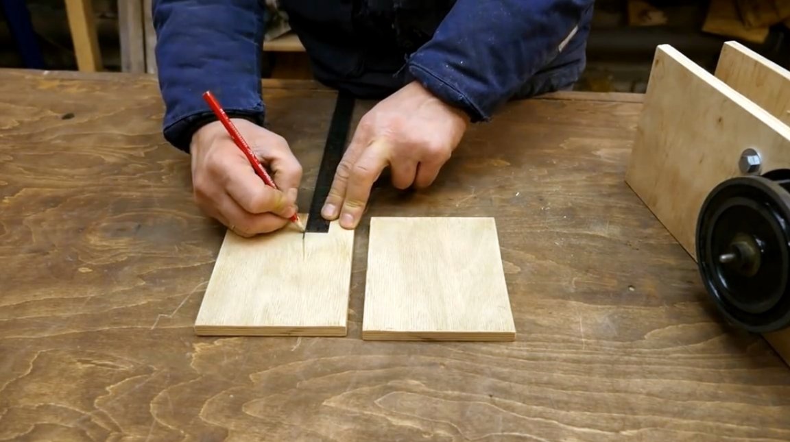
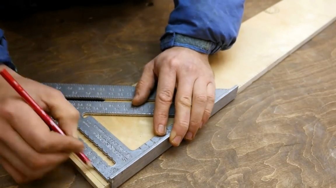
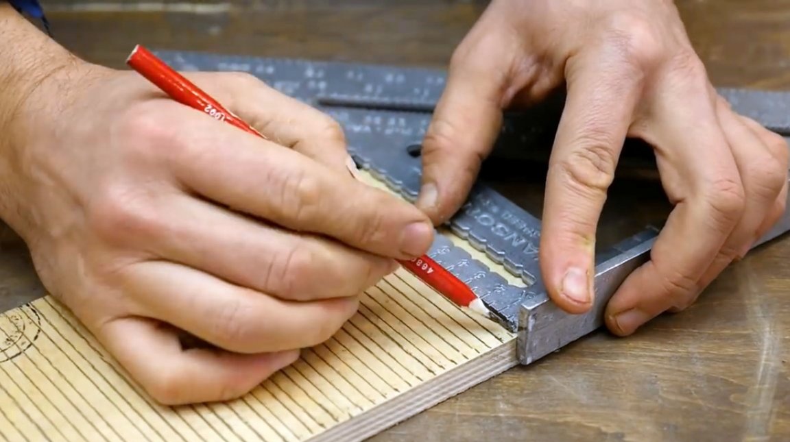
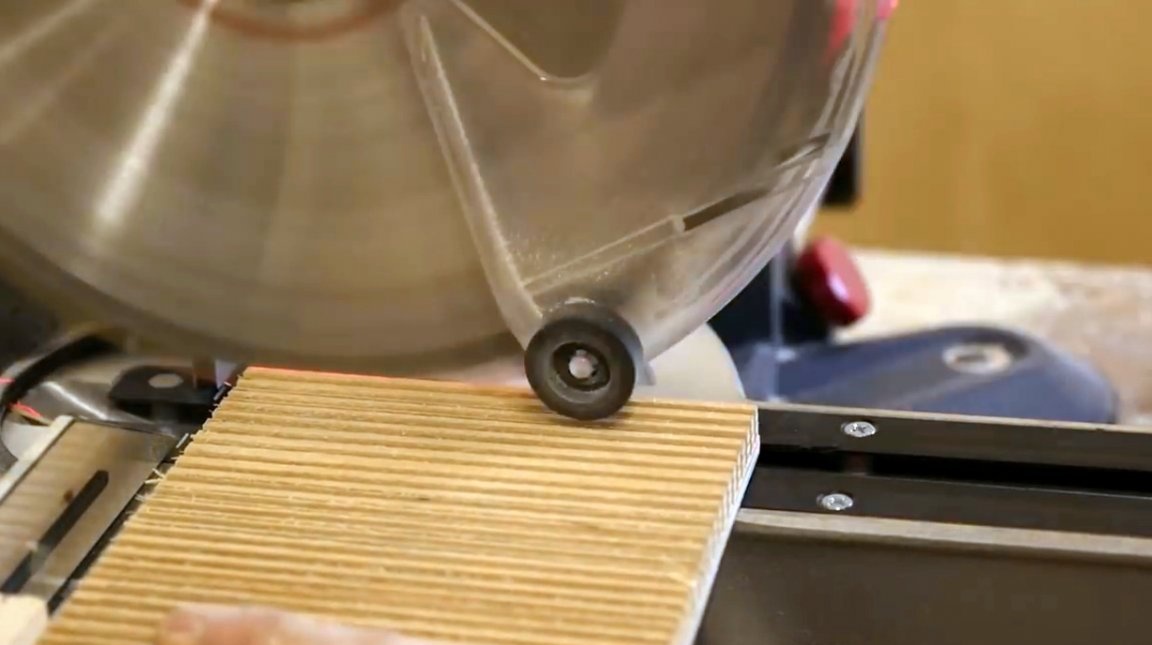
First, markings are applied to the plywood blank with a pitch of about 8 mm.
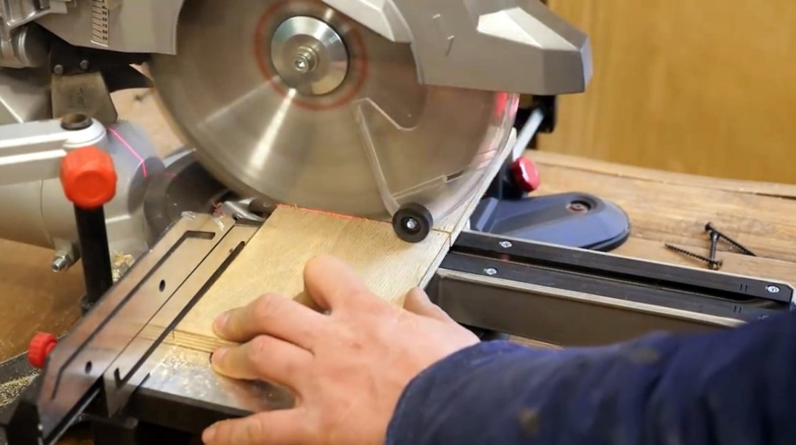
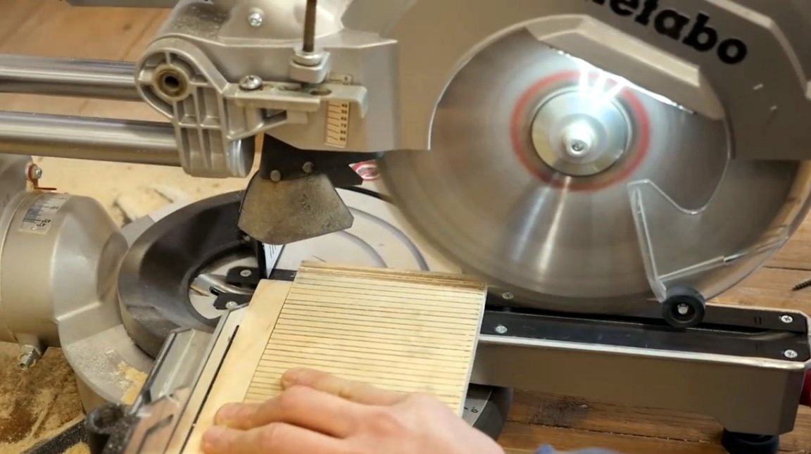
Further, a series of cuts for marking is made on the miter saw, their depth should be such that the saw blade does not cut through the last layer of plywood. A special limiter is used for this.
The author also prepared a back cover for the casing.
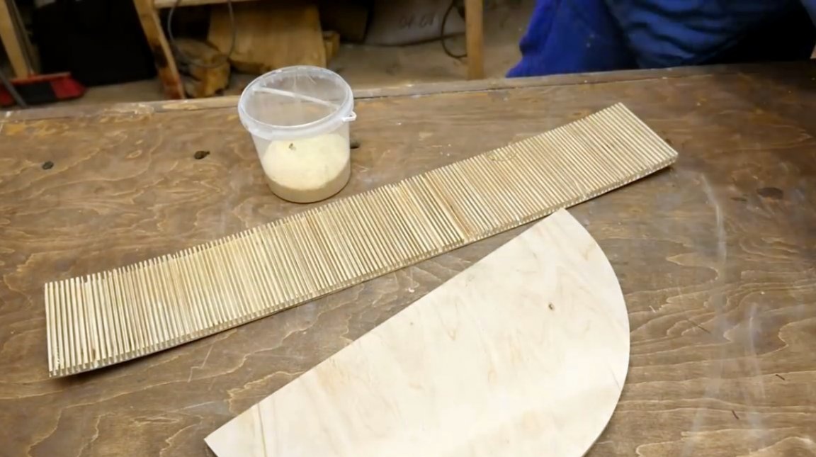
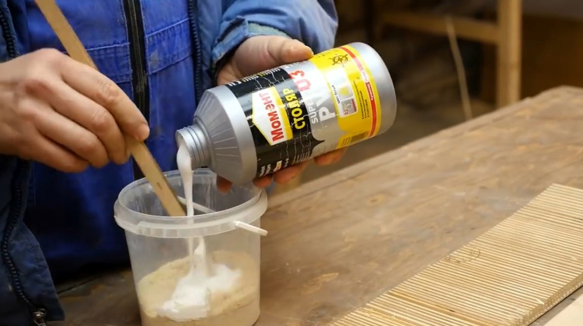
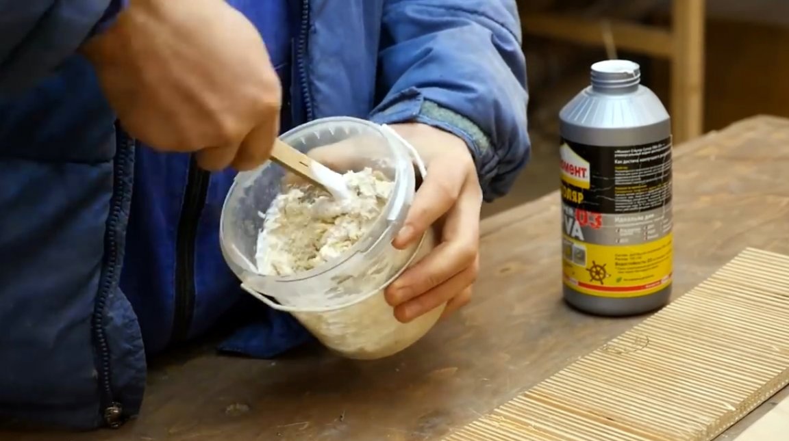
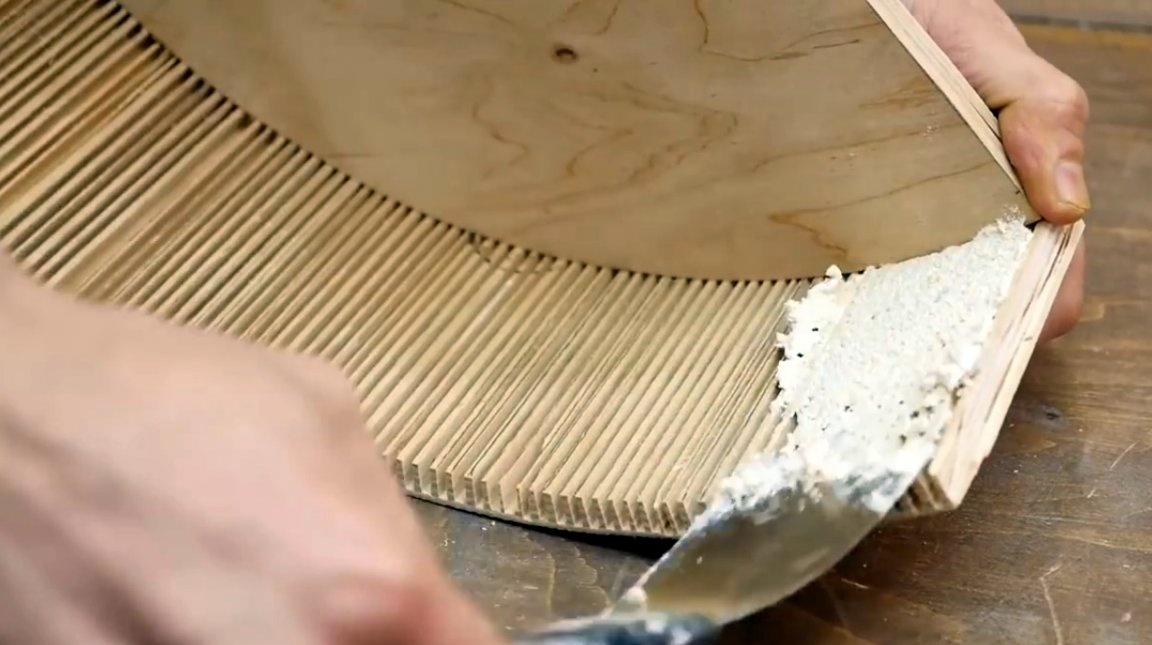
As a putty, he will use a mixture of fine sawdust and PVA glue.
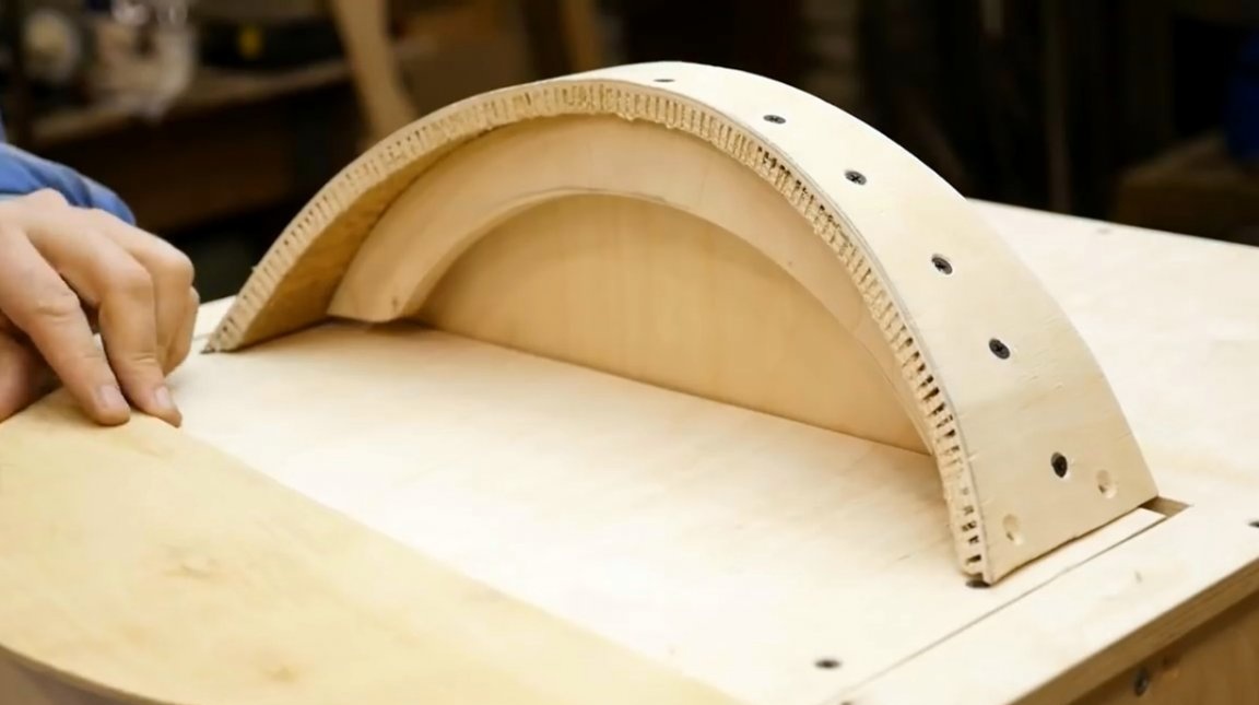
The lid is fixed on a workbench, and a plywood blank is screwed to it at several points, forming an arc.
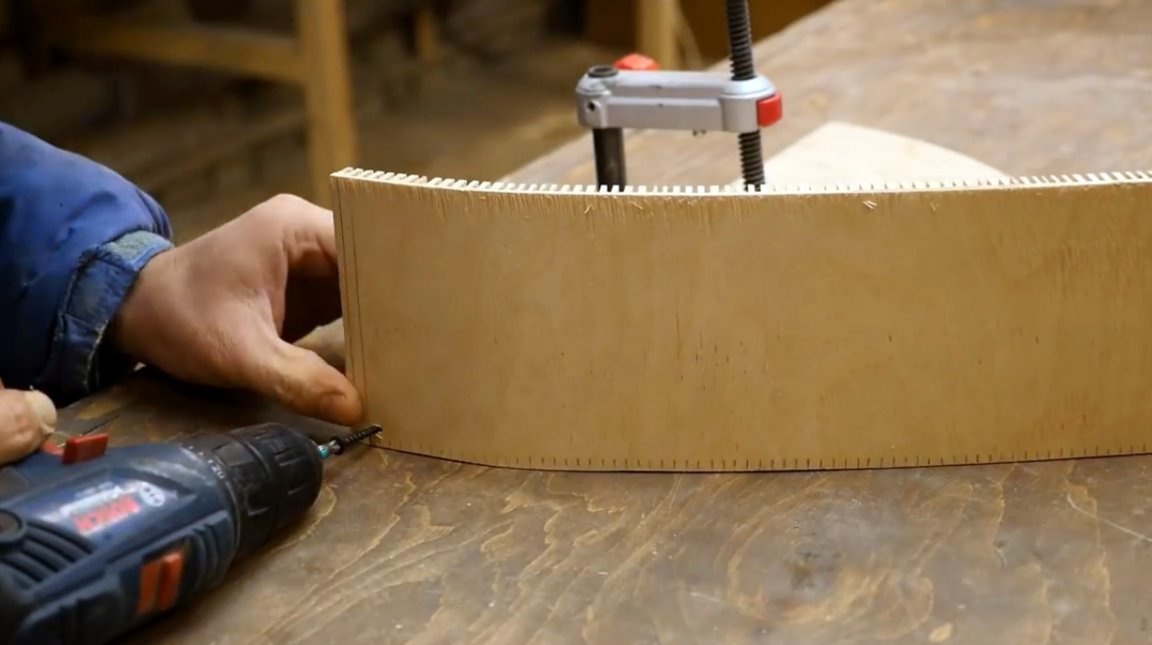
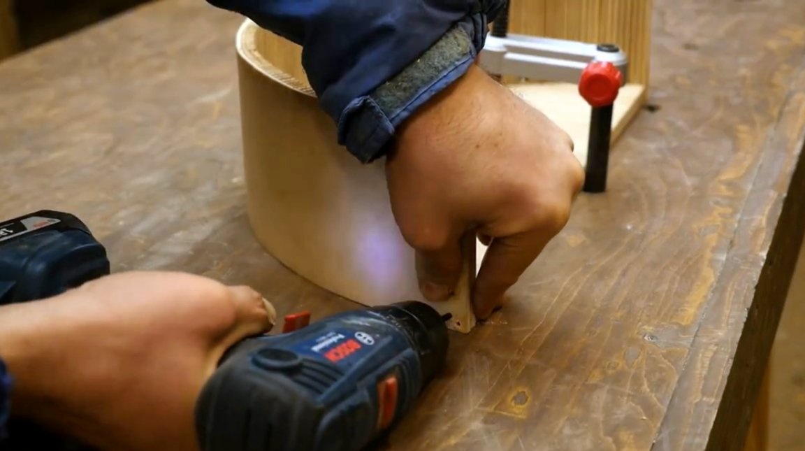
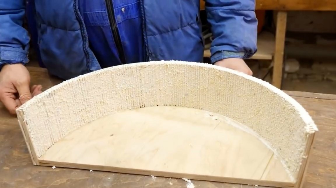
It remains only to densely fill all the slots with a prepared adhesive mass, and leave to dry.
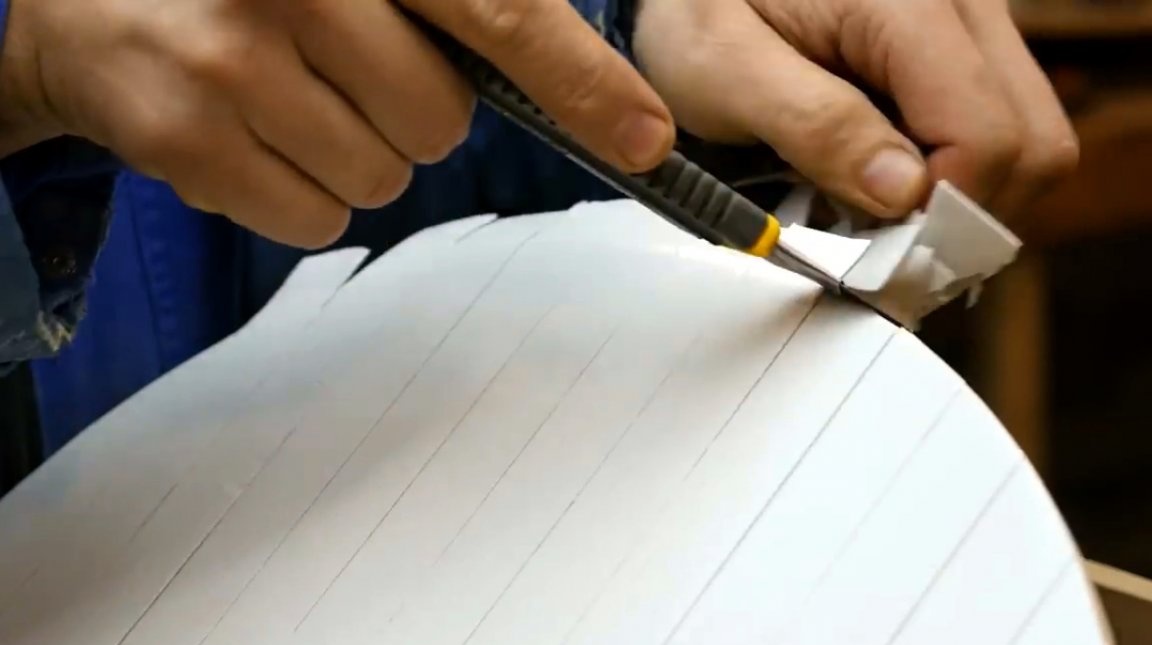
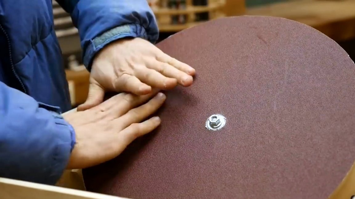
The author sticks strips of double-sided tape on the surface of the disc. Although to quickly replace sandpaper, you could use the usual "Velcro".
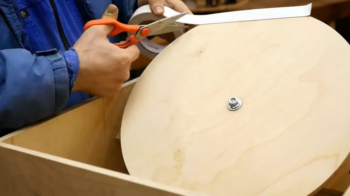
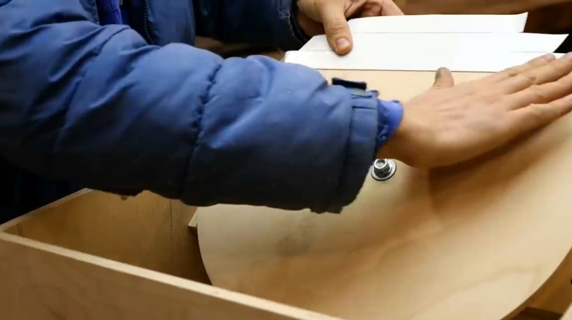
Excess tape is cut around the perimeter with a knife, and a protective tape is removed from it.
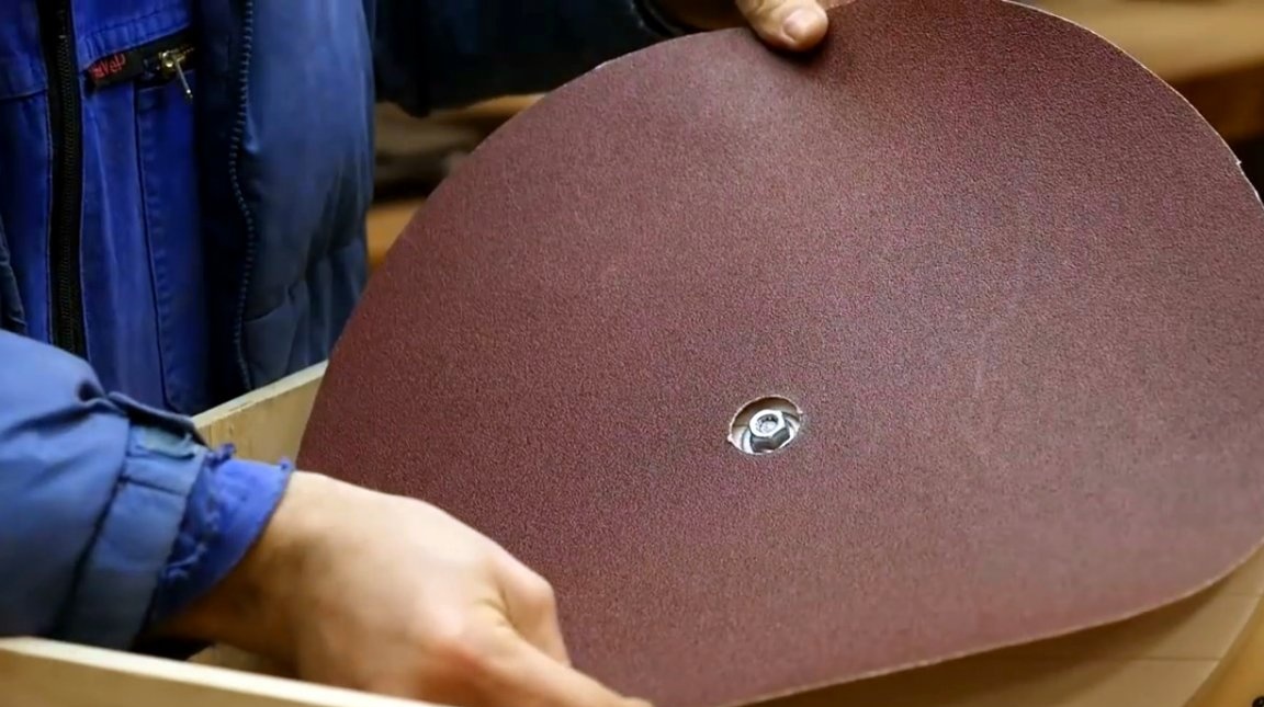
Now you can stick the sandpaper disc in place.
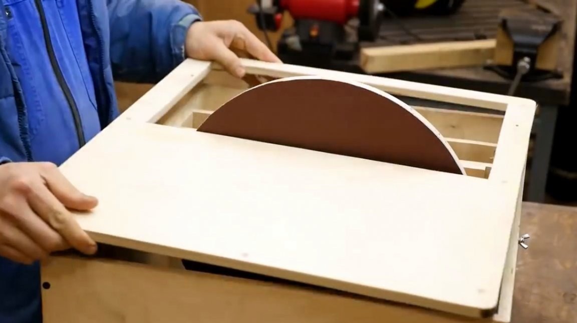
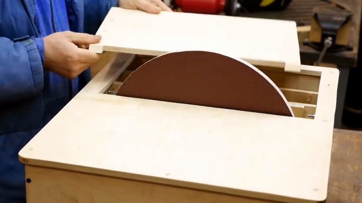
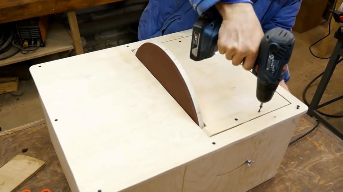
The author prepared two parts for the table, and screwed one of them to the body, and the second to the inclined block.
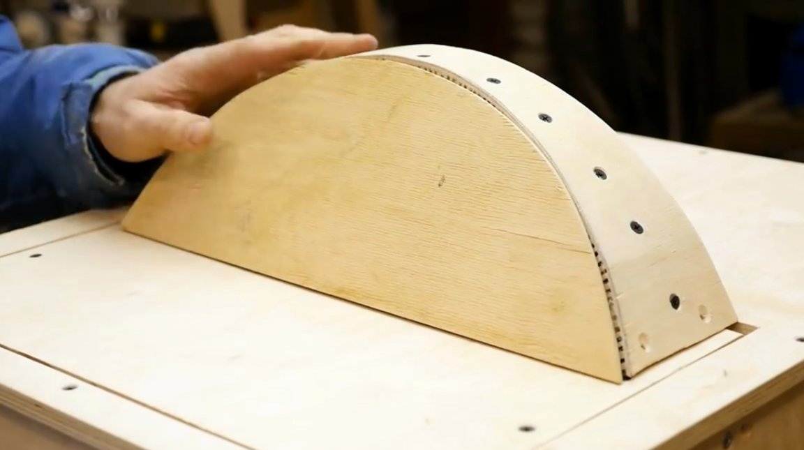
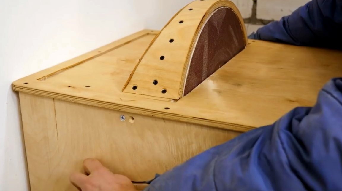
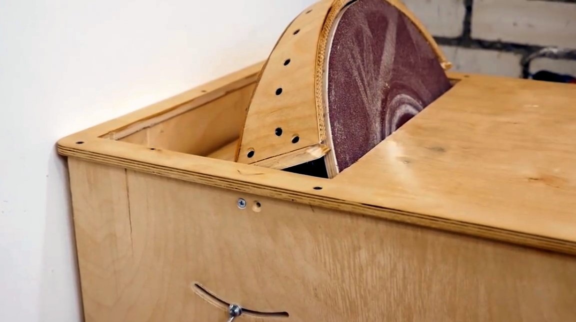
The protective cover was slightly modified and reinforced by an arc of plywood. Also, the author cut his back at a slight angle.
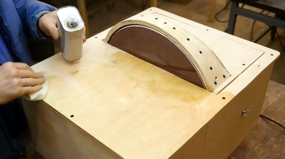
To protect the case from moisture, all wooden surfaces are treated with wood impregnation, you can also use wood varnish.
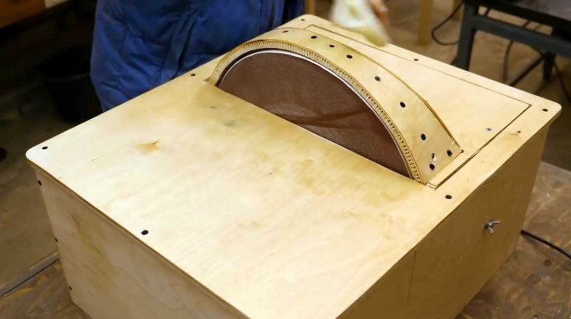
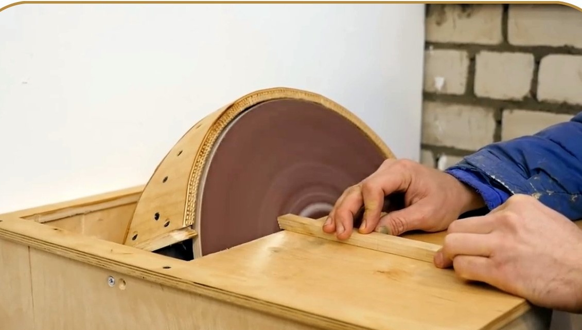
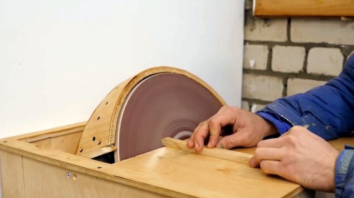
So, the machine is ready, you can begin to test it.
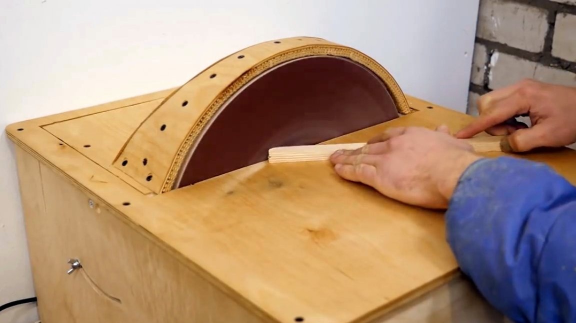
Now the author tilts the disk relative to the table, and fixes it in the desired position. The maximum angle of inclination is 45 degrees.
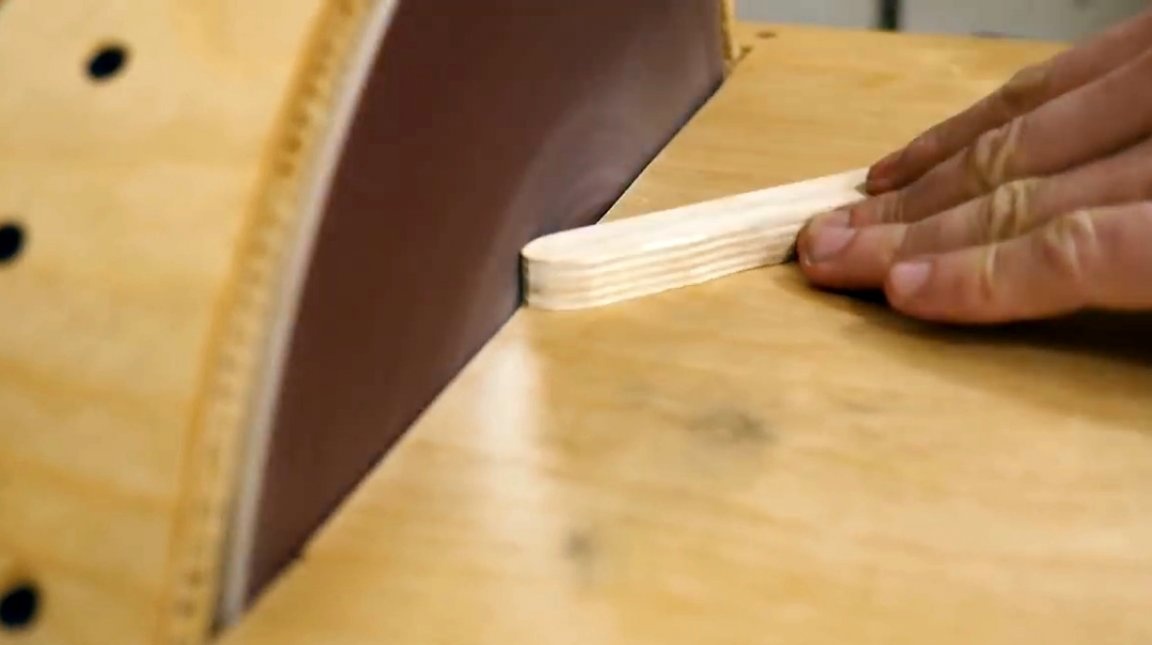
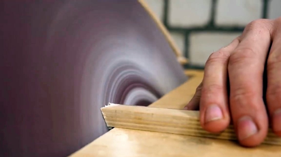
In this way, you can not only grind workpieces at the right angle, but also sharpen knives or carpentry tools.
I thank the author for the simple design of a very useful workshop machine!
All good mood, good luck, and interesting ideas!
Author video can be found here.