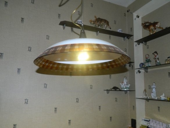
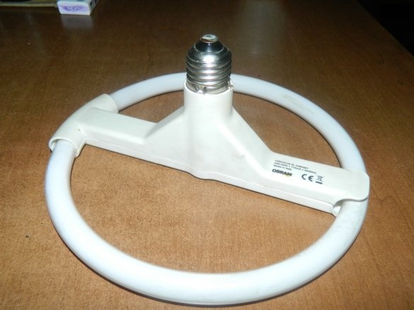
I have a lamp hanging over the kitchen table with a bagel-type energy saver: power - 24 W, lampholder - E27.
As the manufacturer (respected OSRAM company) assured, it will last at least 15,000 hours, but burned out after 1.5 years. I put the last spare. But, since these lamps cost decently (somewhere around 500 rubles - you won’t save enough money), I began to think how to make an LED lamp that can replace this one (now I have ring radiator plates for emitter type LEDs, then I don’t It was). And then I remembered an article where the author remakes energy-saving E27 lamps, using only a housing with a base from them.
Having found this issue in the binder of magazines, I began to study the material and made the following conclusion: the light bulb described at the end of the article will not work long and will "die" from degradation due to overheating.
LEDs have the highest efficiency of all radiation sources. The best LEDs have almost 50%. (For comparison: incandescent lamps - 5-8%, halogens - 10-15%, energy saving - up to 25-30%. Therefore, powerful LEDs are very hot and do not tolerate overheating - degradation begins, i.e. the light flux decreases when the LED works at elevated transition temperatures (and the maximum transition temperature is 60 ° C). Roughly speaking, at each watt of a powerful LED one watt of thermal energy is released, and it must be taken somewhere, otherwise ...
In the article, the author solders high-power LEDs directly onto a board made of foil-coated fiberglass, without thinking about heat dissipation, without using hot-melt adhesive or thermal paste, and even more so - a radiator. On the other hand, there are boards assembled according to a power supply circuit with a current-limiting resistor. It does not add anything good to the overall temperature balance. therefore must use a radiator for cooling for powerful LEDs! (Have you noticed that I'm talking only about powerful LEDs?).
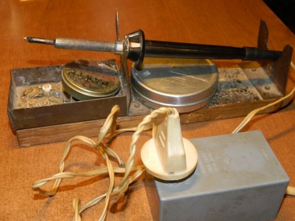
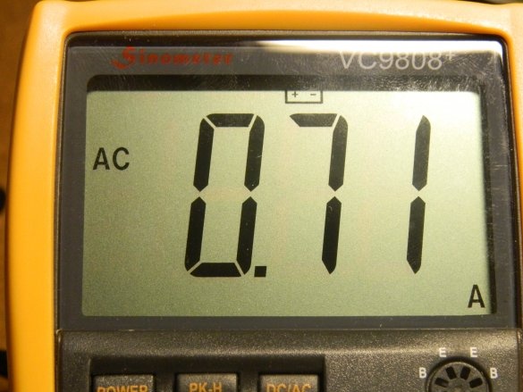
The author uses capacitance for high-power LEDs in power circuits, which negatively affects energy savings. For example, a 25-W low-voltage soldering iron is fed through a block from the mains, after disassembling which we will see a 10 μF x 400 V film capacitor. However, by measuring the current consumed by it from the mains, we will see that it is 0.71 A, i.e. 220 V x 0.71 A = 156 W! What then to save?
That's why I advise using PWM drivers as power sources. They usually have galvanic isolation at the output, protection against short circuits at the output, open circuit, etc.The power of such drivers is 1-2.5 W (unless, of course, it is designed to power a large number of powerful LEDs or arrays). Many troubles can be avoided when operating such drivers.
At the Bright Angle forum (Barnaul), I was convinced that an increase in the LED chip leads to a decrease in its heating at the same operating current. For example, a 1-W LED (chip 38x38 mil) will heat up more than 3-W (chip 45x45 mil) at a current of 300 mA.
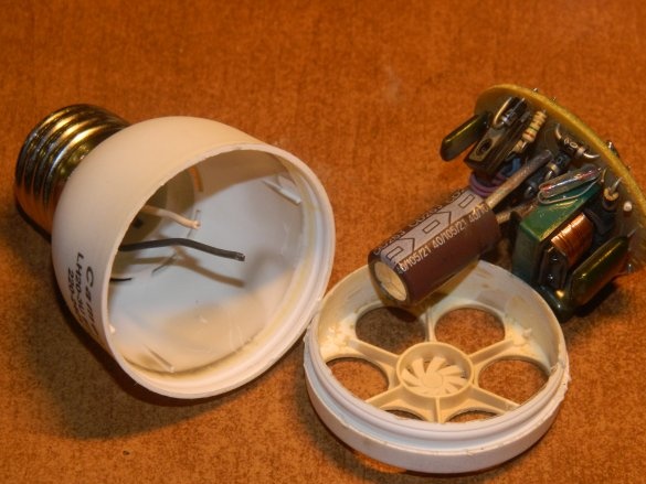
An energy-saving battery with the E27 cap was lying on the balcony (praise to the “Plyushkin” that he did not throw it out, although it was faulty!). She really was going to snap.
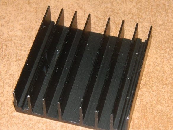
To cool the LEDs, I used a radiator measuring 50x49x15 mm.
It has 8 fins, with such a radiator the surface area is approximately 200 cm². 30 cm² is enough to divert one watt of thermal energy. Therefore, even if you file down the radiator in a circle of the inner diameter of the energy-saving cover (Ø43 mm), the area is enough to cool six powerful 3-W LEDs operating in single-watt mode.
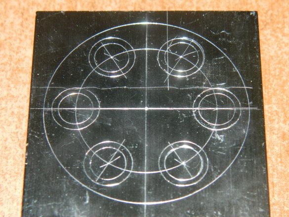
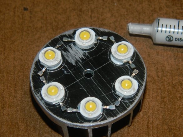
I noted the center and the seats for the LEDs, as well as the circle along which the radiator should be filed.
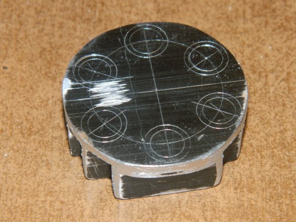
A grinder and a file sawed off a radiator up to Ø43 mm (cover diameter).
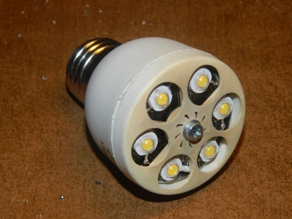
For the light bulb, I used 3-W 3HPD-3 LEDs with a thermal temperature of 4500 K (chip 45x45 mil). At room temperature 24 ° C and a current of 300 mA, the LED will warm up to 40 ° C (the area of the used radiator is 30 cm - information from the Bright Angle forum). Therefore, my radiator is enough to cool 6 of these LEDs to the working temperature zone. Using hot glue, I glued the LEDs at the places of the marking on the radiator and postponed the assembly for drying.
I drilled a Ø3.2 mm hole in the center for fixing the radiator.
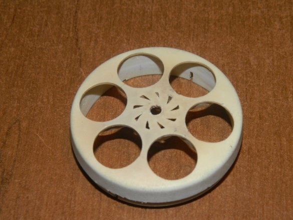
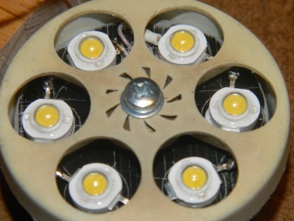
When the hot melt has dried, I started to solder the LEDs. Used MGTF wire with a cross section of 0.17 mm². To fix the radiator to the cover, I used a 6-mm spacer - now the LEDs do not protrude their covers.
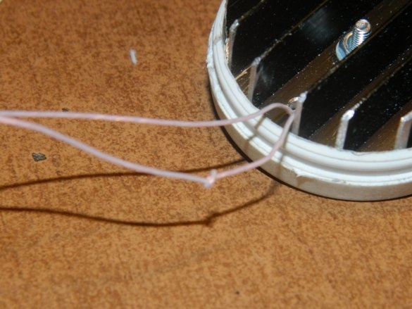
Marked "+" on the wires for subsequent installation.
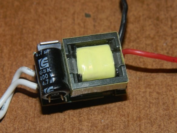
I used the HG-2205B PWM driver with the characteristics: Uin = 90-260 VAC, Uout = 10-20 VDC, Iout = 300 mA. This driver can be connected from 3 to 6 single-watt LEDs that are connected in series.
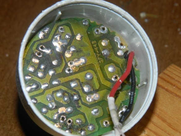
The driver is enclosureless and should be protected from short circuits to metal parts, including the radiator. Having drawn out the details from the energy saving ballast, I used the board as protection of the driver from short circuit to the radiator.
It remains only to assemble the lamp.
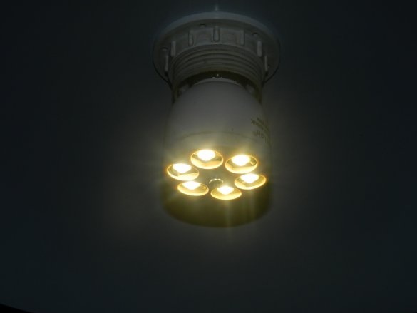
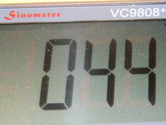
I screwed a lamp in the kitchen instead of a donut (there were no other cartridges for E27) and measured the temperature at the contact point of one LED with a radiator with a VC9808 + multimeter.
After long-term operation (within an hour and a half), the device showed 44 ° C, which is a normal thermal regime.
Visually, the lamp shines like a 60-70 watt incandescent lamp, and consumes only about 7 watts from the mains.
This lamp will go with me to the country, since I have long wanted to make lighting on the site. And there are all the E27 cartridges. Perhaps I use it to make something like a searchlight, to illuminate the parking lot of a car.


