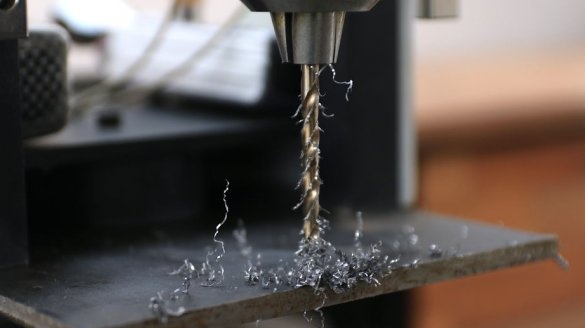
In the article "Installing a brushless motor powered by batteries" on a drilling machine, we already met this master from Pakistan. As the name implies, the master upgraded the drilling machine by installing another engine on it. Moreover, the engine was from a gyro scooter, and he made power from the battery.
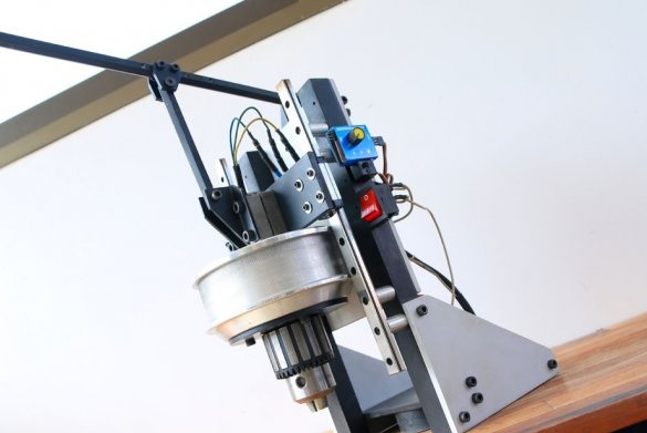
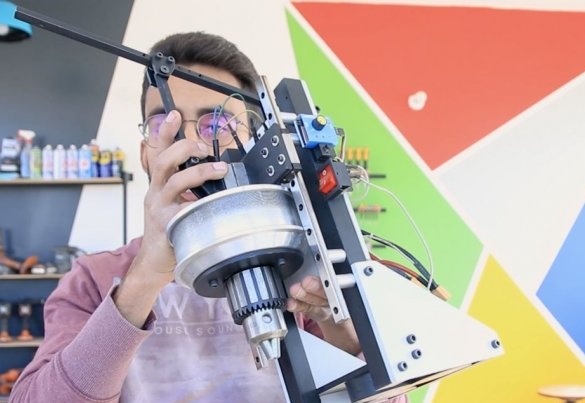
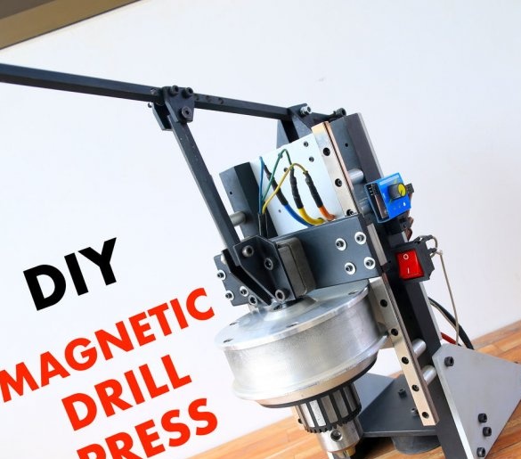
This time the master makes the drilling machine "from scratch". Feature of this machine:
-Mobility. The machine can be easily moved to another place.
-Fixing. The machine is held by electromagnets.
-Battery powered.
- Electric motor from a hoverboard.
Tools and materials:
Gyro-scooter;
-Screwdriver;
- Keys are metalwork;
-Drilling chuck;
-Drill;
-Welding machine;
-Fasteners;
-Paint;
-USHM;
-Wire;
-Connectors;
-Printed circuit board;
-Computer with software;
-Nippers;
-Soldering accessories;
-A metal sheet;
- Clamps;
-Drilling machine;
-Shlifstanok;
-Tap;
-Profile;
-Bearings;
-Aluminum strip;
-Metal circle;
-A screwdriver;
-Copper wire;
Epoxy resin;
- Hexagon;
-Mounting plates;
-Springs;
-Electronic speed controller;
-Lithium polymer battery;
-Switch;
Step One: Dismantling the Hoverboard
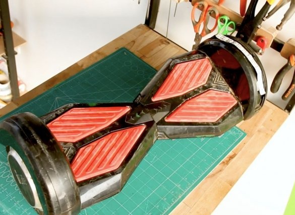
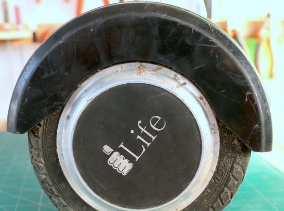
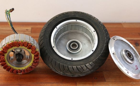
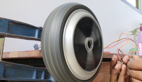
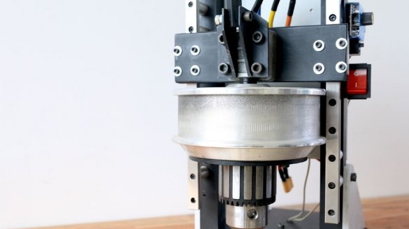
As a motor for the drilling machine, the master will use a brushless brushless motor. Such devices with 6.5-inch wheels are mass-produced in China and, according to the master, in his country there is no problem getting an idle device. The engines are located inside the wheels themselves, and they have direct drive, which means no transmission at all. These are brushless motors and they have great torque.
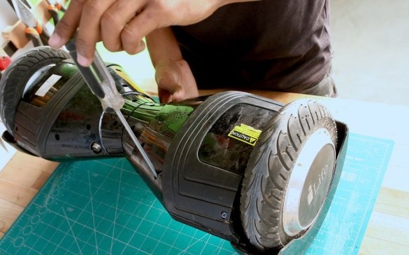
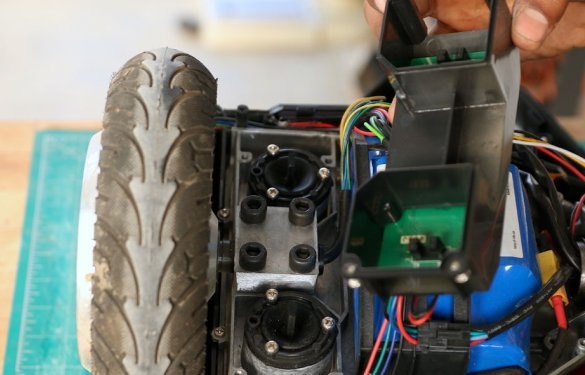
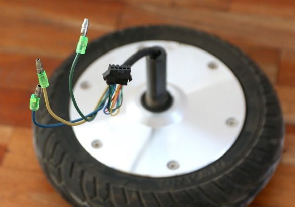
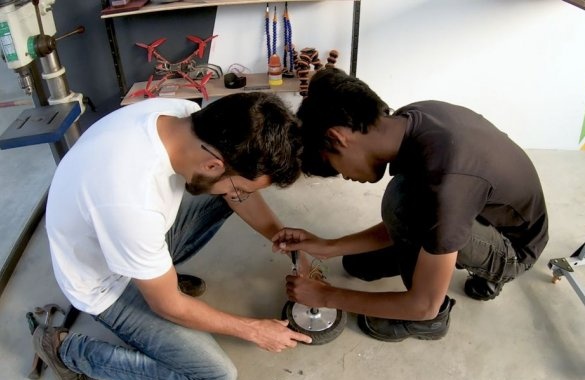
First, the master dismantles the gyro scooter and dismantles the motor / wheel.
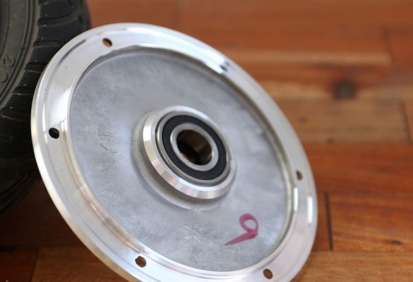
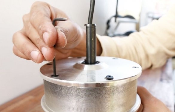
The drill chuck is planned to be installed directly on the front of the engine, but before you do this, you need to disassemble it. There are six screws on the back panel, we unscrew them.
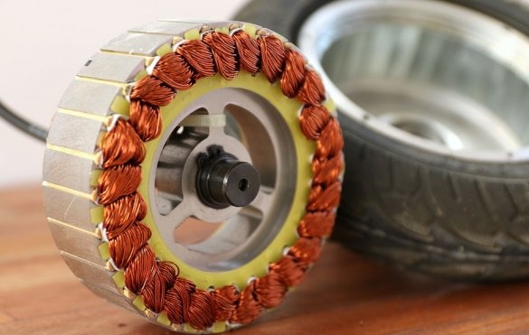
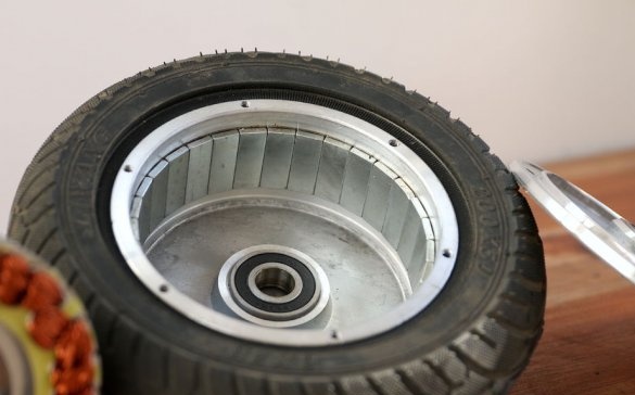
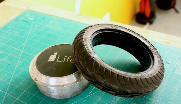
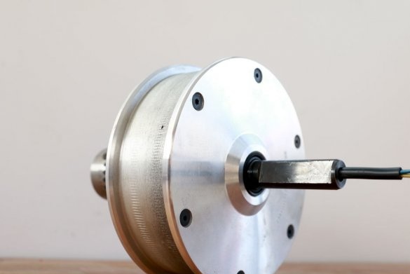
The motor / wheel has four parts: a stator, a rotor, a plate and a tire. The tire is not needed and the master removes it.
Step Two: Install Drill Chuck
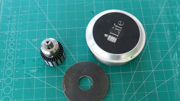
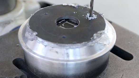
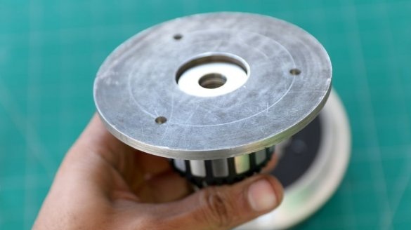
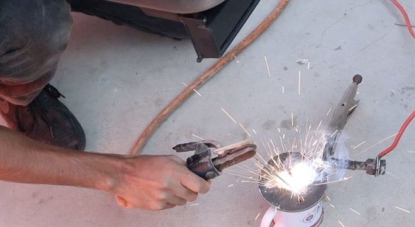
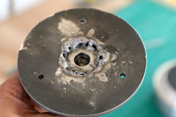
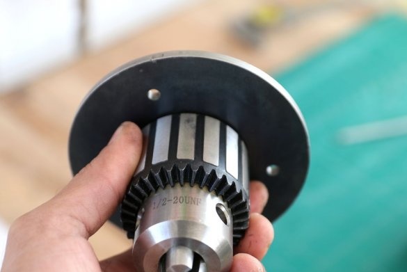
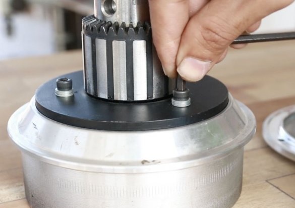
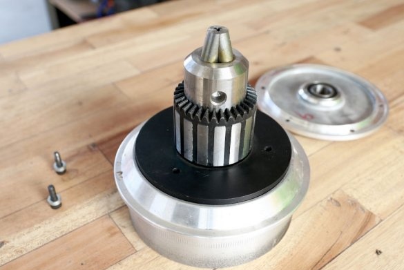
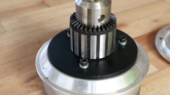
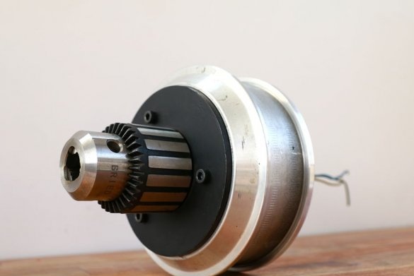
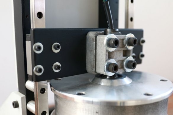
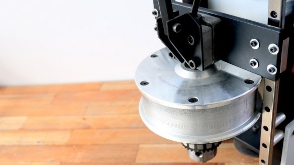
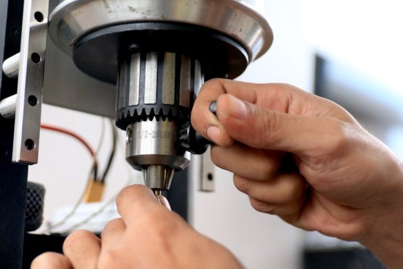
To fix the cartridge to the engine, the master uses a plate of ferrous metal.The plate is centered relative to the front of the engine. Mounting holes are drilled in the plate and front of the engine. Then the cartridge must be welded exactly in the center of the plate. Grind the welding spot. Screw plate with cartridge to engine.
Step Three: Winding
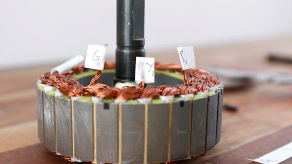
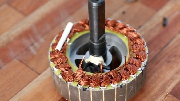
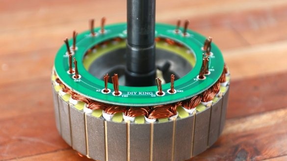
This type of engine has 27 coils. The engine is three-phase, each phase has three sets of three coils. All sets of phases are connected in series. For best performance, the wizard is going to redo the connection, making it parallel.
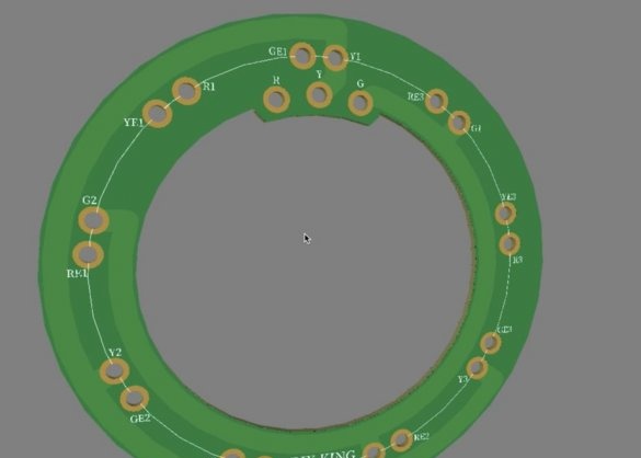
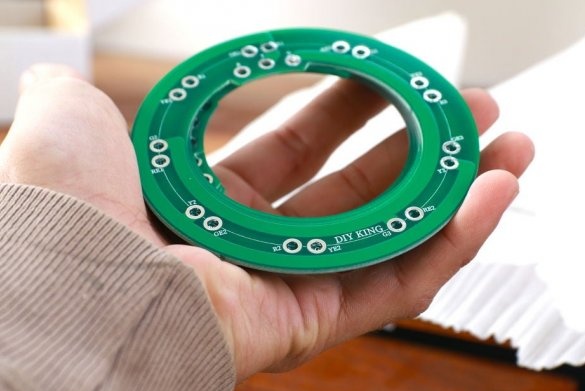
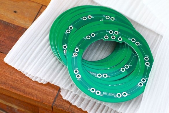
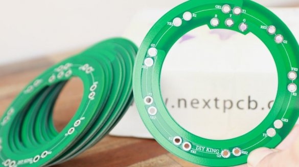
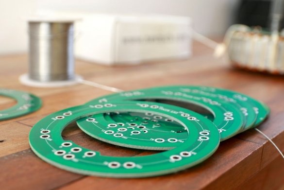
To simplify installation, the master orders printed circuit boards on the well-known Chinese site.
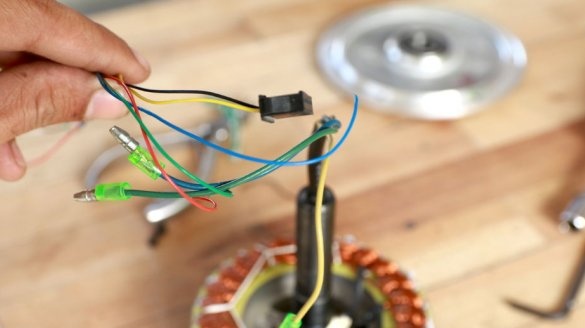
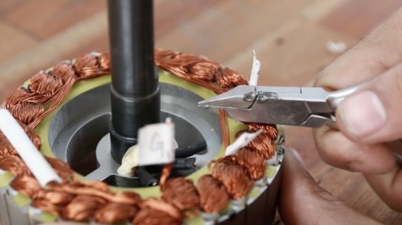
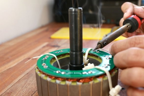
Before installing the board, you need to determine the sets related to each phase. The master labeled them with paper tapes, and the symbols R, Y, G indicate red blue and green associated with each phase. Then snacking on the mix. Strips the coating on the winding wire.
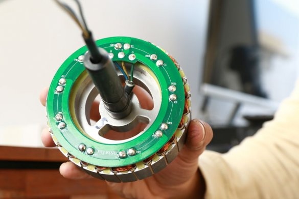
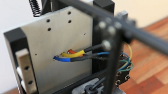
At this stage, you need to make sure that the starting point of each coil corresponds to the starting point of the corresponding phase, while the end points of all sets belonging to each phase will be connected together and shorted on the circuit board. The master solders the wires to the circuit board. The master brought the ends of the phases through a wire through the hollow shaft of the engine.
Fourth step: machine frame details
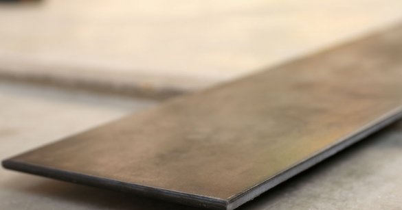
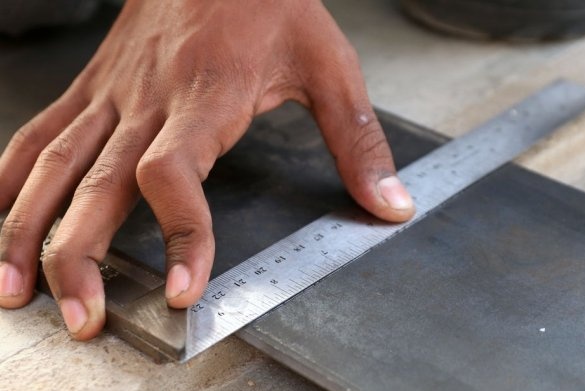
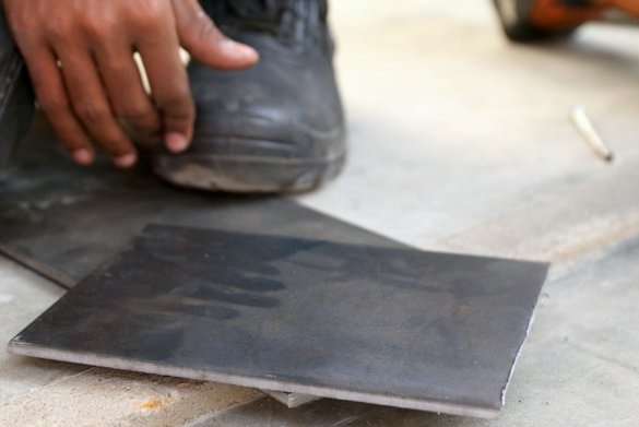
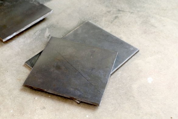
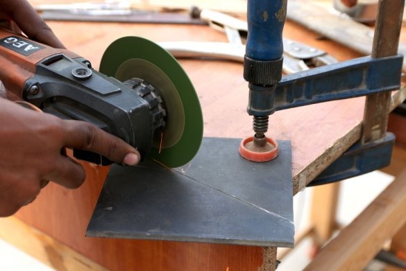
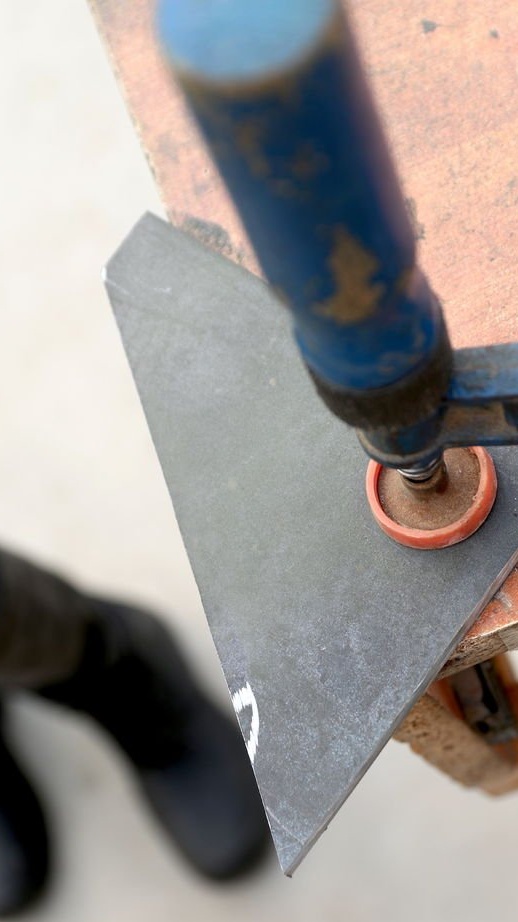
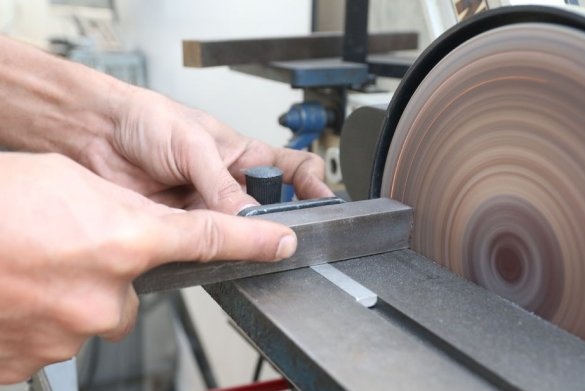
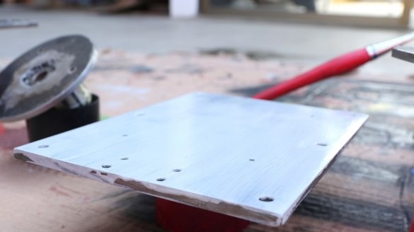
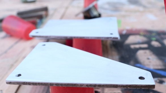
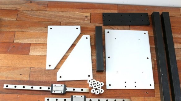
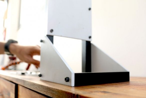
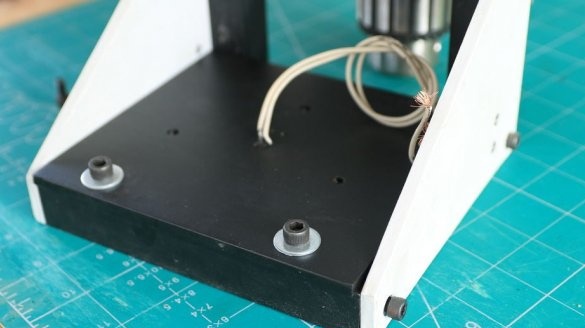
For the manufacture of a drilling machine, the master uses a metal sheet with a thickness of 6 mm. The width of the sheet is 15 cm, and this is the width of the drilling machine. For the manufacture of the front panel, sides and magnetic plate, the master cuts off the workpieces.
To connect all the details, the master uses the 22nd square.
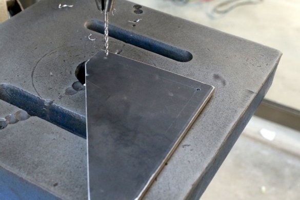
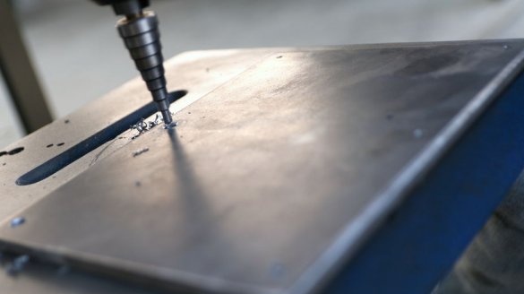
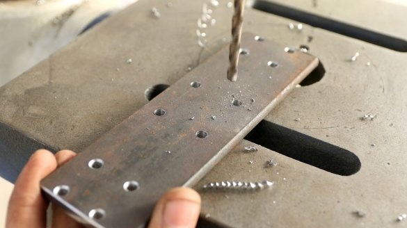
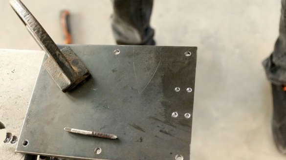
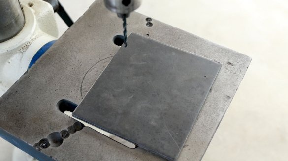
Drills mounting and technological holes in the workpieces.
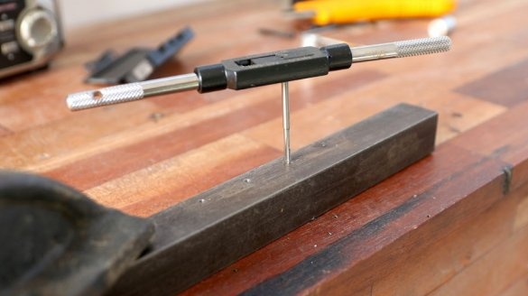
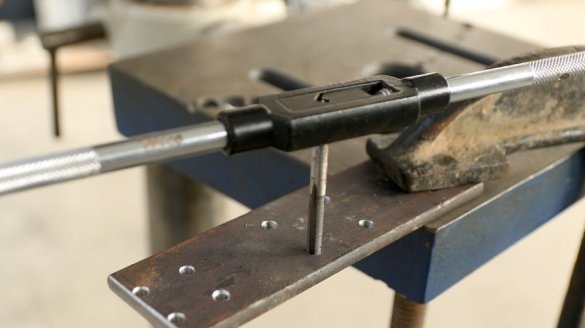
Cuts the thread.
Step Four: Painting
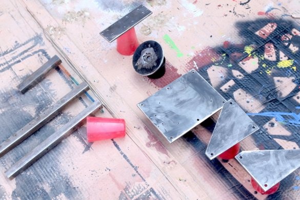
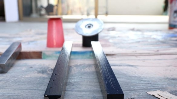
All metal parts are then polished, washed and painted.
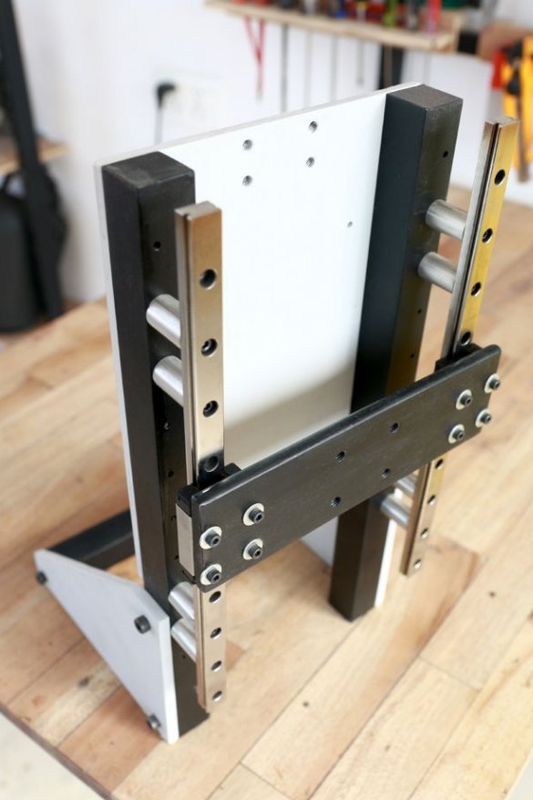
Seventh step: frame assembly
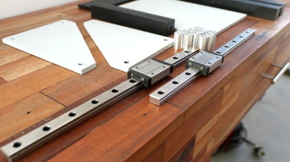
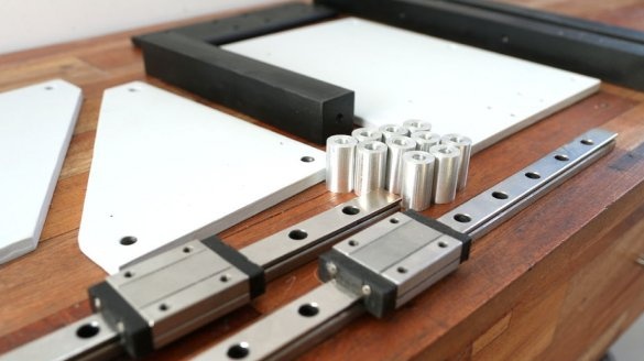
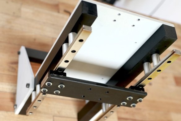
In the design of the machine, the master uses aluminum guides and spacers.
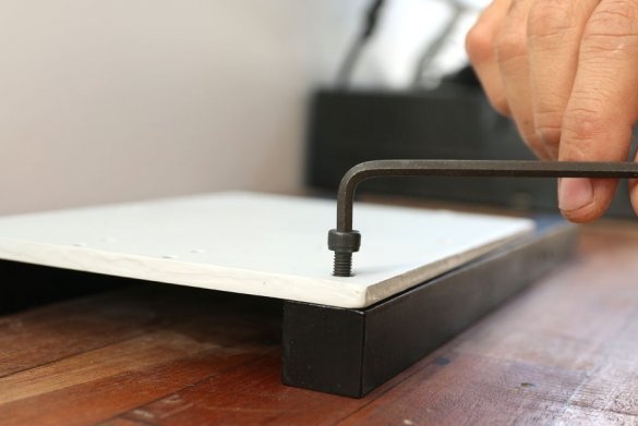
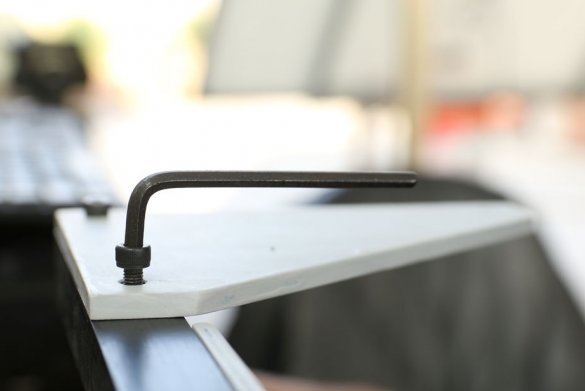
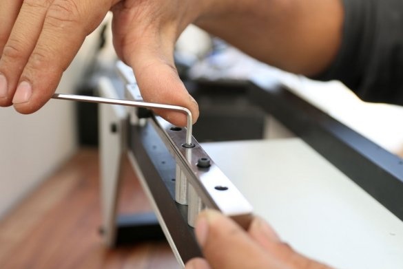
As soon as the paint has dried, the master collects the bed using hexagon screws. First sets the front panel into place, and then a small metal bar. Later, this bar will hold the electromagnetic plate.
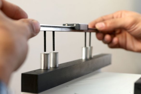
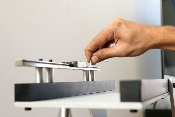
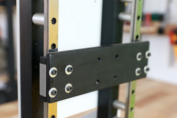
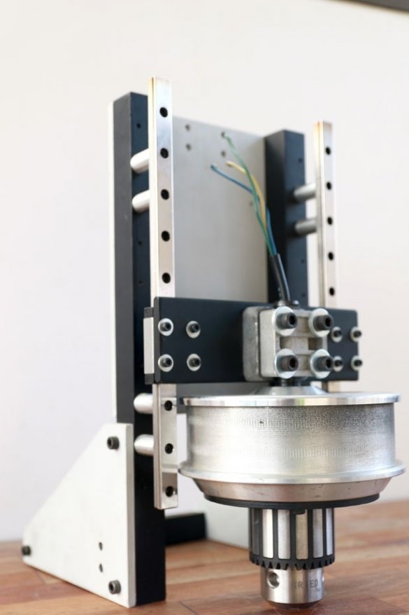
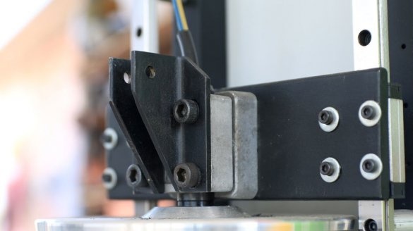
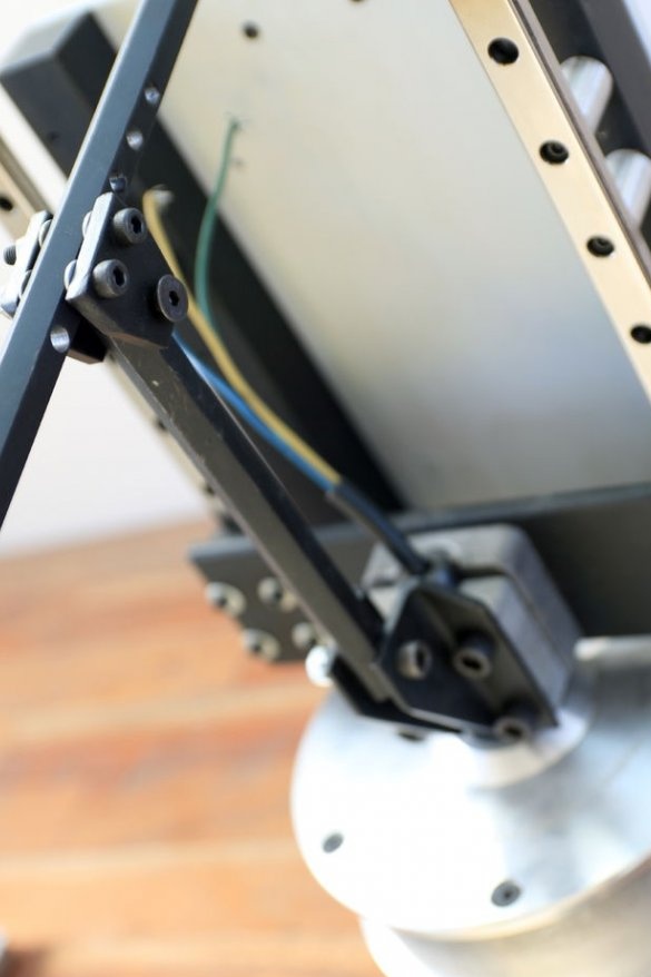
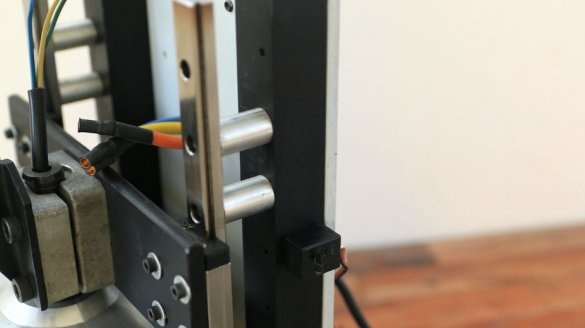
Further, for vertical movement of the engine, the master uses 15 mm linear bearing bearings and a pair of linear bearings. They are usually used in heavy industrial machines, such as CNC and lathes, and have good load bearing capacity. To ensure a clearance between the structure and the drum of the engine uses aluminum struts. It also installs linear guides on top of metal rods, installs a linear bearing and an engine mounting plate.
Step Eight: Electromagnets
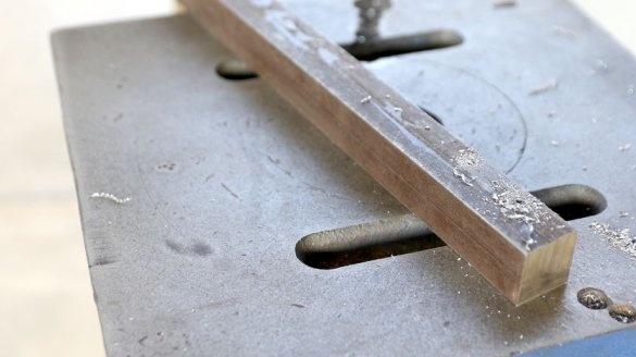
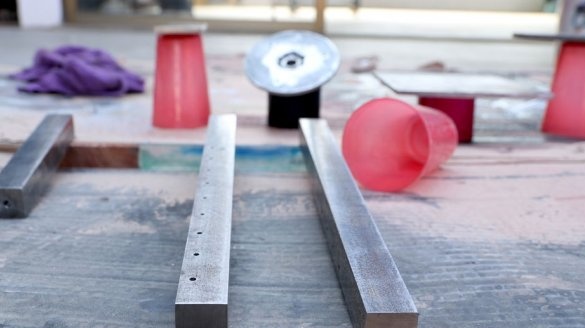
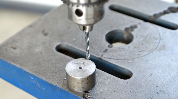
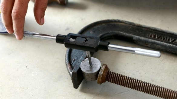
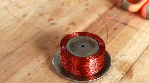
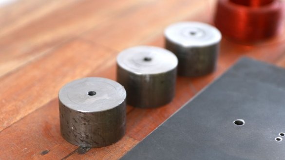
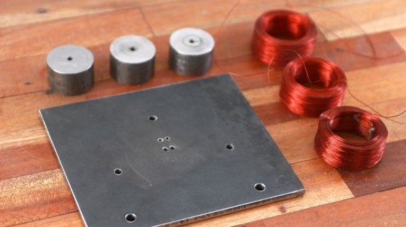
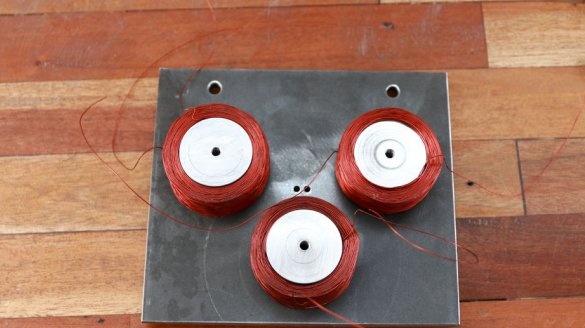
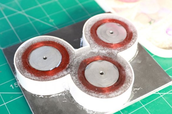
Using electromagnets, the drilling machine will be held on the metal surface of the workpiece or table. For its manufacture, the master uses a metal plate 6 mm thick and three metal rods cut to a length of 22 mm. It is necessary to precisely adjust the length of the rods (cores), it is with them that the electromagnet will “stick” to the metal. The master drills a hole in the rods and cuts the thread.
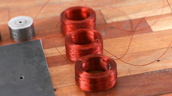
Since the master decided to use a 6S lithium battery for this drill press, he has almost 22.2 V for the coil to work. After several calculations, he settled on a magnetic coil with a rated power of about 100 W (22.2 V and almost 5 A). He uses 100 grams of enameled 27 gauge (0.361 mm) copper wire on each core to wind the coil.
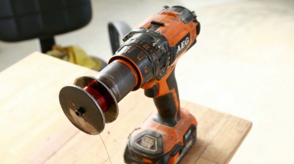
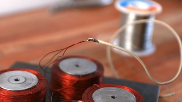
With the help of a drill, the master winds three coils.
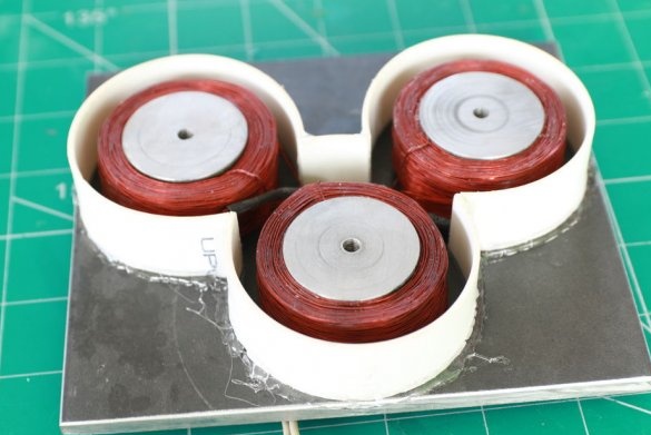
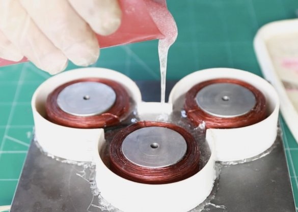
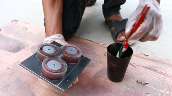
To protect the coils from damage by metal shavings that will occur during drilling, the master sets a shape around the coils and fills them with epoxy.
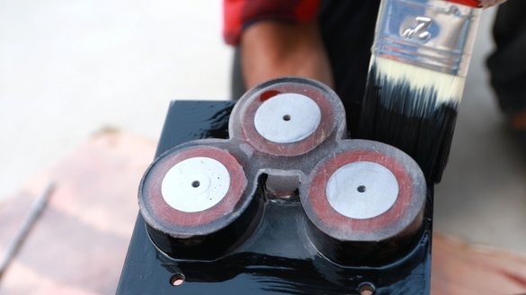
After the resin hardens, the plastic is removed, and the plate is painted.
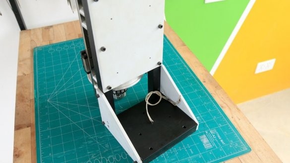
Now you can install the electromagnet on the machine.
All three coils are connected in parallel, and together they consume about 5 A at a voltage of 22 V, and the electromagnet is very strong. The master tested it on a 6 mm metal plate, and could neither move the device nor disconnect it from the metal sheet when voltage was applied to the coils.
Step nine: assembly and installation of the engine
The master assembles the engine and installs it on the machine. The motor fits perfectly in the center of the linear guides with a gap of 2 mm on both sides.
Step Ten: Pen
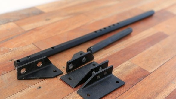
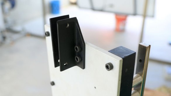
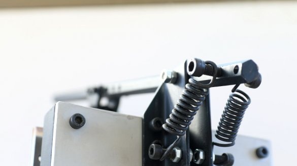
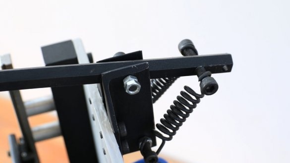
To move the engine vertically, you need a handle. The master makes the handle from a hexagon and fixes it with the help of fasteners made of a metal plate. To return the handle and, accordingly, the engine to its original position, two springs are installed.
Step Eleven: Electronics
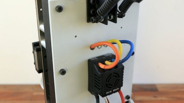
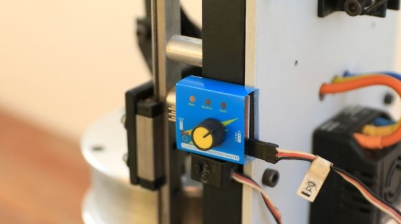
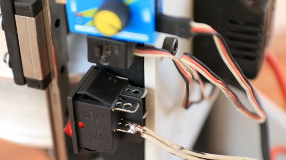
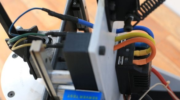
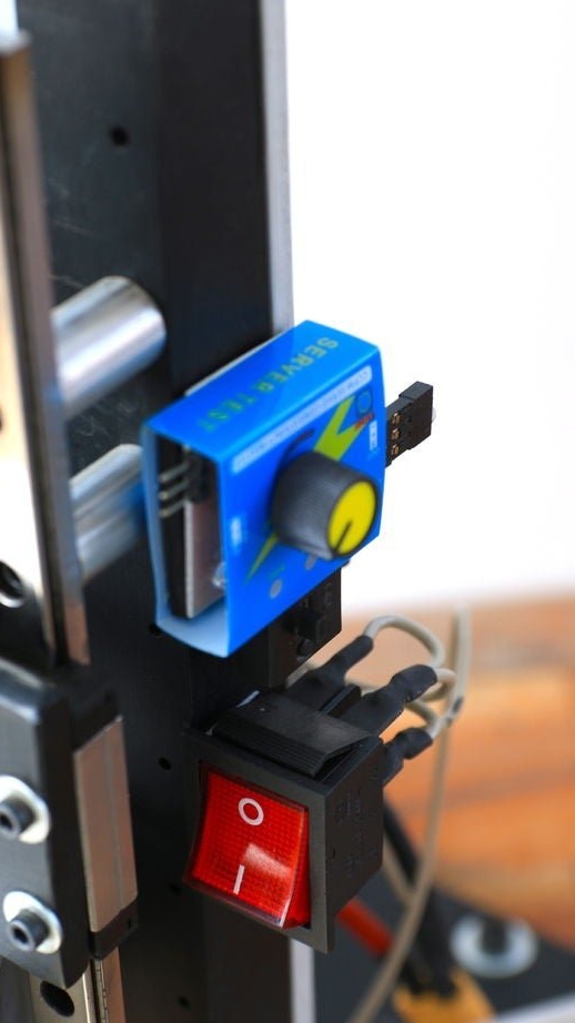
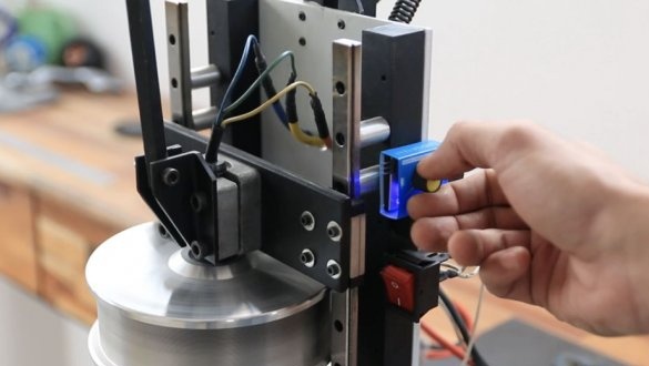
The master uses ESC to control the engine. Speed is controlled by a servo tester.
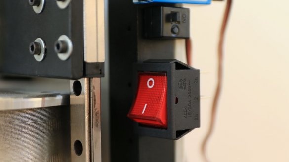
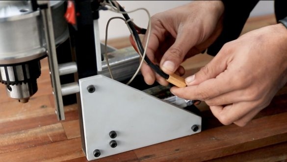
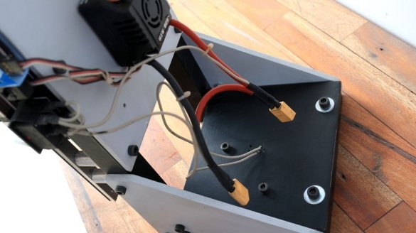
In addition, it uses a 20 A SPST switch to power magnetic coils. The input for ESC and coil is connected to the XT-60 connectors.
To power the drilling machine, two lithium-polymer batteries 3s 5200 mAh are used, which operate at a discharge speed of 30C. The machine can run 15 minutes continuously on these batteries.
Step Twelve: Testing
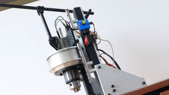
The master is very pleased with the result. The machine turned out compact and not heavy. The use of electromagnets allowed us not to fear that he would fall forward due to an incorrect center of gravity.
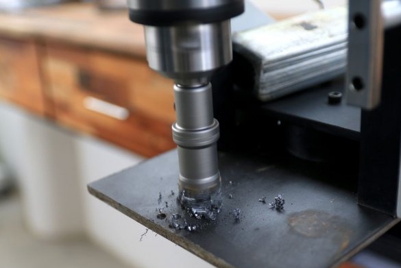
With the help of a servo tester, the rotation speed can be precisely controlled. The master began drilling with a 5 mm hole and finished with a 22 mm hole. The machine did a great job with this job.
The whole process of manufacturing such a machine can be seen in the video.

