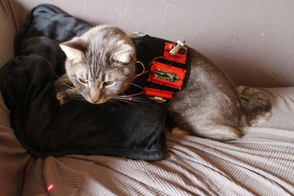
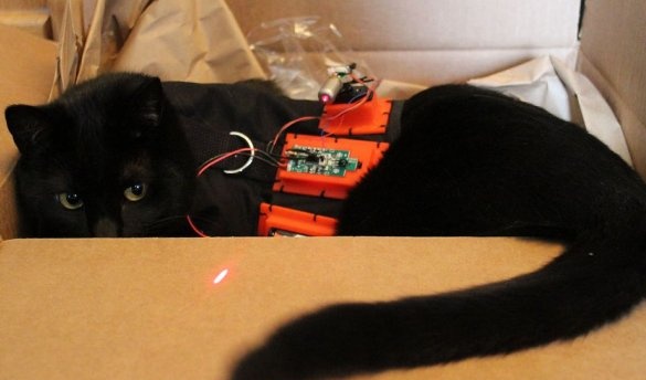
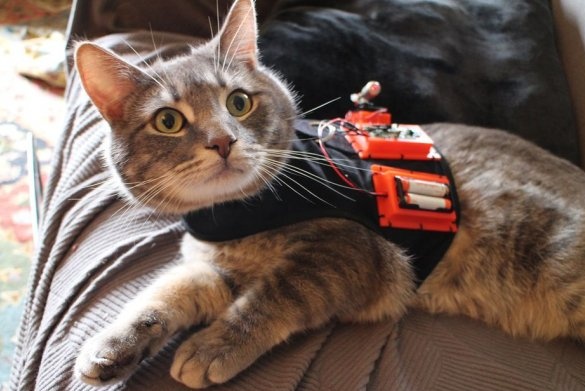
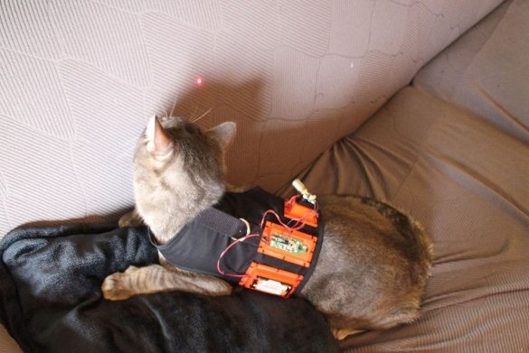
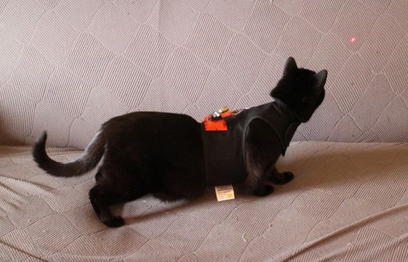
Almost all cats and some dogs like to “hunt” for a laser dot. Usually the laser pointer is in the hands of a person, the Master decided to fix the pointer on the animal and control it remotely.
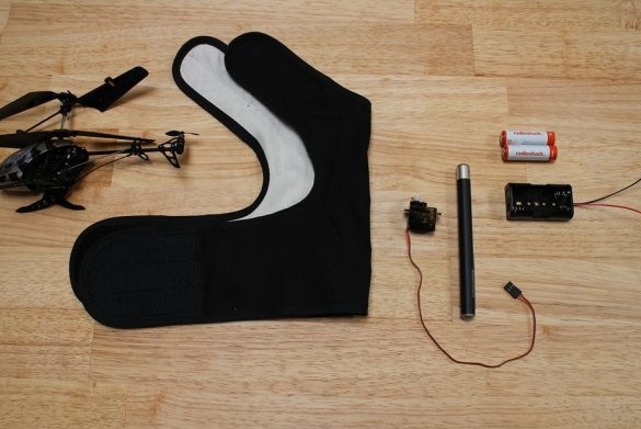
Tools and materials:
-Radio module with remote control (from a toy helicopter):
-Laser pointer;
-Servo;
-NPN transistor;
- Resistor 1 kOhm;
-AAA battery holder;
- AAA battery - 2 pcs;
- AA battery - 6 pcs;
Harness for the cat;
-Thread;
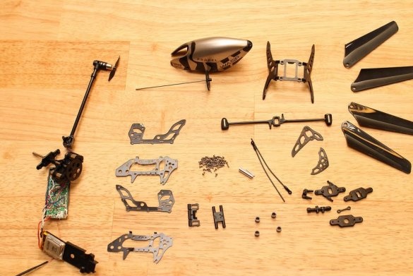
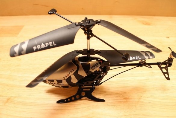
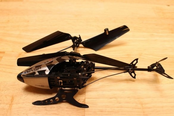
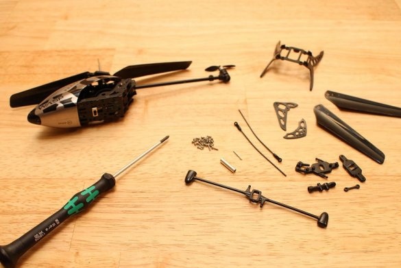
Step one: disassemble the helicopter
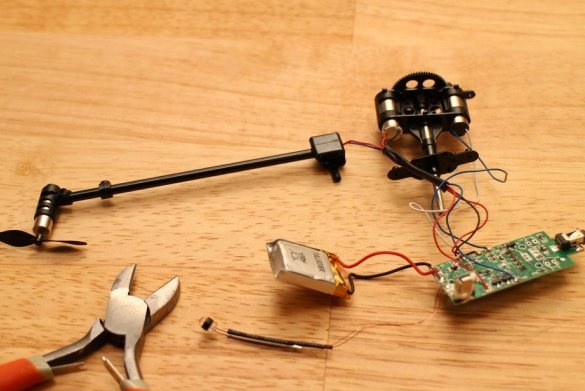
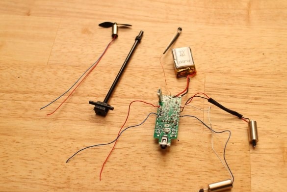
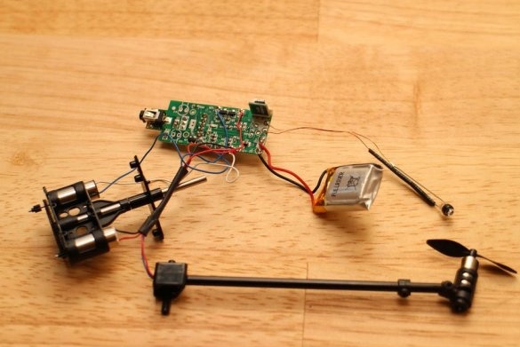
First you need to disassemble the helicopter. The helicopter has a control board with a radio module. The master disconnects the battery and motors from the board.
Step Two: Servo
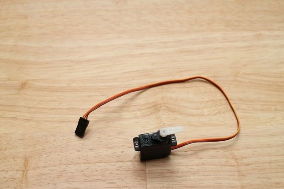
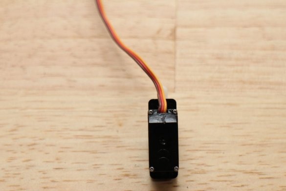
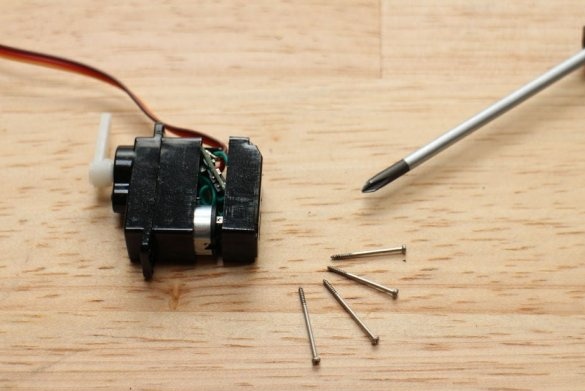
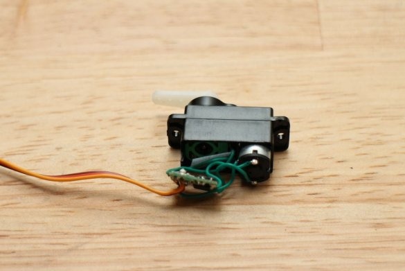
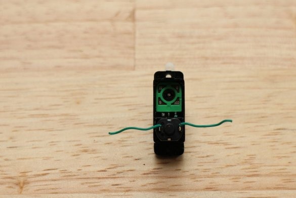
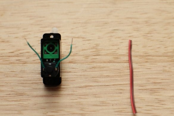
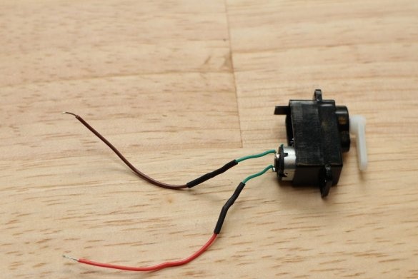
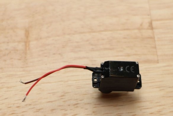
The servo needs to be slightly modified. Disassembles the servo drive and dismantles the wires soldered to the board.
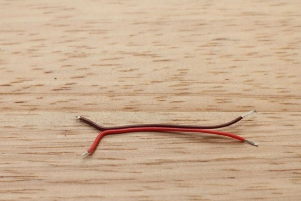
Directly solder other wires to the motor contacts.
Step Three: 3D Printing
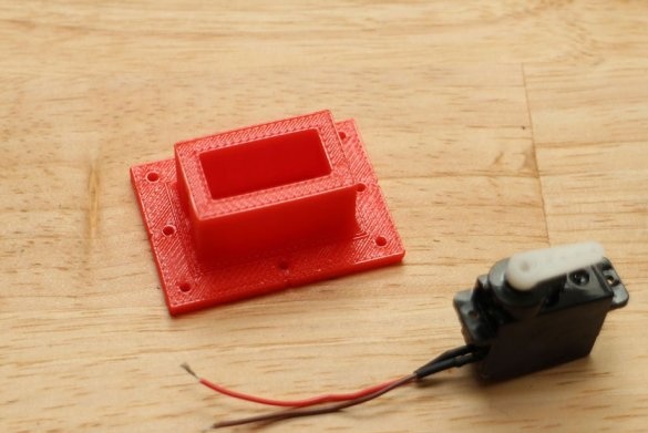
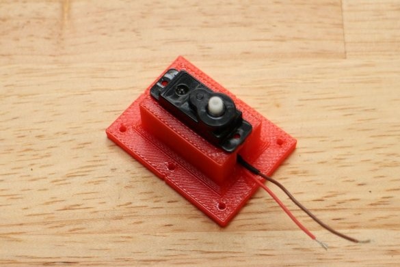
On a 3D printer, prints out the servo mount. Installs the servo in the mount.
Micro Servo Mount.stl
Step Four: Laser Pointer
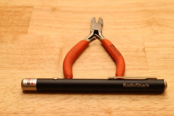
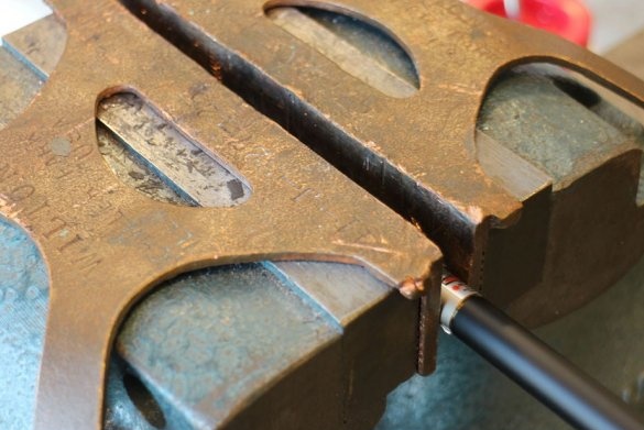
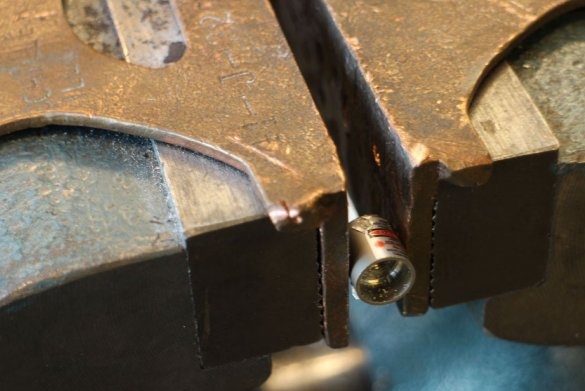
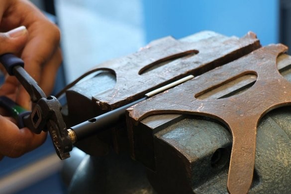
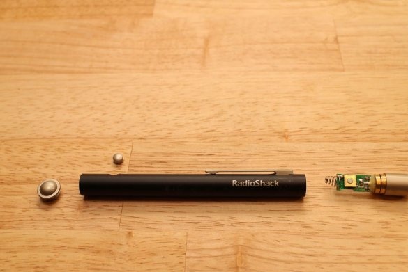
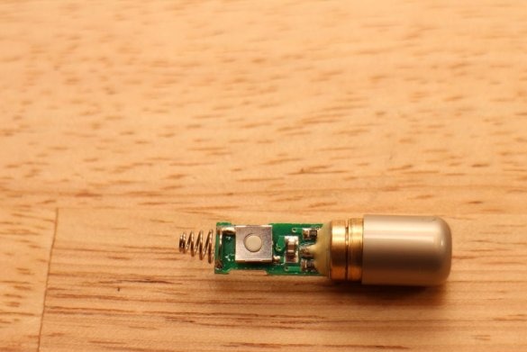
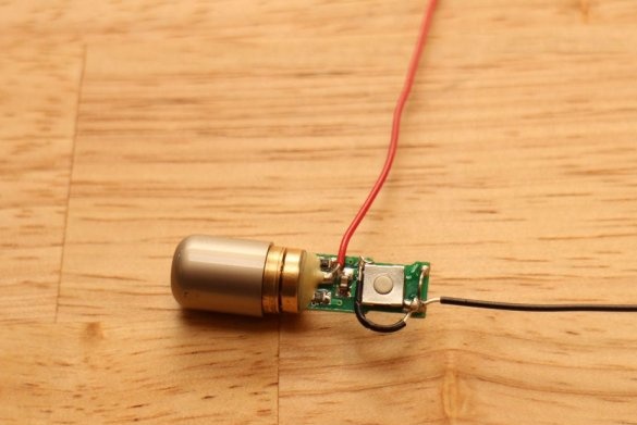
The laser pointer is too bulky to fit on a small servo, so we need to remove the diode and driver from the housing tube.
As soon as the diode is free, it removes the spring attached to the end.
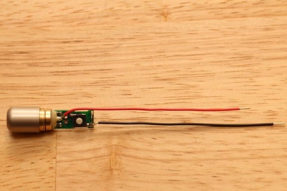
Solder two wires to the board and jumper to the power button. Those. normal position "closed".
Step Five: Build
The original battery that powered the helicopter was rechargeable, but with a small capacity. In addition, the laser driver runs on ~ 3 volts, and the LiPo battery produces between 4.2 volts and 2.7 volts, which can damage the driver. Initially, a servomotor required 4.5 to 6 volts, but the motor would run without load at much lower voltages. Therefore, the master decided that two AAA batteries would be enough.
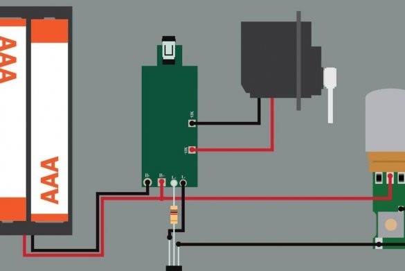
The master solders the wires from the battery pack with contacts B + and B- on the main board. Solder the anode (red) wire from the laser to pin B +.
Solder the cathode (black) wire from the laser to the collector of the transistor (the leftmost pin when looking at the flat side).
Solder a 1K resistor between the L + pad and the base of the transistor (middle pin).
Solder the output of the emitter of the transistor (the rightmost output, if you look at the flat side) to the L board.
Solder the motor wires to the M + and M- contacts, respectively. Polarity does not matter.
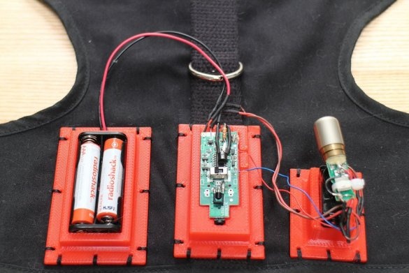
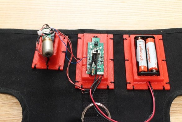
On a 3D preprint, prints out the details and installs the board and battery.
AAA Battery Mount.stl
RC Electronics Mount.stl
Step six: train the cat
If you immediately put on a cat harness, then he obviously will not be happy. This harness is used, together with a leash, for walking cats and small dogs. The manufacturer’s website says that you need to gradually accustom the animal to wearing a harness, dressing for several minutes and gradually increasing the time.
After accustoming the animal to wearing a harness, the master fixes the device on it and puts it on the cat.
All is ready. You can control the laser using the joystick or install the laser at one point.
Below you can watch a video with an example of the assembly and operation of the device.

