
I recently built dozens of robots, mostly inspired by the wonders of BEAM robotics. If you are not familiar with this technology, BEAM is a special method for constructing robots with emphasis B - biology, E - electronics (electronics), A - aesthetics (aesthetics) and M - mechanics (mechanics). This is the acronym BEAM. What separates this technology from other approaches is the use of only radiation energy for nutrition (mainly solar energy), the disposal of various materials (reuse) and minimalism. Although I have adopted these principles, my own robots were not quite in the spirit of BEAM (they were powered by a battery).
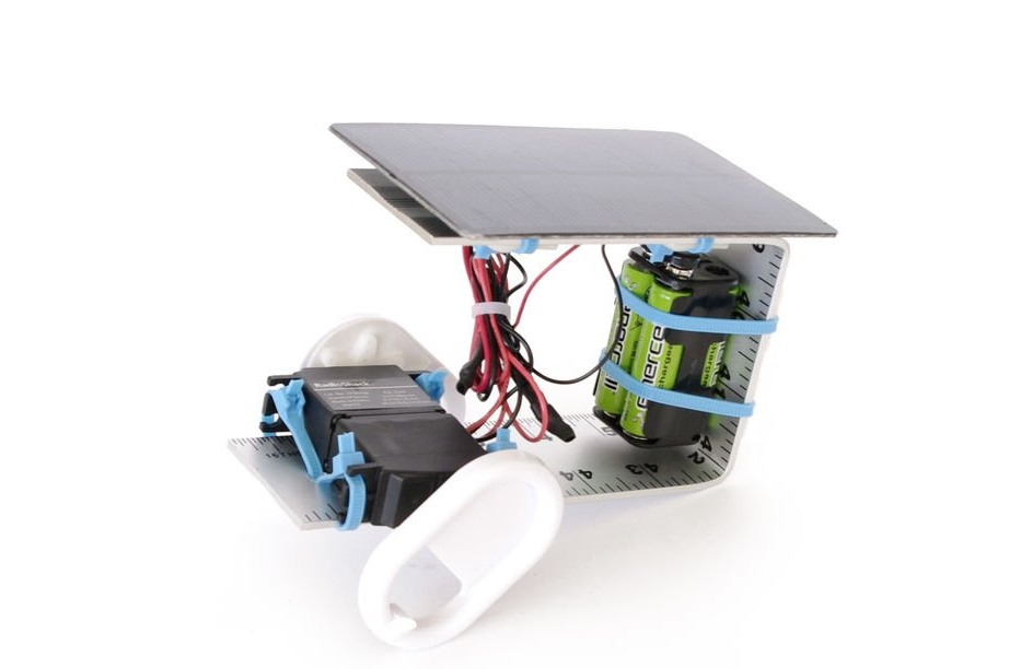
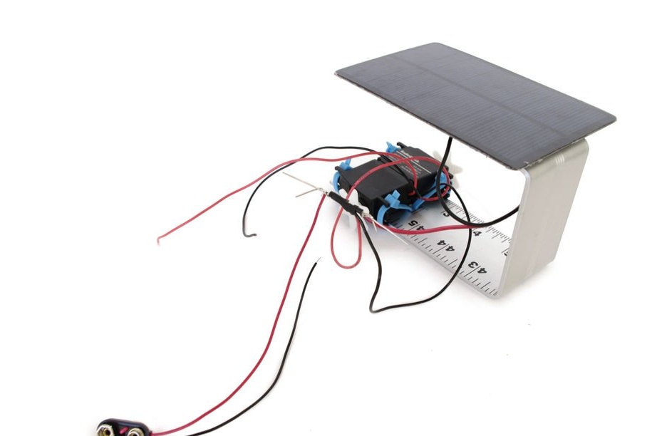
Since BEAM robotics inspired me seriously, I wanted to make a solar-powered robot. But instead of just making a BEAM robot, I decided to integrate a solar panel into the robot of my usual style. Instead of fully powered by the sun, I decided to build in rechargeable batteries. That is, my robot can be powered either from a battery or from a solar panel, depending on which power source is currently more powerful. The solar panel also charges the batteries when sunlight hits it. This allows the robot to move both in the light and in the shade.
I think this approach successfully combines two styles, and this is an interesting experiment in the construction of robots.
Step 1: Materials
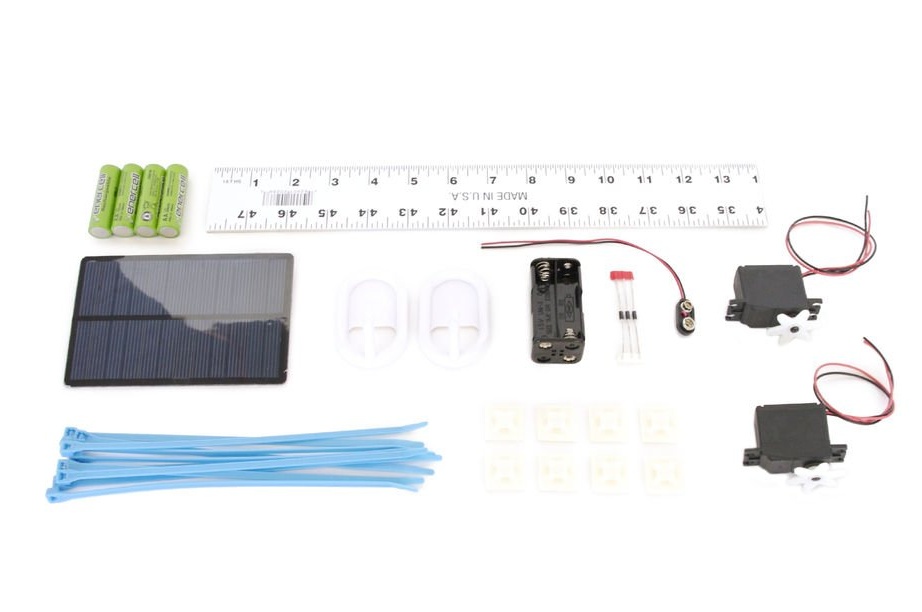
You will need:
(x1) Solar panel
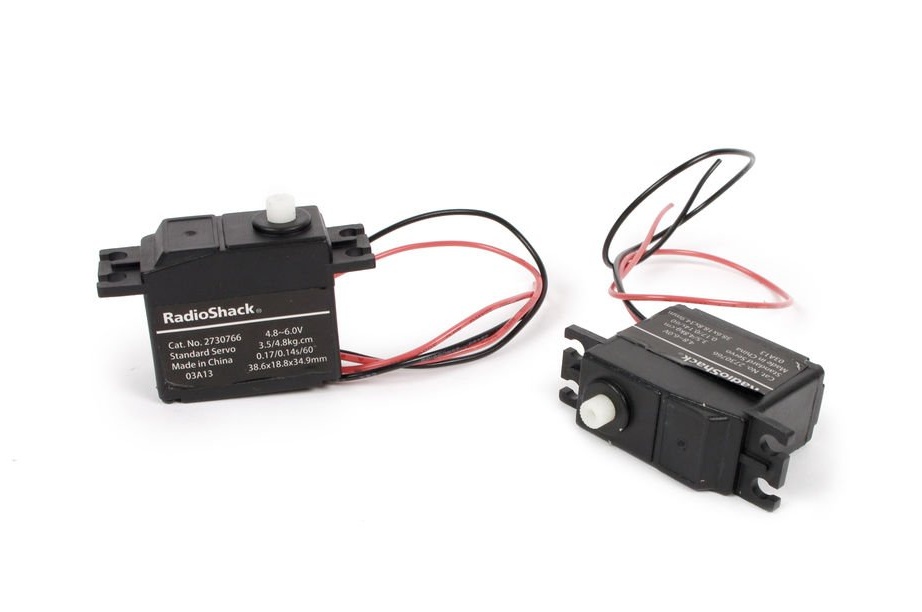
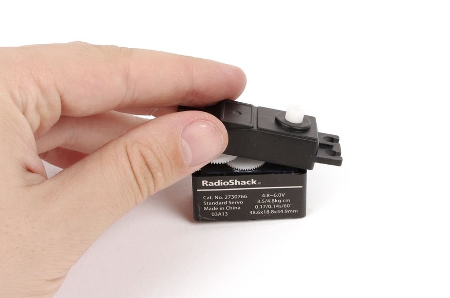
(x2) Standard servomotors
(x3) Schottky Diodes 1N5817 - NTE578 equivalent
(x1) 9V battery
(x8) Rechargeable AA batteries
(x1) 8 x AA battery pack
(x12) Base for clamps
(x1) Ruler (30 - 50 cm)
(x2) Wall-mounted adhesive hooks
(x1) Plastic clamps
(x1) Heat Shrink Tubing
Step 2: Modify the Servo
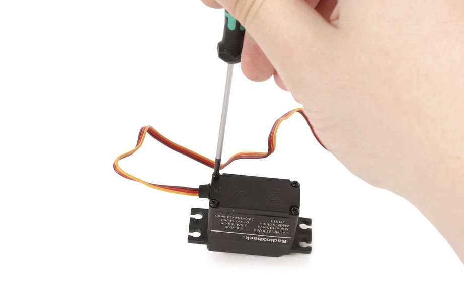
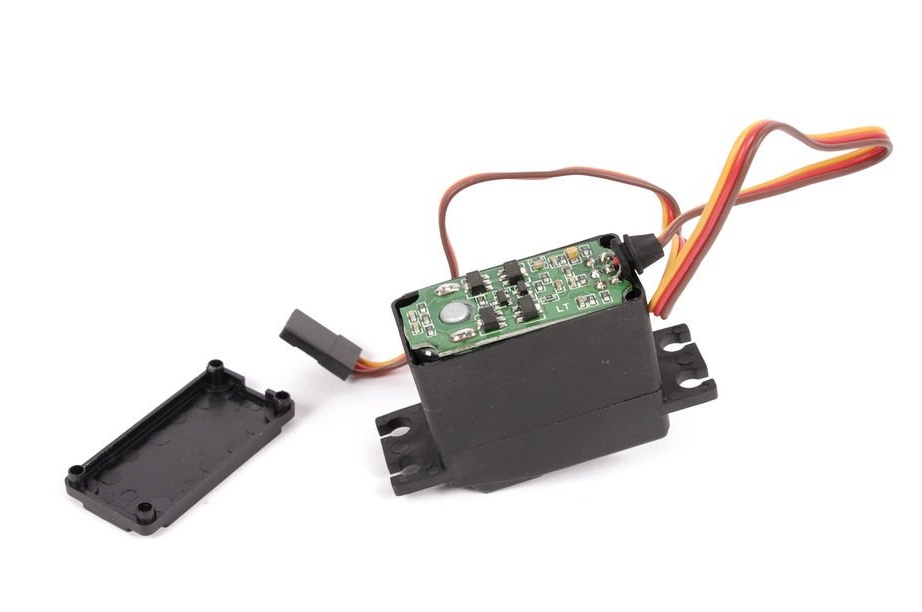
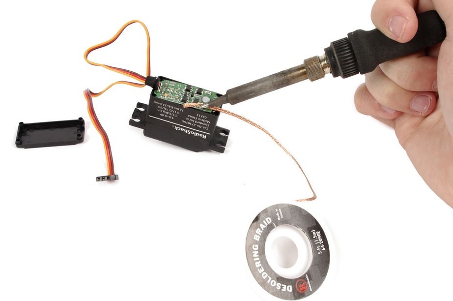
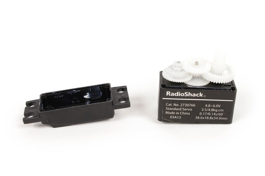
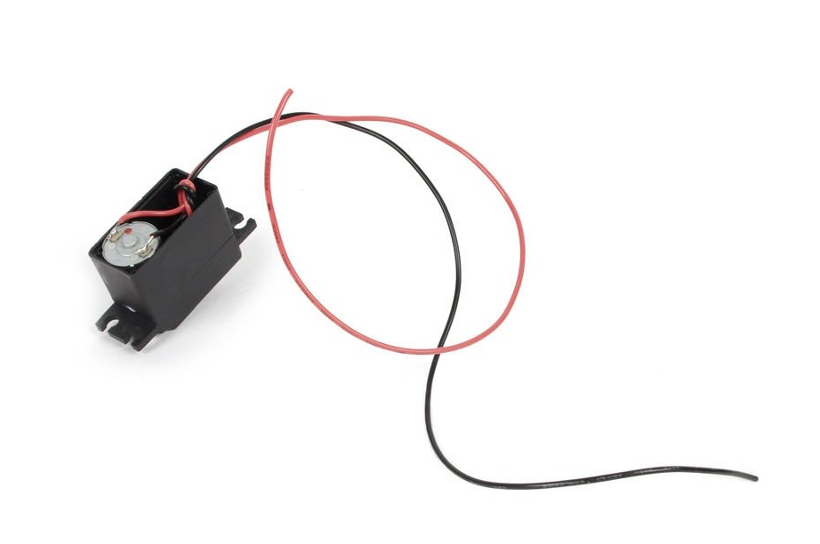
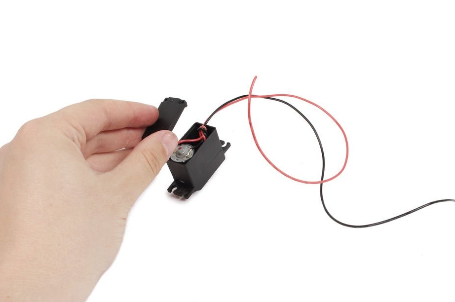
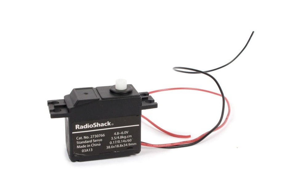
Open the servo housing by unscrewing 4 screws on the bottom panel. Unzip the board inside and connect the red and black wiring to each terminal of the drive.
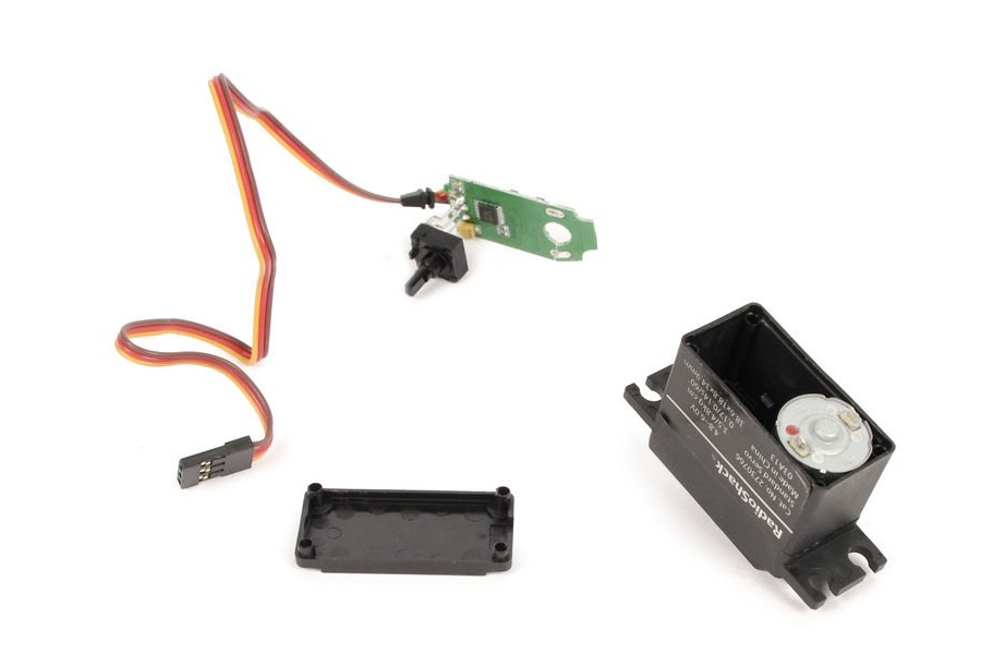
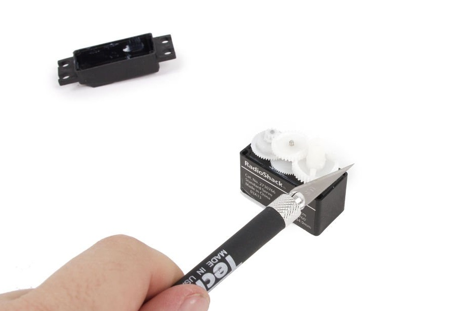
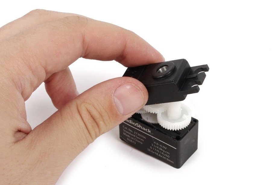
Open the gear drive and find the gear with a small plastic cap that prevents continuous rotation. Cut off the cap from the gear.
Step 3: Drill
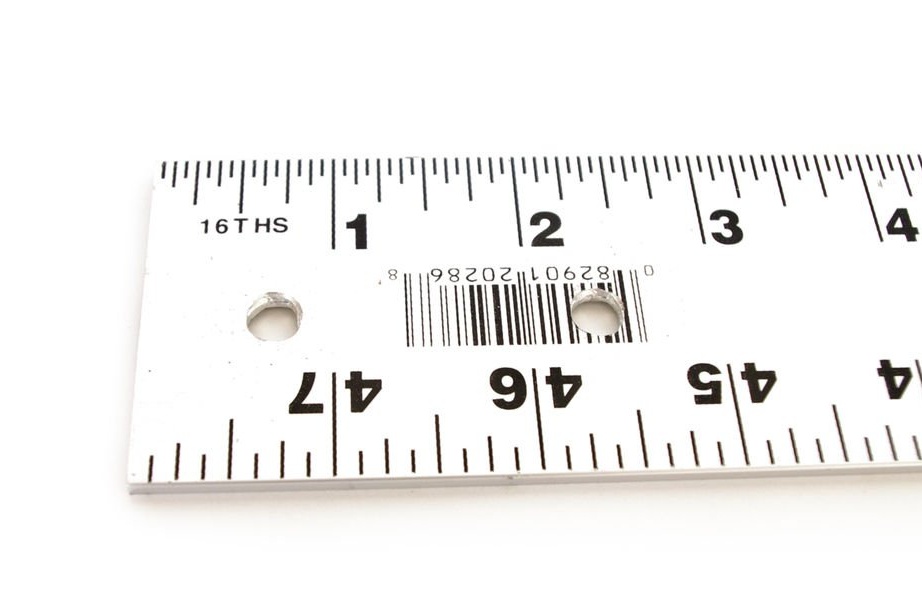
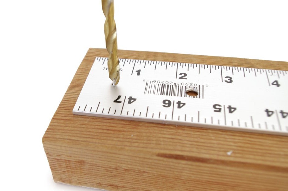
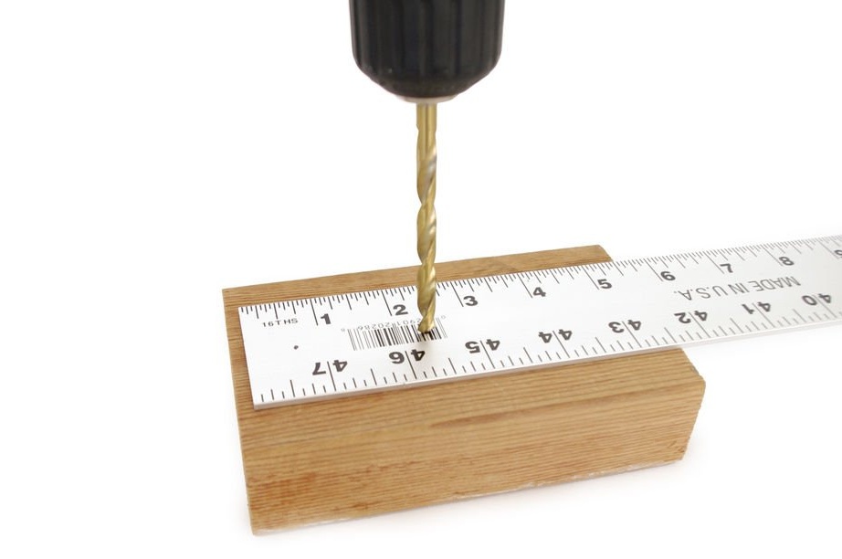
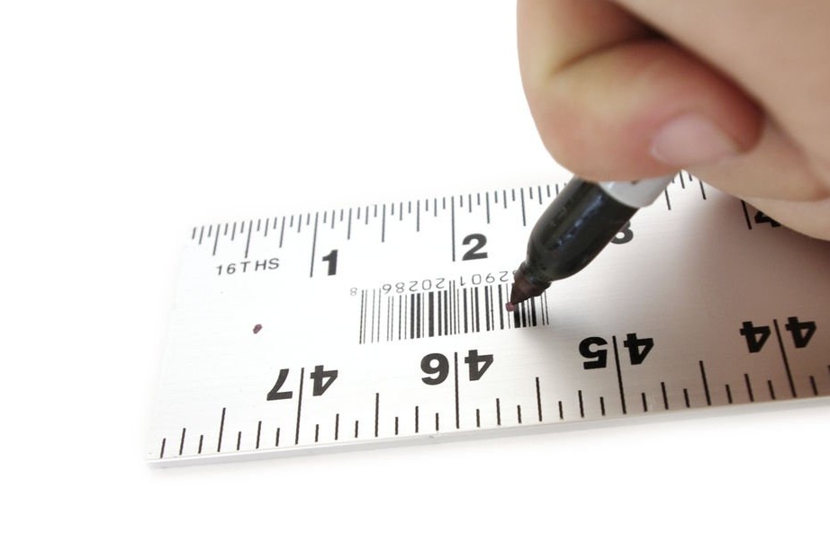
Drill a quarter inch (6.3 mm) hole in the middle of the ruler, about 15 mm from the short edge. Drill a second hole about 60 mm from the same edge.
Step 4: Bend
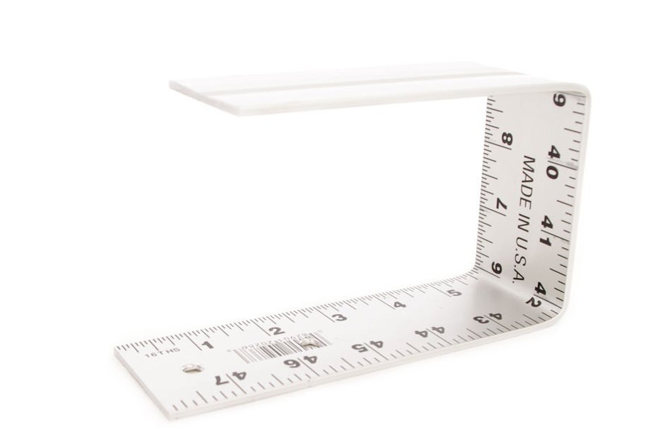
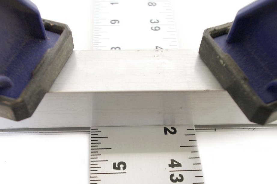
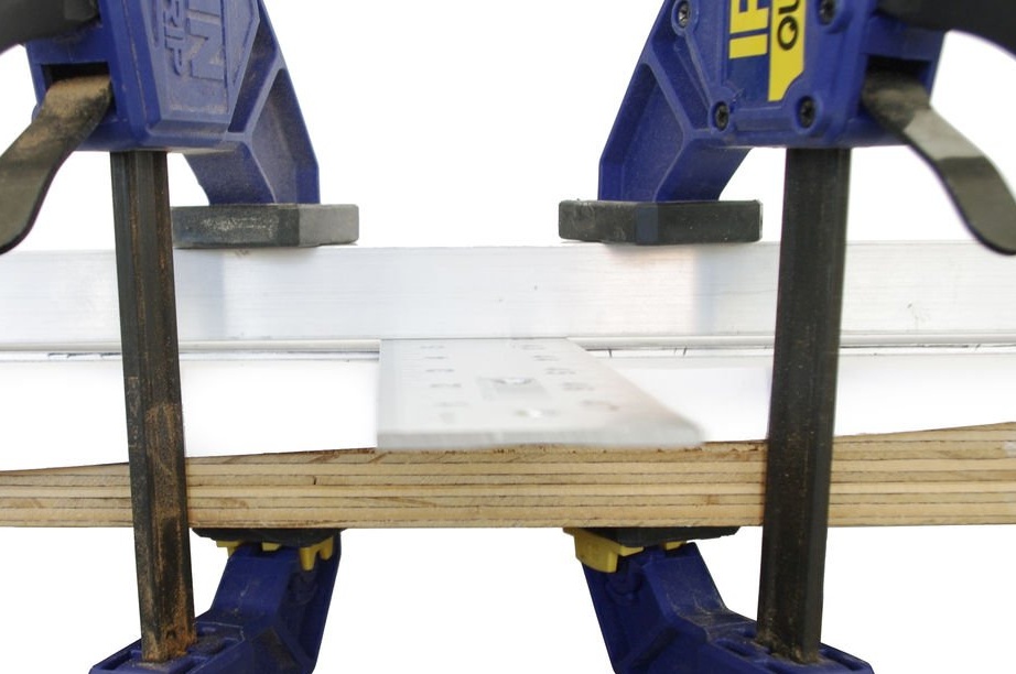
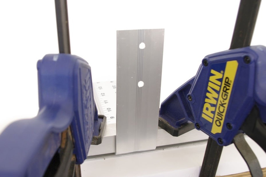
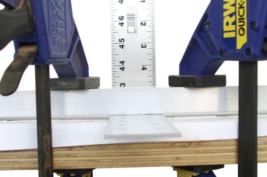
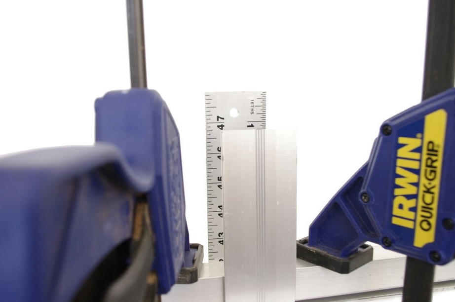
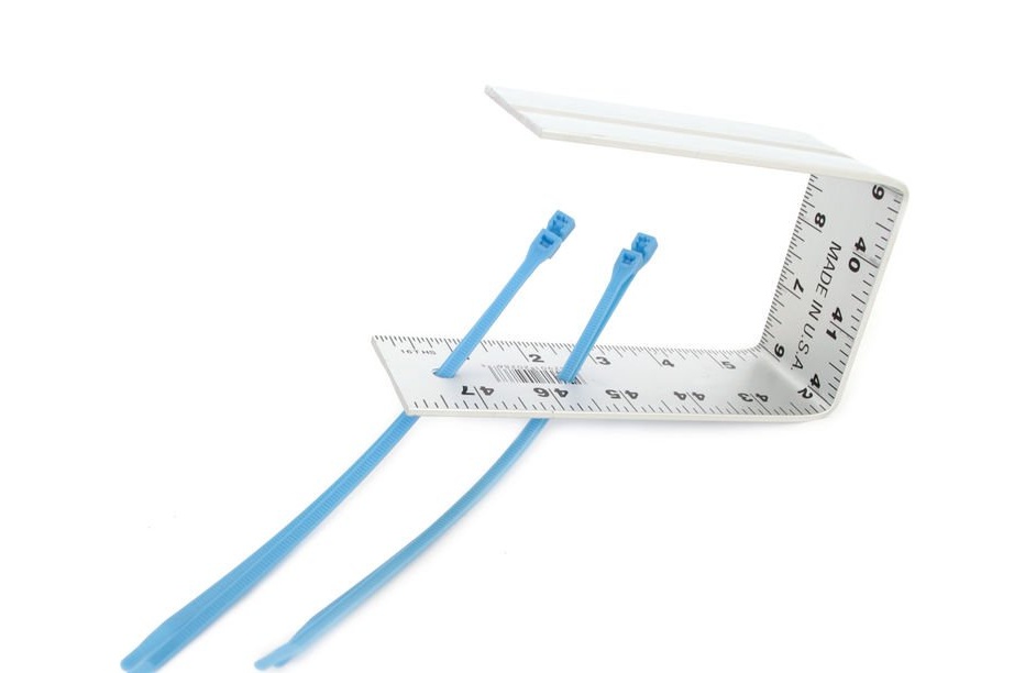
Using a vise or two metal plates clamped on the edge of the table, bend the ruler at an angle of 90 degrees at a distance of 15 cm from the edge in which the holes were drilled.
Make the same bend at an angle of 90 degrees at a distance of 15 cm from the other edge. You will get a figure in the form of the letter P.
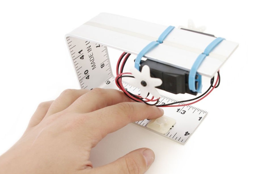
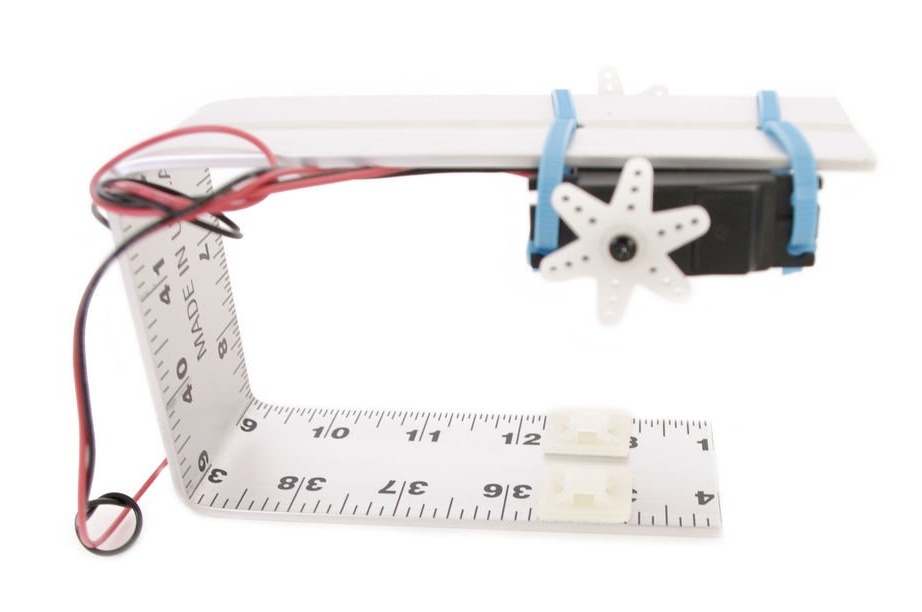
Step 5: Connection
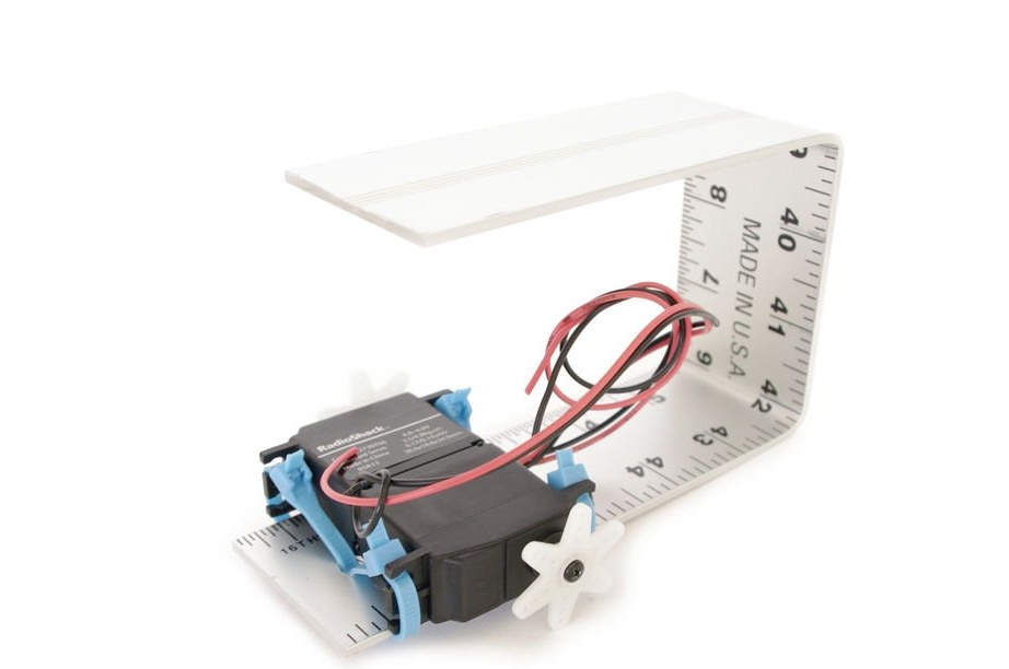
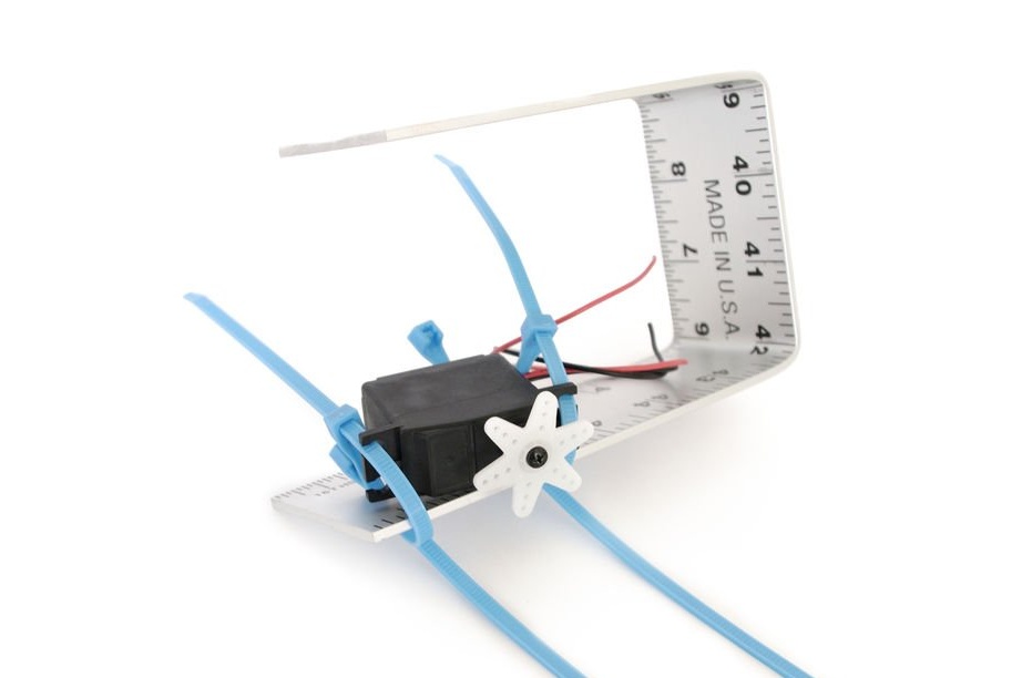
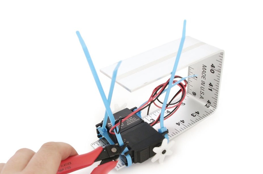
It is necessary to fix the servos on the line with plastic clamps, through drilled holes. Servomotors must sit with their backs to each other.
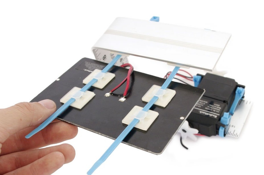
Step 6: Base for clamps
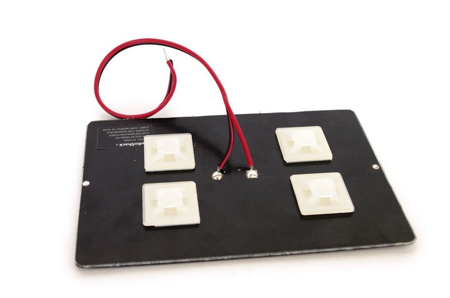
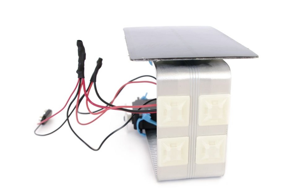
Place two pairs of clamp bases next to each other on the back of the solar panel. It is important that the channels of each pair are on the same line.
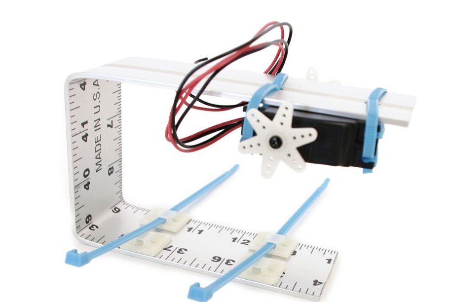
Step 7: More Reasons
Attach two more bases to the inside of the U-bar, to the side opposite the servos.
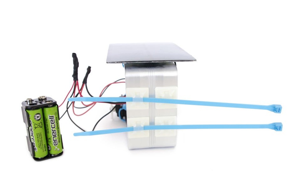
Step 8: Connection
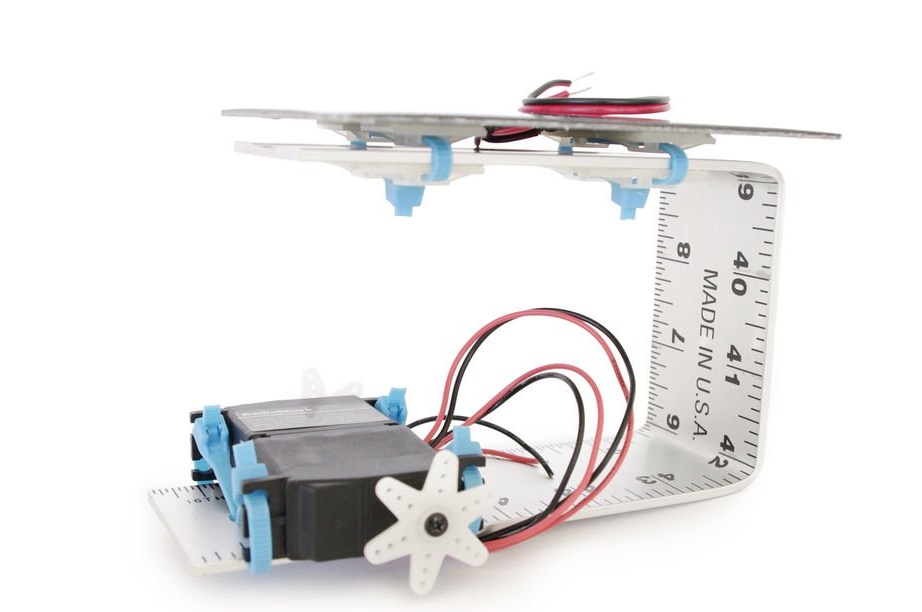
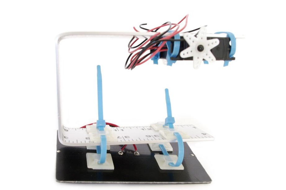
Attach the solar panel with clamps through fixed bases.
Step 9: Insert the Batteries
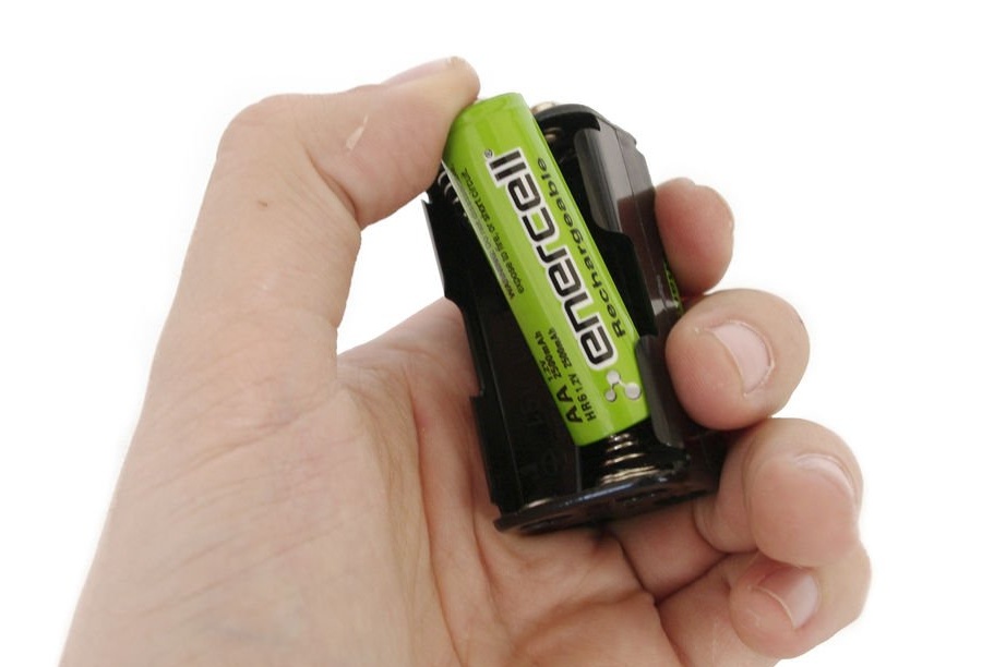
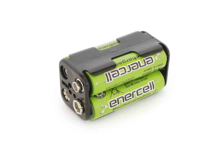
Insert the batteries into the battery pack.
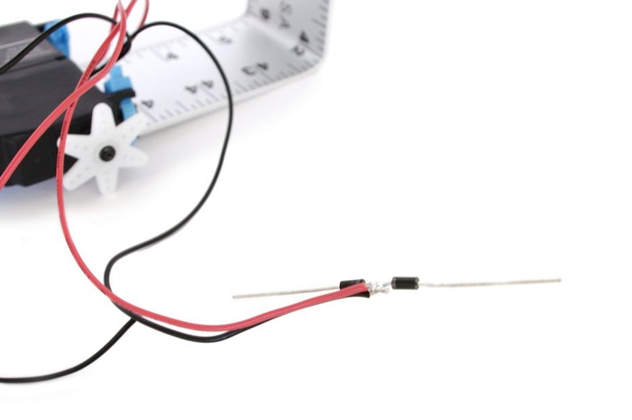
Step 10: Diodes
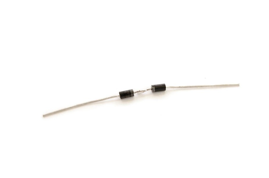
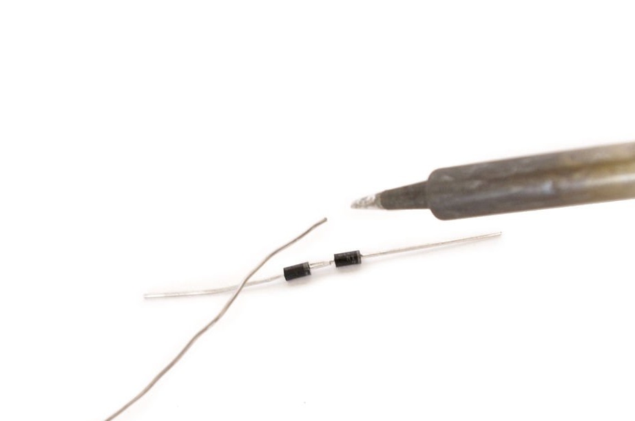
Solder the two diodes together with the cathodes (side of the diodes with the track).
Step 11: chain assembly
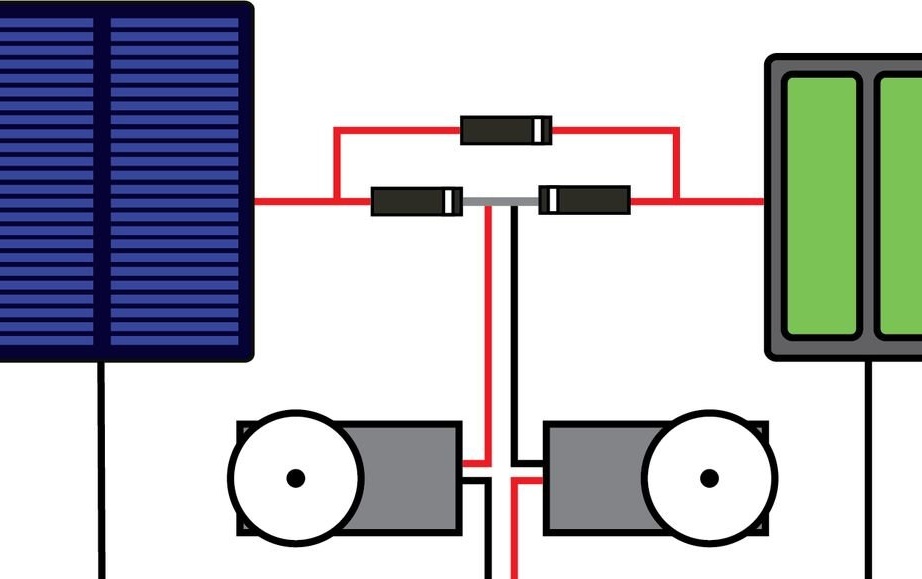
The circuit for this robot is based on David Cook's simple solar charging circuit. The circuit contains two Schottky diodes connected to the cathode-to-cathode, one diode connected to the solar panel and one of the batteries. This configuration allows you to be powered by both batteries and the solar panel, depending on the conditions.
Since the batteries are rechargeable, a third Schottky diode is connected directly to the battery compartment from the solar panel to charge the batteries from the sun.
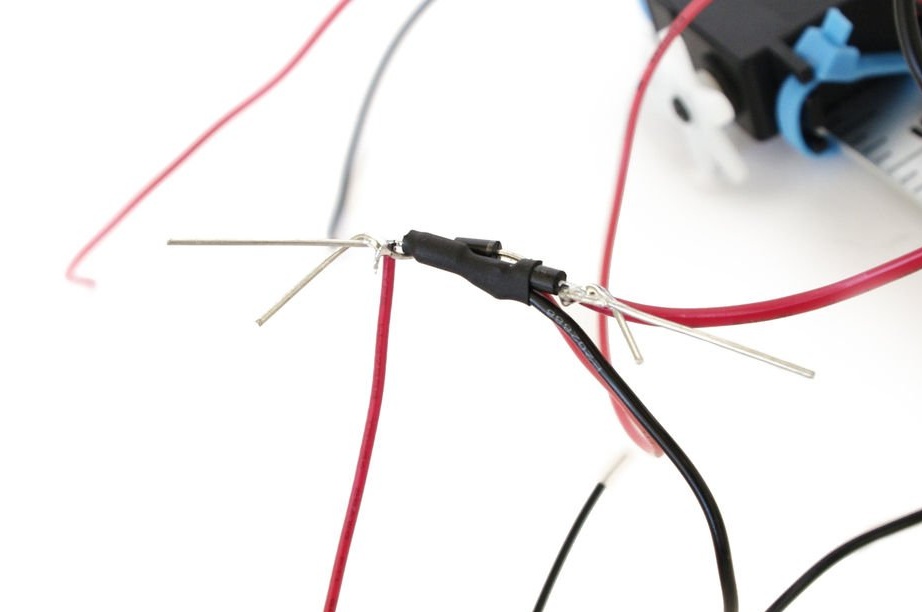
To connect it all, connect the red wire from one of the servos and the black wire from the other to the center point of the cathode connection.
Next, connect the red wire from the battery terminal to the anode of one of the Schottky diodes. Connect the red wire from the solar panel to the anode on another diode.
Now solder the anode of the third diode to the red wire that is connected to the solar panel, and the cathode to the red wire from the battery terminal.
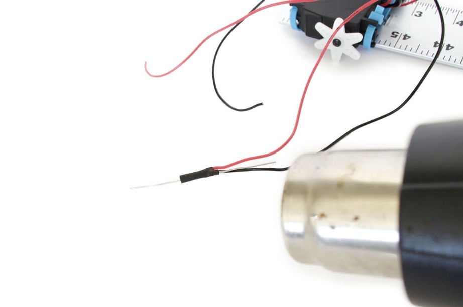
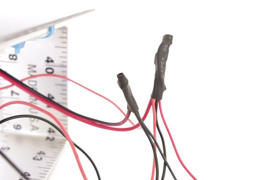
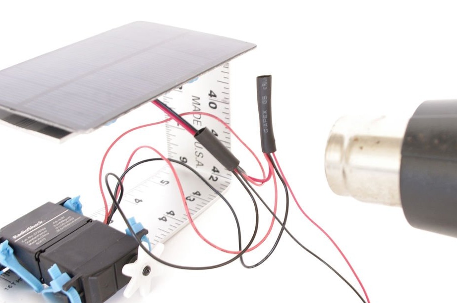
Wrap all wires with heat shrink tubing to protect the circuit from short circuits.
Step 12: Some More Wires
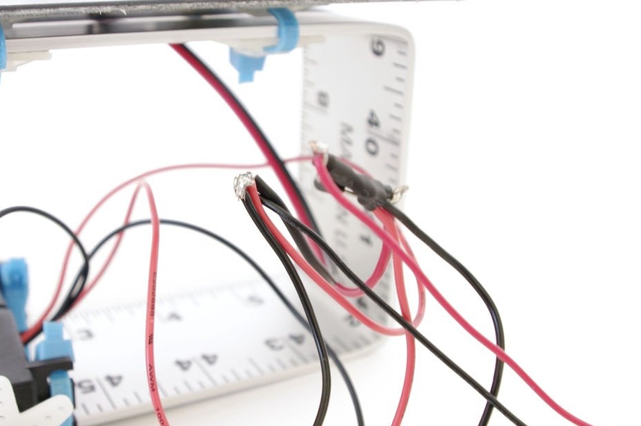
Solder together all the black wires and the remaining free red wires from the servos.
Get two soldered joints; one for power, and one for grounding. Wrap both of these joints with heat shrink tubing or electrical tape.
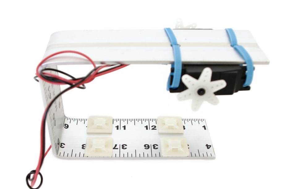
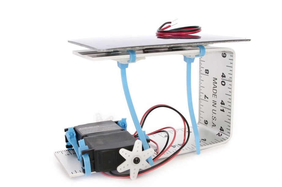
Step 13: And some more reasons for the clamps
Fasten two pairs of bases to the underside of the U-shaped curved ruler.
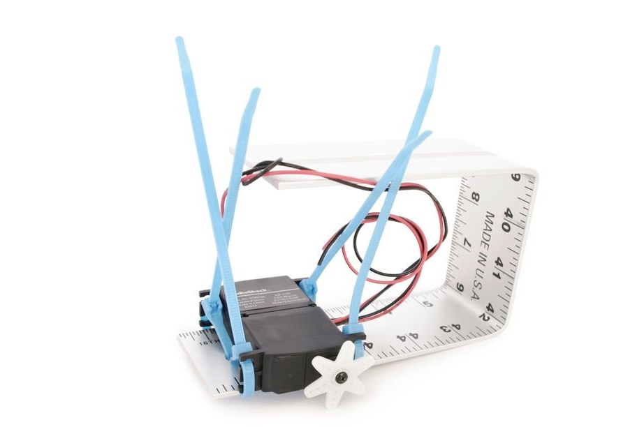
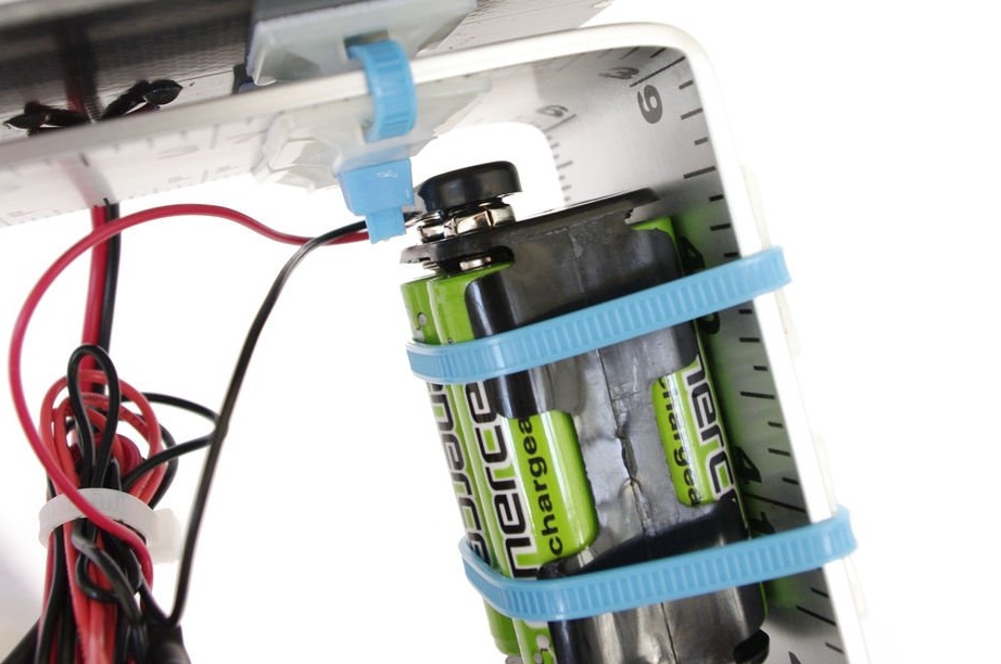
Step 14: Securing the Batteries
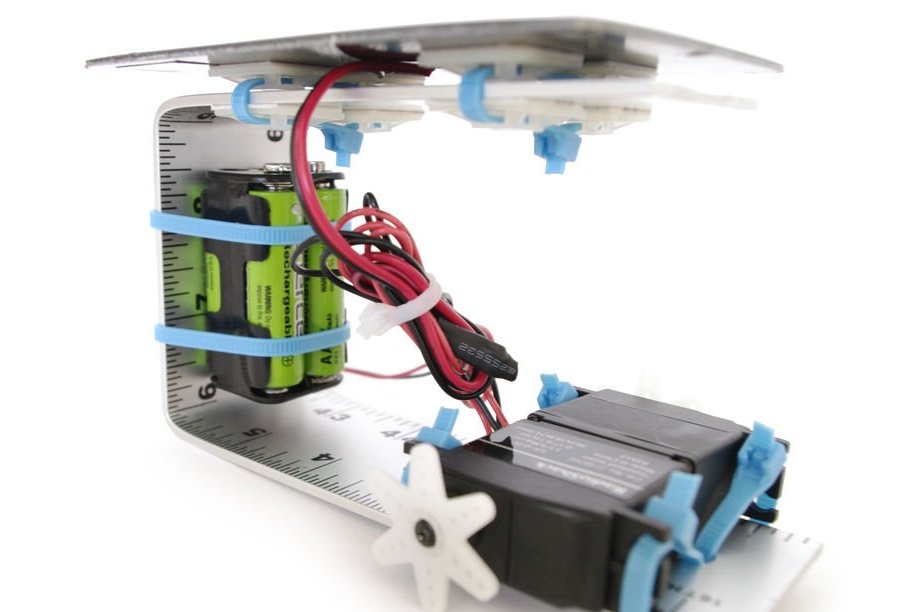
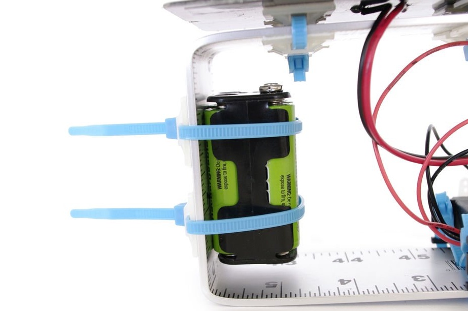
Secure the batteries with clamps inside the U-shaped ruler so that they sit firmly and motionless in place.
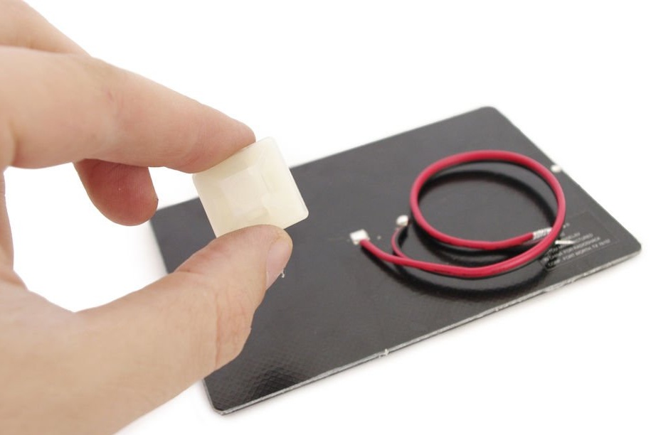
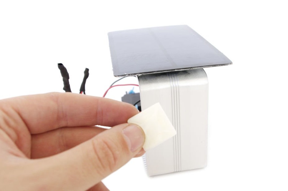
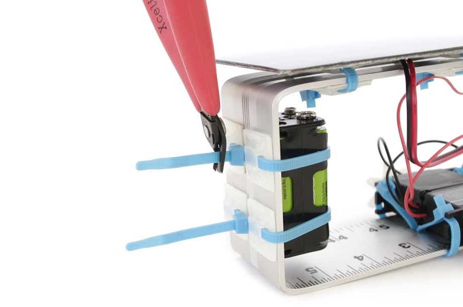
Step 15: Trimming
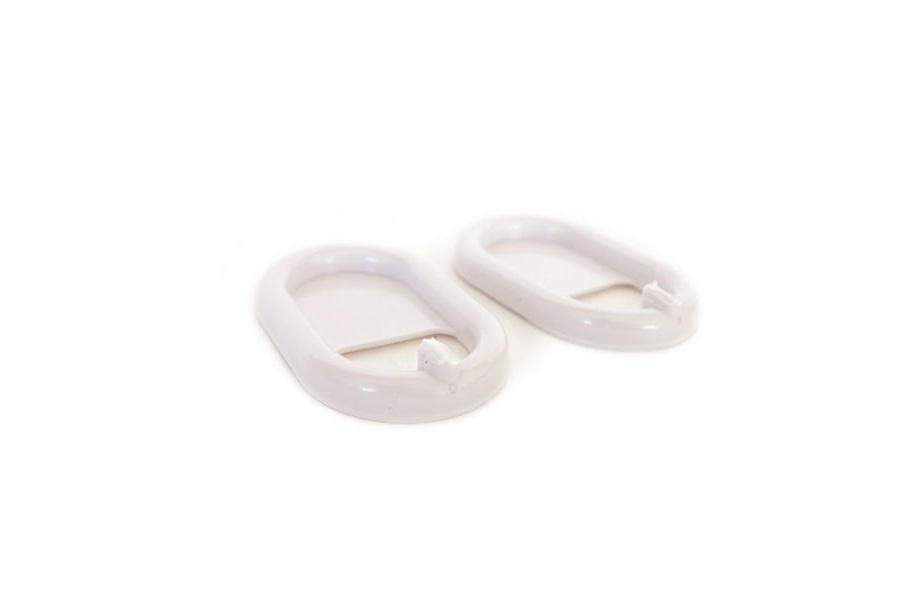

Cut the hooks on the plastic wall mounts.
Step 16: Wheels
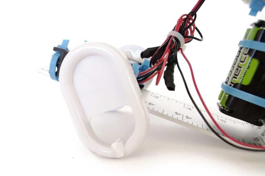
Glue the wall mounts to the outer gears of the servos (this will be something like wheels).
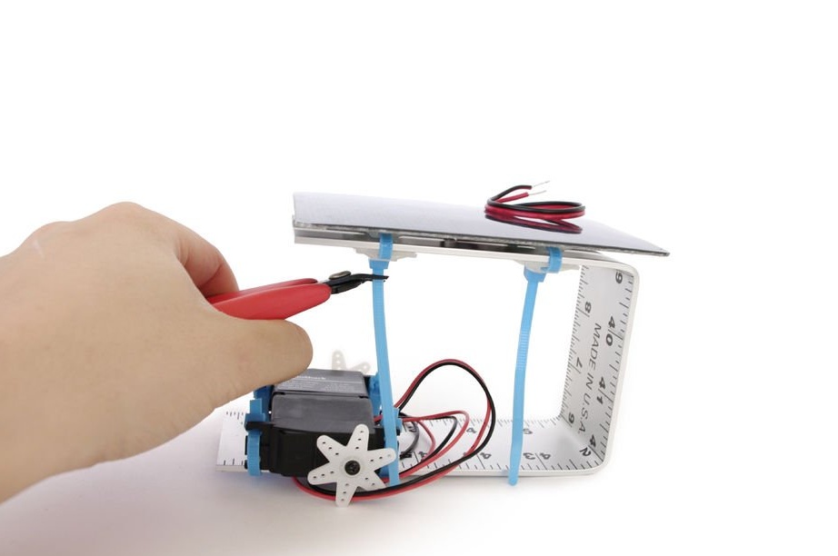
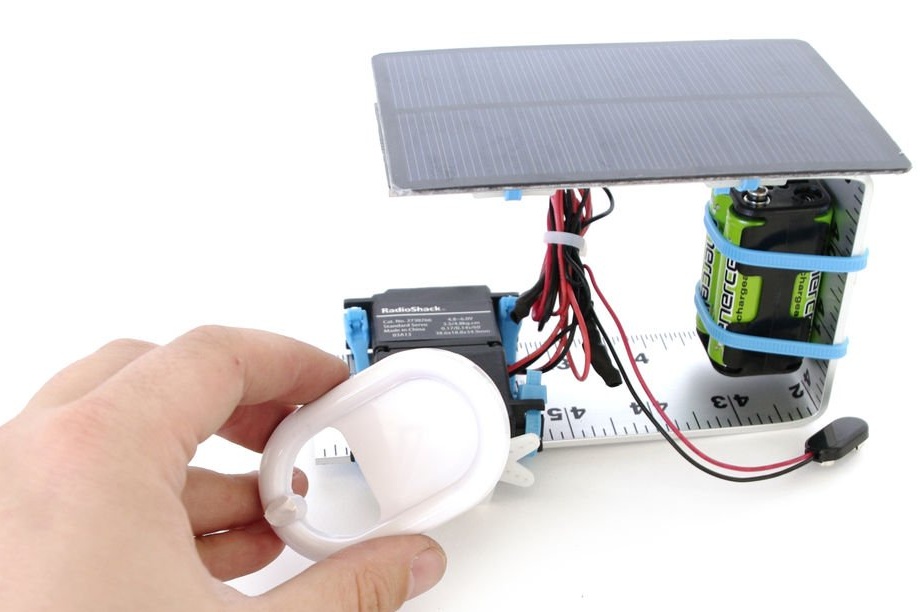
Step 17: Turn On!
Connect the lead to the battery pack and the robot will begin to move.