
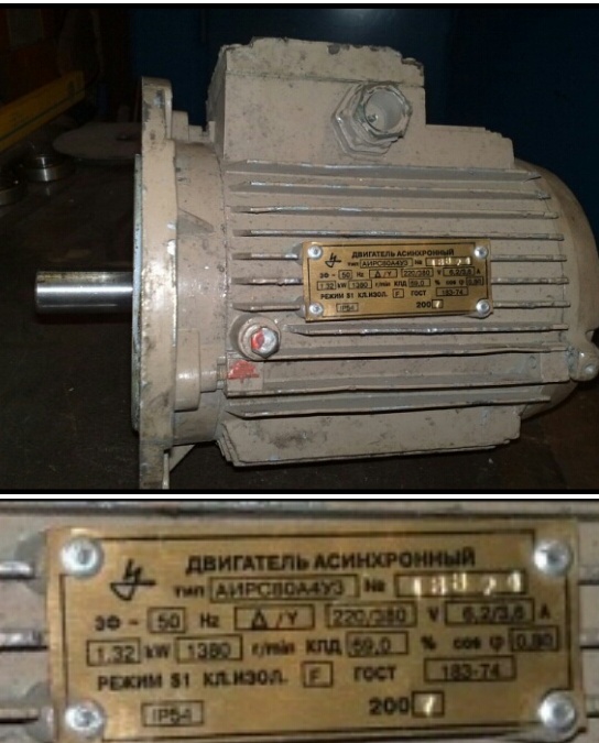
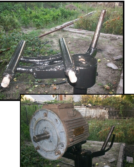
The alteration consists in the groove of the rotor for magnets, then the magnets are usually glued to the rotor using a template and filled with epoxy resin so as not to fly off. They also usually rewind the stator with a thicker wire to reduce too much voltage and increase the current strength. But this engine did not want to rewind and it was decided to leave everything as it is, only to remake the rotor with magnets. As a donor, a three-phase asynchronous motor with a power of 1.32 kW was found. Below is a photo of this electric motor.
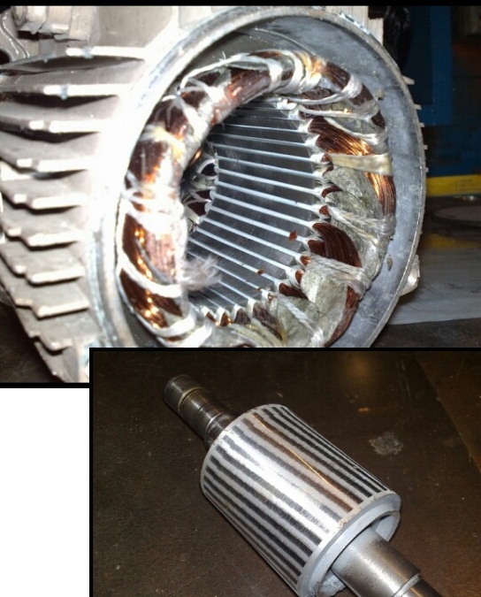
asynchronous motor conversion into a generator The rotor of the electric motor was machined on a lathe to the thickness of the magnets. This rotor does not use a metal sleeve, which is usually turned and put on the rotor under magnets. The sleeve is needed to enhance magnetic induction, through it the magnets close their fields feeding from under each other's bottom and the magnetic field does not dissipate, but everything goes to the stator. In this design, rather strong magnets of 7.6 * 6mm in size are used in the amount of 160 pcs., Which without a sleeve will provide good EMF.
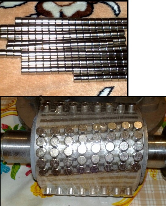
First, before the sticker on the magnets, the rotor was marked on four poles, and magnets were placed with a bevel. The motor was four-pole and since the stator was not rewound on the rotor, there should also be four magnetic poles. Each magnetic pole alternates, one pole conditionally "north", the second pole "south". Magnetic poles are made at intervals, so at the poles the magnets are grouped denser. The magnets, after being placed on the rotor, were wrapped with adhesive tape for fixation and coated with epoxy.
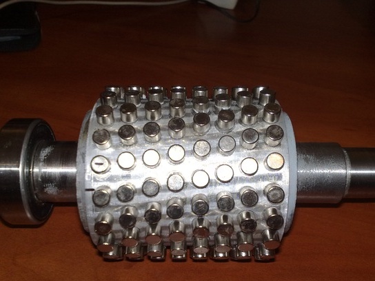
After assembly, sticking of the rotor was felt; sticking was felt during rotation of the shaft. It was decided to redo the rotor. The magnets were knocked down together with the epoxy resin and re-placed, but now they are more or less evenly installed throughout the rotor, below the photo of the rotor with magnets before pouring the epoxy resin. After pouring, the sticking decreased slightly and it was noticed that the voltage dropped slightly during rotation of the generator at the same revolutions and the current slightly increased.
After assembly, it was decided to twist the finished generator with a drill and connect something to it as a load.A 220 volt 60 watt bulb was connected, at 800-1000 rpm it burned at full heat. Also, to check what the generator is capable of, a 1-kW lamp was connected, it burned in full heat and did not master the drill more strongly to twist the generator.
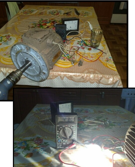
When idle at a maximum speed of 2800 rpm, the generator voltage was more than 400 volts. At about 800 rpm, the voltage is 160 volts. We also tried to connect a 500-watt boiler, after a minute of torsion, the water in the glass became hot. These are the tests the generator passed, which was made of an induction motor.
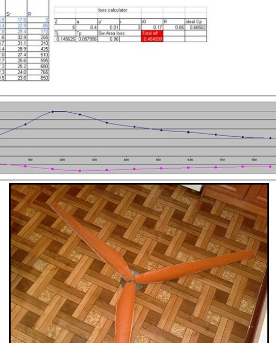
Then the turn came to the screw. The blades for the wind generator were cut from PVC pipe with a diameter of 160 mm. Below in the photo is the screw itself with a diameter of 1.7 m., And the calculated data on which the blades were made.
After that, a stand with a rotary axis was welded for the generator to mount the generator and tail. The design is made according to the scheme with the windhead removed from the wind by folding the tail, so the generator is offset from the center of the axis, and the pin behind is the king pin on which the tail is worn.
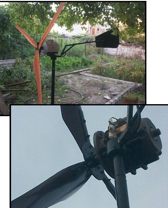
Here is a photo of the finished wind generator. The wind generator was installed on a nine-meter mast. The generator with wind power generated an open circuit voltage of up to 80 volts. They tried to connect ten tons of it to two kilowatts, after a while the ten became warm, which means the wind generator still has some power.
Then the controller for the wind generator was assembled and a battery for charging was connected through it. The charging was good enough current, the battery quickly rustled, as if it was being charged from a charger.
The data on the motor shaft said 220/380 volts of 6.2 / 3.6 A. means the generator resistance is 35.4 Ohm triangle / 105.5 Ohm star. If he charged a 12-volt battery according to the scheme of switching the phases of the generator into a triangle, which is most likely, then 80-12 / 35.4 = 1.9A. It turns out with a wind of 8-9 m / s, the charging current was about 1.9 A, and this is only 23 watts / h, yes a little, but maybe I was mistaken somewhere.
Such large losses are due to the high resistance of the generator, so the stator is usually rewound with a thicker wire to reduce the resistance of the generator, which affects the current strength, and the higher the resistance of the generator winding, the lower the current strength and higher voltage.