
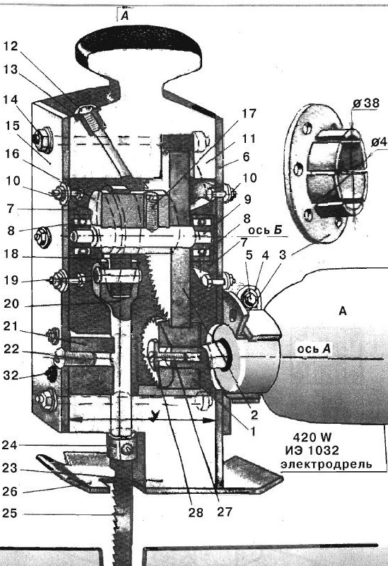
Fig. 1. Hand cross saw.
It is brought into engagement with the driven gear 2, after which the entire converter is pulled together with a bolt 5 on the neck of the drill with a clamp 4. Rotation from the spindle through gears 7 and 2 is transmitted to the eccentric 16, on which the swinging arm sits freely earring 18. It also converts the rotational movement of the eccentric 16 into the reciprocating movement of the working rod 20. The earring is connected to the rod by a finger 19. The reciprocating movement of the rod occurs along the guide 21. A saw 25 is fixed at the lower end of the rod, which works only in tension. Therefore, the teeth of the saw are directed up.
Before you begin to manufacture the converter, look for a pair of spur gears. Most likely, you will find the right pair in old appliances, gears, gearboxes. The diameter of the pinion gear 1 must not exceed the diameter of the neck of the drill. This is necessary so that the gear freely passes into the hole of the bearing flange 3. It will be better if the width of the pinion gear is at least 20 mm, which will ensure reliable engagement with the driven gear, since the first landing on the cone is associated with large longitudinal displacements. The height of the teeth of the gears should be 3-4 mm in order to ensure their best engagement, taking into account inaccuracies in assembly, drilling under bolts, loose fit on a drill and clamping with a clamp. To reduce the number of reciprocating movements of the rod 20 and increase the cutting force, the gear ratio should be taken equal to three. The gear ratio is determined by the ratio of the number of teeth of the driven gear to the number of gear teeth.
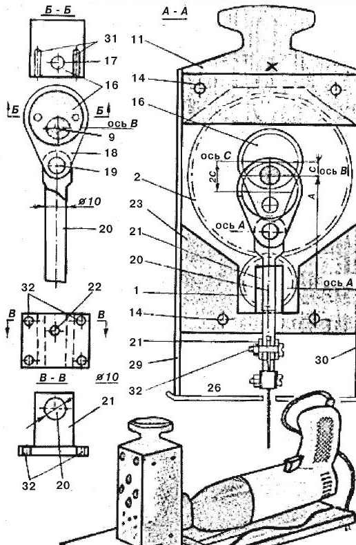
A matched pair of gears will determine the initial dimensions of the entire converter. If necessary, their internal holes will have to be customized for the drill cone and shaft 9. If the diameters of the gear holes are smaller than the diameters of the cone and shaft, you will have to bore them on a lathe. If the diameters are larger, it is necessary to grind the adapter sleeves (they are not indicated on the drawing). Having finished the work associated with the adjustment of gears, proceed to draw on graph paper the entire structure as a whole. An additional calculated value is the stroke of the saw. It can be taken equal to 10-14 mm.Therefore, you will know the distance between the axes A, B and C, as well as the dimensions of the eccentric 16. Having drawn the eccentric on the shaft 9, you will determine the diameter of the hole of the earring 18 swinging on the eccentric, the dimensions of the rod 20 and the guide 21. It must be noted that these parts work with sliding friction. Therefore, it is necessary to select blanks from such dissimilar metals as steel and bronze, steel and brass for their manufacture. According to the drawing, you will better see which one to choose a pair of ball bearings 8. The inner diameter of the bearings should not exceed 10 mm. According to their outer diameter, the dimensions of the flanges are determined 7. After all the dimensions have been clarified, proceed to the manufacture of the converter parts. Most of them are turned on a lathe. From oak beams, using exclusively joiner's chisels, cut the upper 11 and lower 23 parts of the case. Pay particular attention to the parallelism of the end planes and the equality of sizes X and Y (see Fig. 1 and 2).
[/ center]
Fig. 2. Hand cross saw.
These dimensions ensure assembly accuracy and machine reliability. Coat the inner surfaces of the bars with epoxy resin or oil-resistant varnish. Align the eccentric 16 with gear 2 on the common shaft 9 and drill two holes for the fixing pins 31. After pressing them into the eccentric body, open the pins on the gear. Then drill a hole and cut the thread for the fixing pin 17. After careful marking, drill holes on the drilling machine on the earring 18 and the rod 20, paying attention to the parallelism of the axes of the shaft 9 and the pin 19, the hole in the earring is blind and has a slip fit in the rod. Saw the guide out of the steel billet with a hacksaw. Drill holes in it for the mounting bolts and the rod. The stem hole must be machined with a reamer. From sheet duralumin with a thickness of 3-4 mm, cut the case covers, right 29 and left 30, rear 6 and front 15, as well as the support plate 26. Fold the front and back covers together, clamp with a clamp and drill holes for the tie bolts 14, fixing the bolts of the flanges 10 and the hole for the screw of the nipple 22 of the guide. After completing all the operations, proceed to the assembly of the machine. Screws and washers that are not indicated in the text, but indicated in the figure by numbers 12, 13, 24, 27, 28, 32, are taken ready-made, standard.