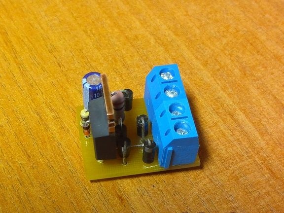
During the continuous burnout of incandescent lamps, including on the landing, several schemes for protecting incandescent lamps on the Internet were implemented. Their application gave a positive result - the lamps have to be changed much less frequently. However, not all implemented device circuits worked “as is” - during operation, it was necessary to select the optimal set of elements. In parallel, a search was made for other interesting schemes. As you know, the smooth inclusion of incandescent lamps increases their service life and eliminates inrush currents and interference in the network. In a device that implements this mode, it is convenient to use powerful field-effect switching transistors. Among them, you can choose high-voltage, with an operating voltage of at least 300 V at the drain and a channel resistance of not more than 1 Ohm.
Scheme of smooth inclusion of incandescent lamp No. 1

The author gives two schemes for the soft start of lamps. However, here I want to offer only a circuit with the optimal operating mode of the field effect transistor, which allows it to be used without a radiator with lamp power up to 250 watts. But you can study the first one - which is simpler because it is included in the gap of one of the wires. Here, at the end of charging the capacitor, the drain voltage will be approximately 4 ... 4.5 V, and the rest of the mains voltage will drop on the lamp. At the same time, a power proportional to the current consumed by the incandescent lamp will be released on the transistor. Therefore, at a current of more than 0.5 A (lamp power of 100 W or more), the transistor will have to be installed on the radiator. To significantly reduce the power dissipated by the transistor, the machine must be assembled according to the scheme below.
Scheme of smooth inclusion of incandescent lamp No. 2
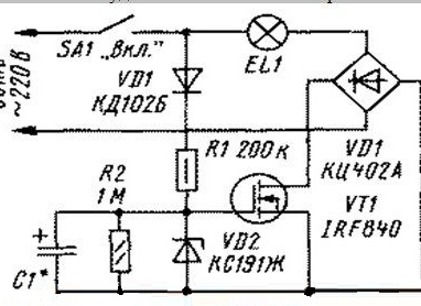
A diagram of a device that is connected in series with an incandescent lamp is shown in the figure. The field effect transistor is included in the diagonal of the diode bridge, so a ripple voltage is applied to it. At the initial moment, the transistor is closed and all the voltage drops on it, so the lamp does not light. Through the diode VD1 and the resistor R1, charging of the capacitor C1 begins.The voltage across the capacitor will not exceed 9.1 V, because it is limited by the Zener diode VD2. When the voltage on it reaches 9.1 V, the transistor will begin to open smoothly, the current will increase, and the voltage at the drain will decrease. This will cause the lamp to light up smoothly.
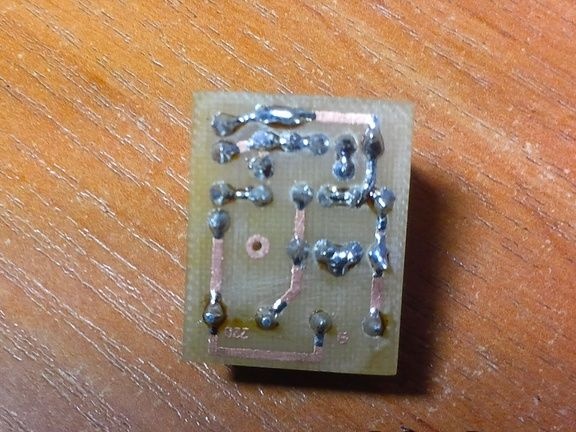
But it should be noted that the lamp will not start to light immediately, but some time after the circuit breaker contacts are closed, until the voltage across the capacitor reaches the specified value. The resistor R2 serves to discharge the capacitor C1 after turning off the lamp. The drain voltage will be negligible and at a current of 1 A will not exceed 0.85 V.
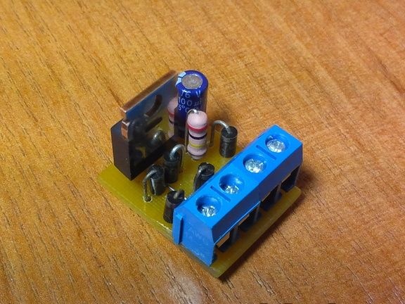
When assembling the device, 1N4007 diodes from used energy-saving lamps were used. A zener diode can be any low-power one with a stabilization voltage of 7 ... 12 V.
At hand was found BZX55-C11. Capacitors - K50-35 or similar imported, resistors - MLT, C2-33. The establishment of the device is reduced to the selection of a capacitor to obtain the desired ignition mode of the lamp. I used a 100 microfarad capacitor - the result was a pause from the moment of switching on to the moment of ignition of the lamp in 2 seconds.
Of no small importance is the absence of flickering of the lamp, as was observed during the implementation of other schemes.
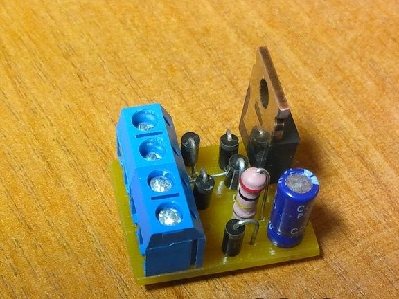
This device has been working for a long time and incandescent lamps have not yet been changed.
The author of the article and photo is Nikolai Kondratyev, Donetsk. Ukraine.
