» Electronics »Brovin Field Cache Field Effect Transistor

Brovin Field Cache Field Effect Transistor


Today we will look at some version of the Tesla Coil, called Browin Kacher. I will not go into history but I will say that the effect of quality (reactivity rocker) was discovered by a certain Brovin and patented the technology under his own name.

All welcome friends. I'll start my article with the word electricity. Electricity, as everyone knows, is fascinating; it can be both dangerous and useful. With electricity, you can move something; with electricity, you can light your way home. But today I will show how you can surprise with electricity.

Everyone has heard of the great genius Nicole Tesla and his Tesla Coil coils. At present, this device is gaining more attention than before. In appearance it is a complex device but in fact very simple. Today we will look at some version of the Tesla Coil, called Browin Kacher. I will not go into history but I will say that the effect of quality (reactivity rocker) was discovered by a certain Brovin and patented the technology under his own name.

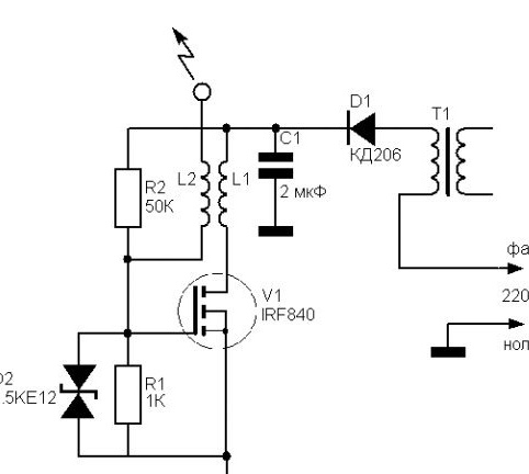
But what is this kacher? Kacher is a high-frequency generator of high voltage, it means the swing of reactive power through the generation of a transistor (mosfet).

So, to make it and get such a beautiful effect ...

We will need: copper wire with a diameter of 0.1-0.3 mm, a copper busbar with a diameter of 2 to 5 mm, a pipe with a diameter of 2 to 7 cm and a length of up to 30 cm, a pipe of a larger diameter than the first, a mosfet (irfp460, iff840 and other similar ones), a pair of 1 kΩ resistors and 50 kOhm, dual Zener diode 1.5KE12 or similar, non-polar capacitor 400 volts 0.5-4 microfarads, diode or diode bridge for current up to 10 amperes and voltage 800 volts, inductor from LDS or primary winding of the transformer (participates as a current limiter, the power must be at least 50 watts), a radiator for a mosfet with an area of ​​at least 50 squares

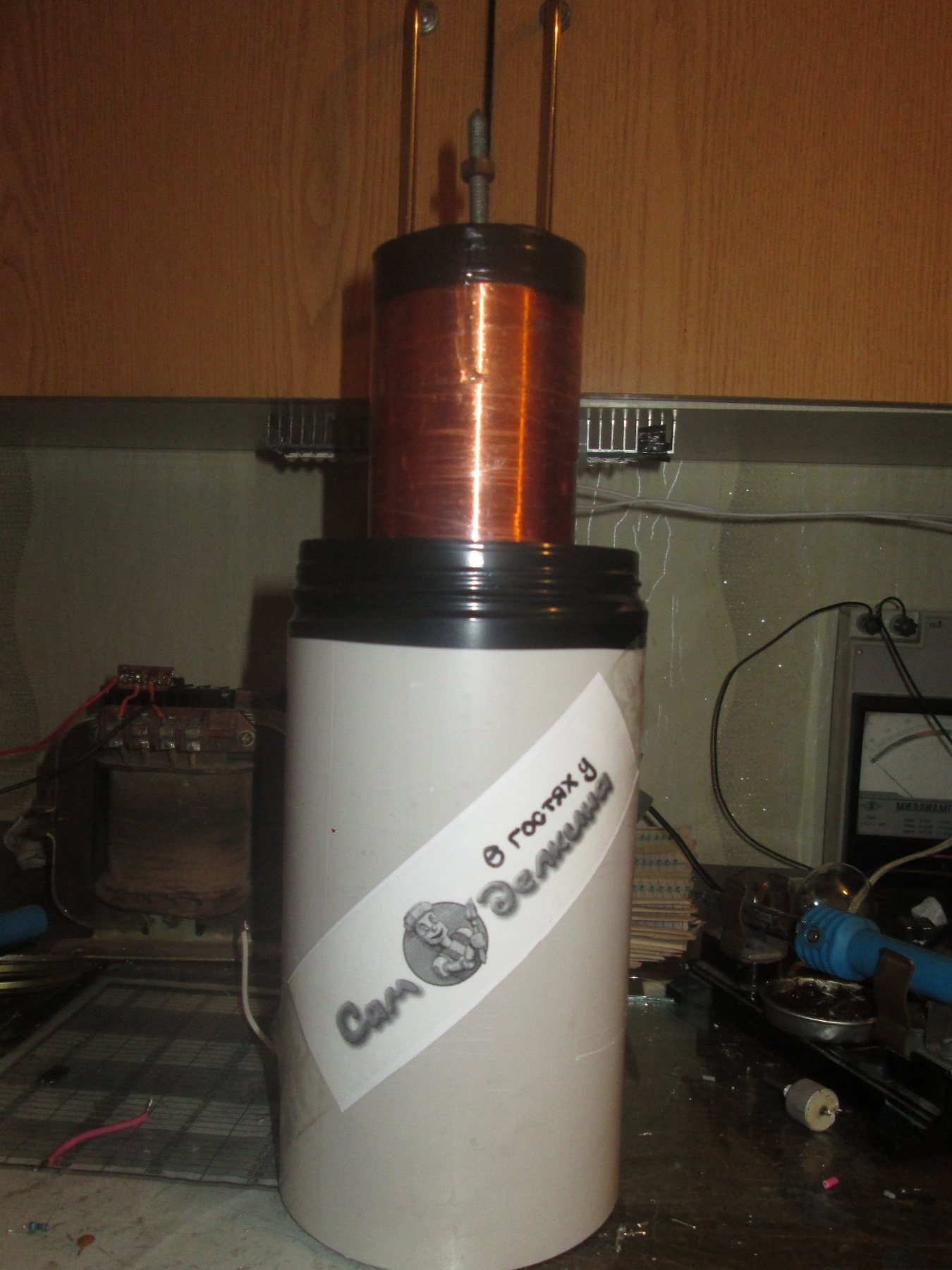
Here is such a sketch

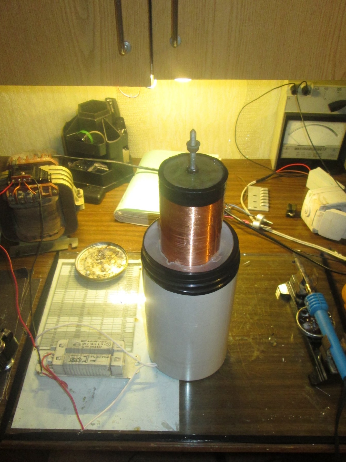
Everything needs to be prepared before assembly: the primary winding is wound in 1 layer with a thin wire onto a pipe of small diameter (800-1500 turns), after which it is impregnated with epoxy glue or other similar. The secondary winding is wound with a tire on a pipe of a larger diameter (5-9 turns) after which it is fixed with hot-melt adhesive or other similar.

After these manipulations, you are ready to build

Everything is going exactly according to the scheme (who does not know how to solder, learn, it will be necessary). When you finish soldering, it's time to check the device.This is done like this, add a 60-watt incandescent bulb to the circuit successively (if the circuit closes somewhere, the bulb will light up and nothing else will happen). If nothing works while the light is dim, this does not mean the assembly is incorrect, just swap the terminals of the primary winding and that’s it.
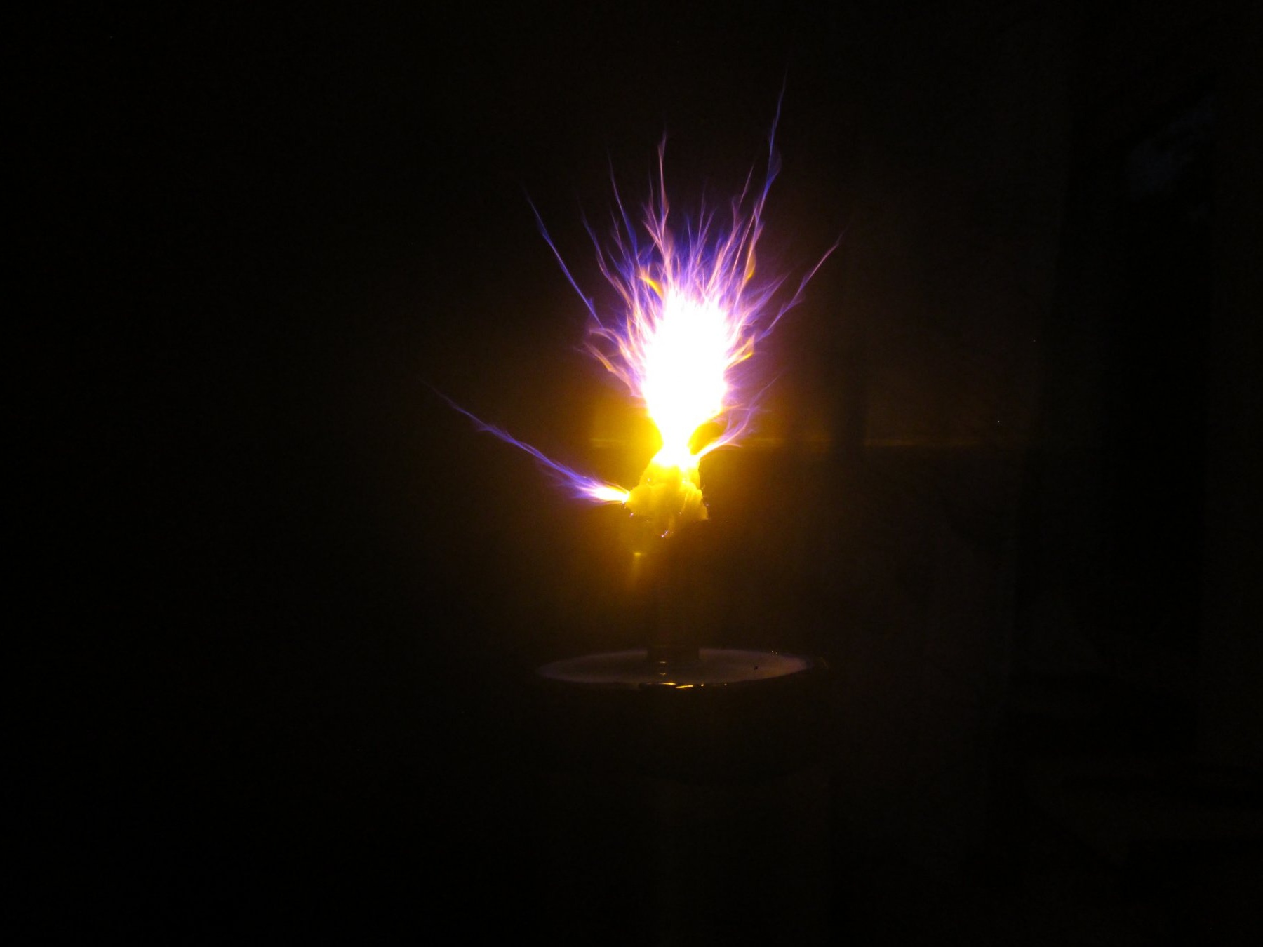
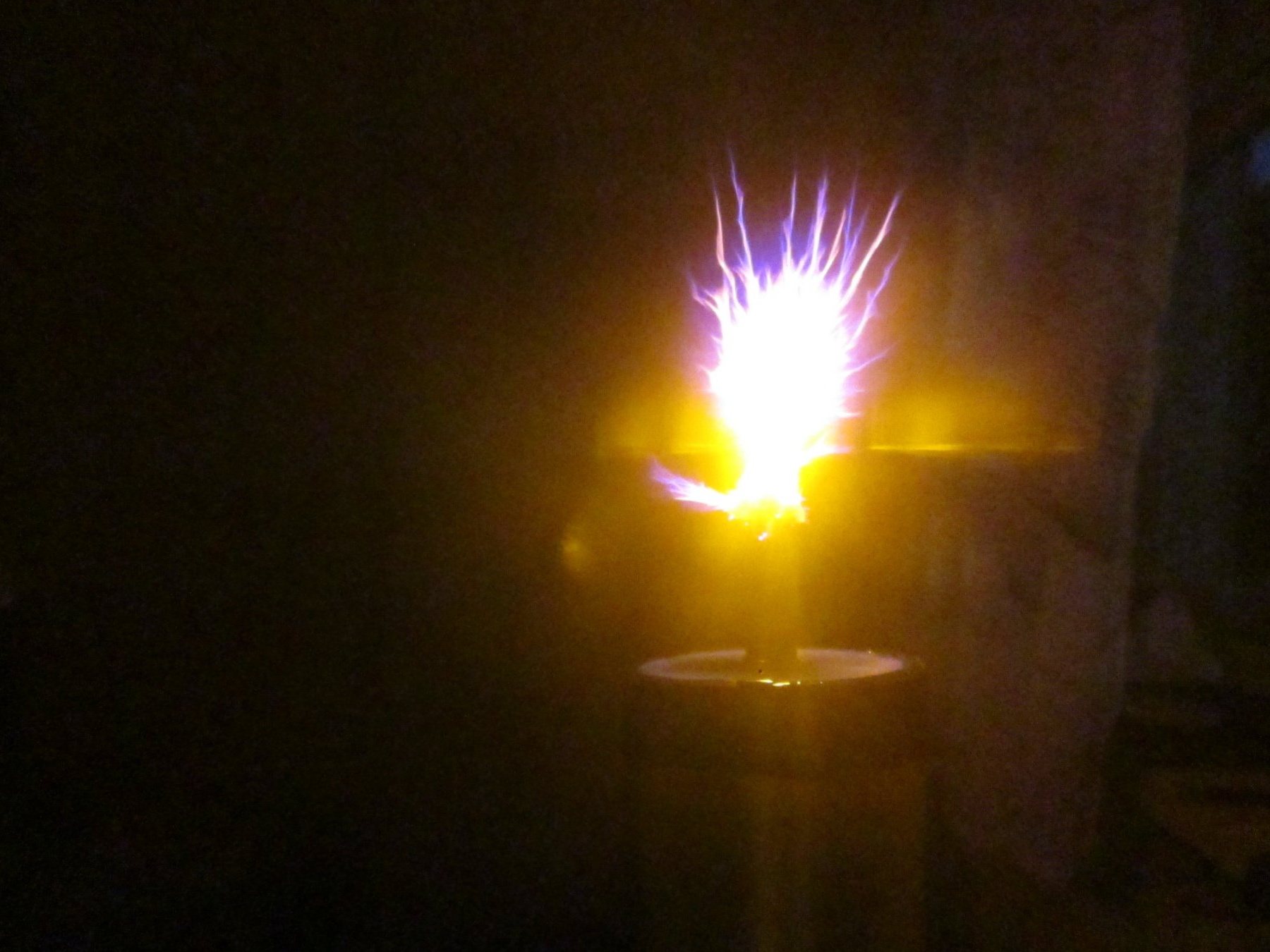
At the first improper start with the wrong scheme, expect: a loud babakh (the mosfet will burst), a lamp burning in full heat, the appearance of smoke or a burning smell. With the correct start-up and working scheme, expect: sparks will appear on the terminal (end of the secondary winding), the light will glow but not so brightly, the mosfet will confidently warm itself on the radiator (it should be so). After checking for operability, the bulb can be removed.

When all the tests have been successful, then it's time to think about the case, since without the case this rubbish that you have in the workplace will not look very kosher.

I use a pipe for the case, you can use the case from the computer’s power supply, everything is limited by your imagination.

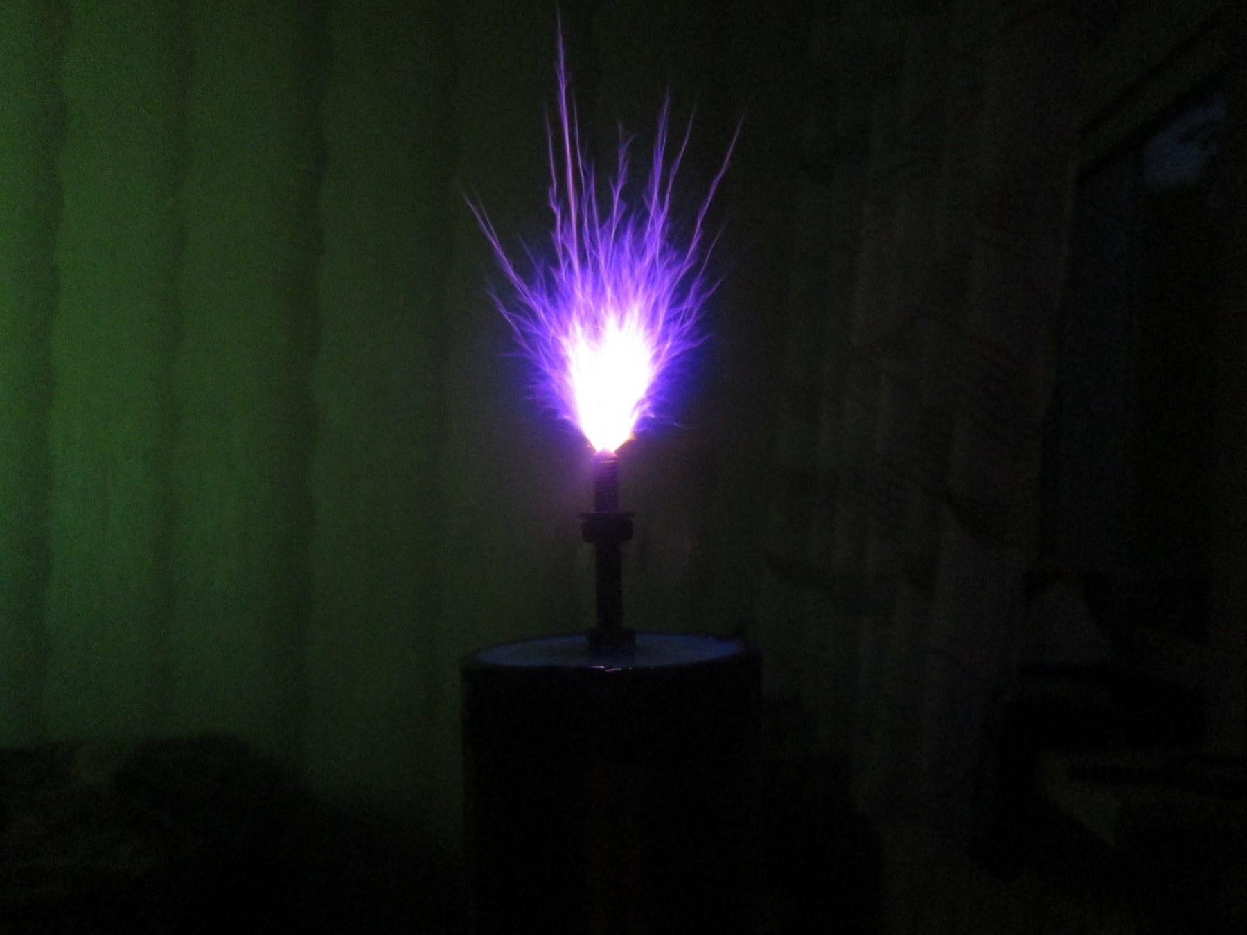
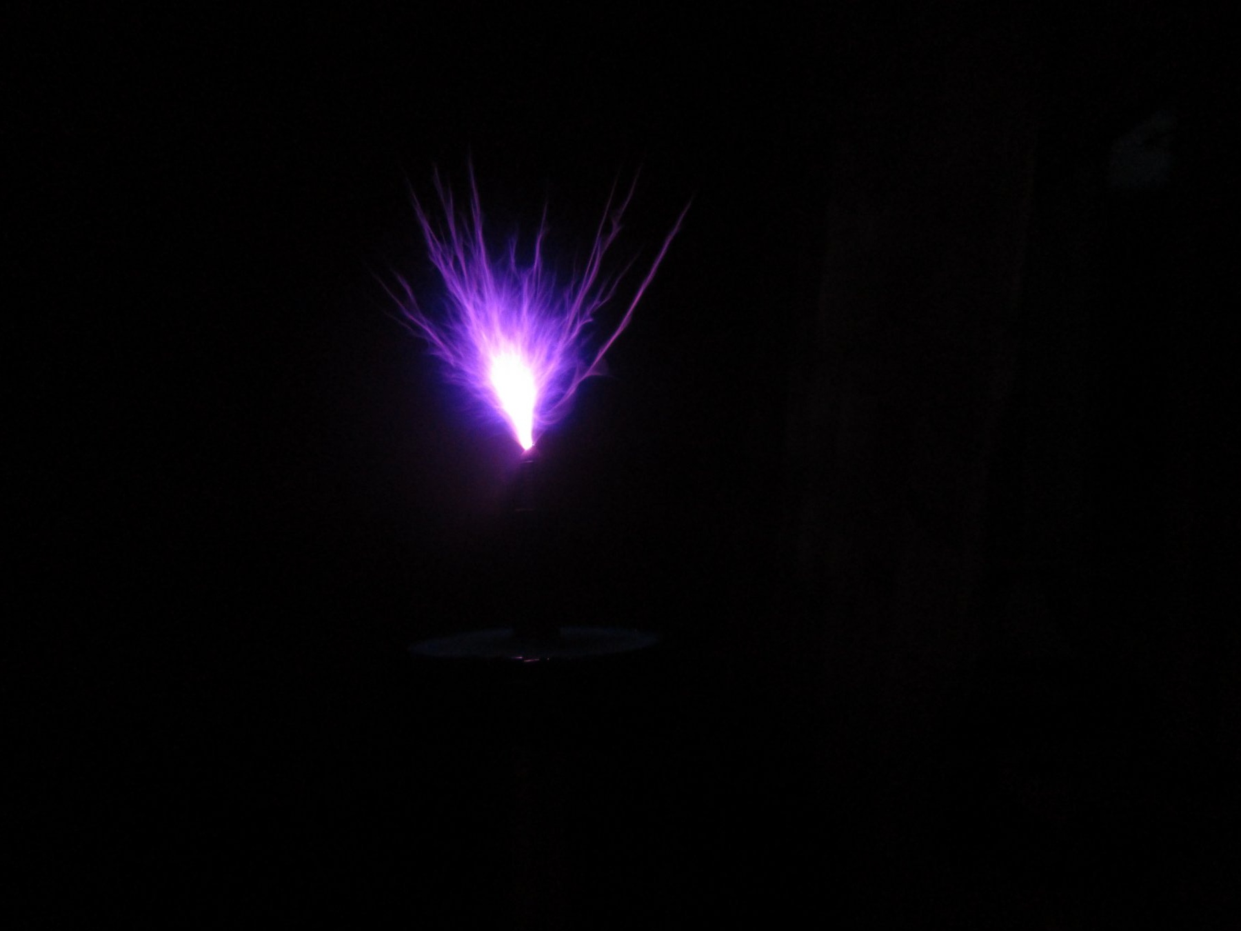
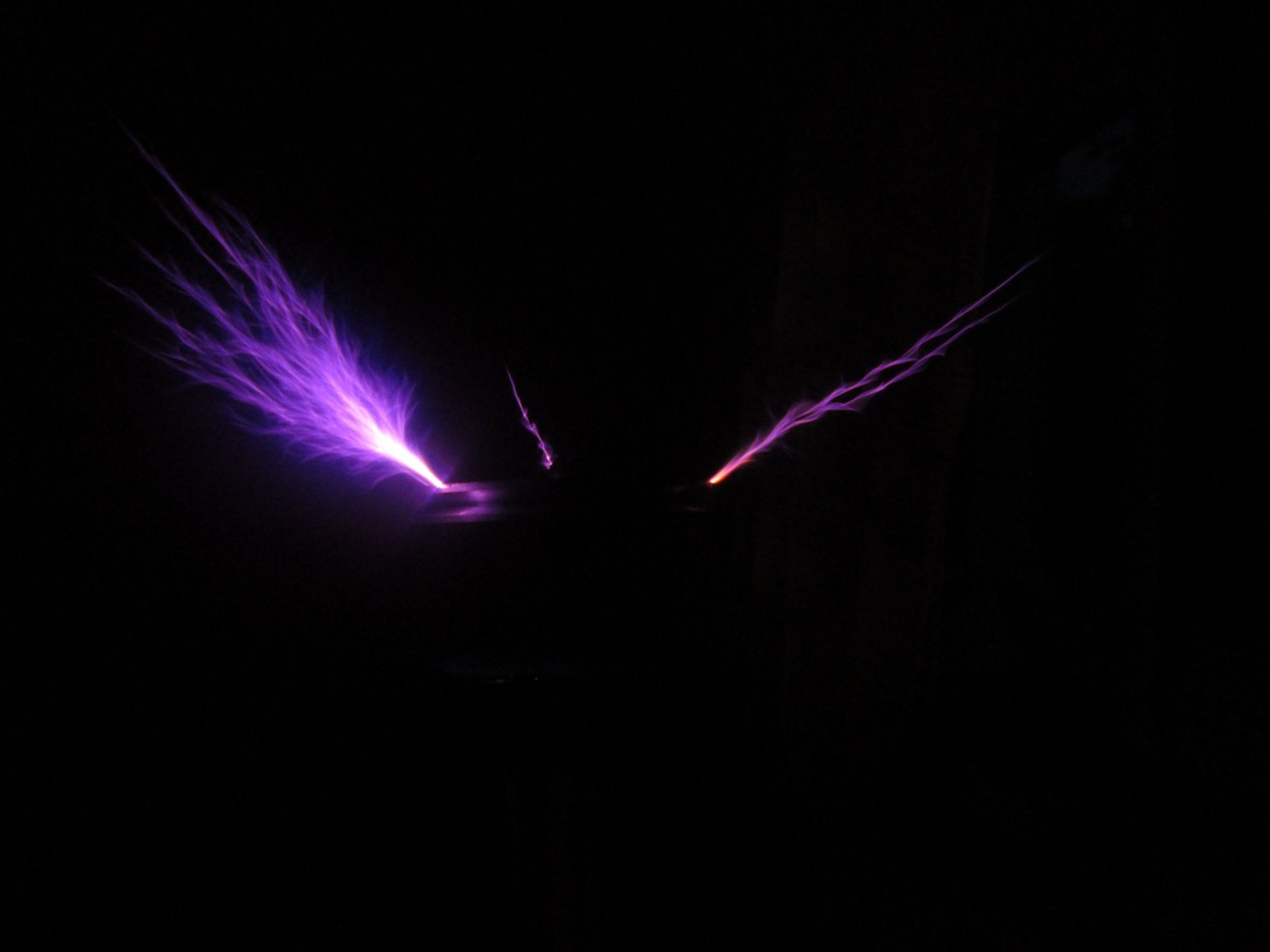
To complete the article, I will offer some beautiful photos of the received categories.


Device Repeatability.
Total Voters: 105
9.9
9.9
9.1

Add a comment

    • smilesmilesxaxaokdontknowyahoonea
      bossscratchfoolyesyes-yesaggressivesecret
      sorrydancedance2dance3pardonhelpdrinks
      stopfriendsgoodgoodgoodwhistleswoontongue
      smokeclappingcraydeclarederisivedon-t_mentiondownload
      heatirefullaugh1mdameetingmoskingnegative
      not_ipopcornpunishreadscarescaressearch
      tauntthank_youthisto_clueumnikacuteagree
      badbeeeblack_eyeblum3blushboastboredom
      censoredpleasantrysecret2threatenvictoryyusun_bespectacled
      shokrespektlolprevedwelcomekrutoyya_za
      ya_dobryihelperne_huliganne_othodifludbanclose
5 comments
Good circuit design on a field effect transistor.
Great opportunities in a wide range of frequencies and powers.
Ideal for experimentation and more.
Do you read what you write?
throttle from LDS or primary
everything is written here correctly, as a choke: 220VAC primary, and not secondary type Av + ​​Av & Bv + St & Dv & ...)
transformer winding (participates as a current limiter, power must be at least 50 watts)
the most common daylight bulb chokes are 36-40 watts, nominally on such a 110V choke (the remaining 110v on the lamp) while it limits (passes) the current at the level of 0.43 amperes, one cannot be connected to the outlet, two consecutively, 0.43 amperes will flow , reactively 80 watt (a quarter of a period the inductor consumes as a 160 watt iron, then gives all (almost, the efficiency is high, heating 5-10% loss of reactive (like that of a battery or capacitor) power into active (iron - winding resistance heating, irreversible) back to the network (or capacitor parallel but the plug in the lamps is inserted into good ones) through the counter, which was about to spin, but later changed his mind after receiving the reverse braking impulse of the reactive (return of goods and non-winding-up money account :-)) current, then all this is repeated on the next half-cycle of two quarters. the mass speed L = inductor inductance) with a positive half-wave begins when the mains voltage passes through zero, a negative sine voltage in the outlet starts to slow the inductor, and the current flows into the outlet through the sense counter I’m a neighbor’s iron, which at this time through your meter consumes and pays for your stored energy, while your meter changes its mind about spinning and charging. the same situation for all transformers at idle, wiring will be possible to heat even with amperes, but the counter will almost stand (the resistance of winding of the inductor and wires (if you have thin ones, and the idling of the "thick" welding transformer) is what is wasted on heating and, lost in the wiring, its heating will not return, will not pass back through the counter to be deducted without expenditure, as should all wired be superconducting and not aluminum or copper thin.

at the same time, few are aware that from a 12-volt battery, any sufficiently-volt (not 3.3V * 100.0 microfarads, but say a 16V * ... microfarad capacitor) capacitor through a resistor, or directly (which is generally somewhat wrong, like refueling a vacuum vase with tap water from a city 4-atmospheric pressure water supply, rarely connected to a thick pipe without taps ... a water hammer is provided, but usually there is a resistor (tap with a micro-hole) and the vase will survive, or it is strong as the leads and plates of electrolytic capacitors, sparking when instantaneous (or rather not og anichennom) discharge current fault screwdriver or (almost the same for the capacitor wiring) "RS" -charge (kOe on bus 12B the battery is charged to 12 volts
without resistor
Well, it is clear that one way or another, 12V will be on the capacitor, and so through the inductor and diode in series, the capacitor (ideally) will be charged up to 24V, because unlike a resistor spending too much on heating, the inductor stores energy at the current speed, at first it quickly accelerates from the "extra" 12v 11v 10v to the capacitor 1A 2A ... under the "end" of the charge at 12v the capacitor has 0V on the inductor but it it is accelerated to a current corresponding to the tripled energy of the capacitor, and braking, at first reluctantly, and at the end (closer to -12 volts on it and 24V on the capacitor) it is already faster to zero current when the diode “fixes the result” like a ratchet of a hand brake to which throttle weight was welded, and the bruiser hurriedly he pulled the mark 10cm up, at any cost, and overdid it, jumping out of the car, while there a weight up to 20 cm clicked the handbrake.

therefore, on the capacitor in the circuit shown here, if it does not start (without load), it may well be 620 volts - twice the peak voltage of 220VAC sine wave (220V rms (power on the iron is equivalent to a constant voltage of 220VDC) * root of two = 310v peak, peak of the sine wave 220VAC 220VAC * 1.41 = 310Vmax & -310Vmin (anti max)) with an iron equivalent to a constant voltage of 220VDC) * root of two = 310v peak, peak of a sine wave 220VAC 220VAC * 1.41 = 310Vmax & -310Vmin (anti max))
primary the winding is wound in 1 layer with a thin wire onto a pipe of small diameter (800-1500 turns), after which it is impregnated with epoxy glue or the like. Secondary the winding is wound with a tire on a pipe of a larger diameter (5-9 turns) after which it is fixed with hot-melt adhesive or other similar.
the primary - the one to which we feed, 5–9 turns of the “low voltage” winding of the Tesla coil, the secondary - where the result is ringing at the resonant frequency, leading to the buildup to high voltage of the multi-turn secondary and the length of the “swing” of the oscillatory circuit of the secondary of the high voltage and its capacity + ball at the top, many people sculpt if there are a lot of transistors and they sit idle with their muscles cold, because Nowhere to go at the exit of power.

at least it’s better to protect the IRF840 transistor from overvoltage and the source gate along the circuit (as in the diagram), usually I use a 27 volt varistor in pulsers and UMF Class D (but here I’m not sure that a varistor no worse than a diode can parallel with an ultrafast diode - the very thing will happen, or maybe the varistor itself will go off with a bang, and it’s better unidirectional like the author has in the circuit), a sufficiently powerful zener diode 12-30v is suitable here, a bi-directional TVS diode should be shunted with an ultrafast diode to the side, it's just not clear according to the scheme in which one-way was supposed to be directly turned on Injected TVS diode recommended by circuit.
I also recommend putting on the drain-source of the IRF840 transistor a voltage-limiting drain-source voltage below 500 volts acceptable for this fieldman, I set varistors or bidirectional TVS diodes in 380v or 470-volt pulse circuits, as well !!! important! complemented the cheap reverse current diode built into the IRF840, with a powerful 100v 10A (normal) -100A (peak) ultrafast diode (not ultrafasts have time to close at the fronts, a meander even at 20kHz receives a surge at the front or a blurry front - depending on the type of load, I burned 38 pieces of IRF-840 in a row for two days of experiments, but 39 and 40 of those bought at 20 rubles per piece 40 pieces of IRF840 at God's will withstood all the following very careful moves and shunted by varistors 18-27V ZI, 380-470v SI, ultrafast IS 1000v 10A ,supply to the gate through a 10-ohm resistor (there will directly be a ringing of HF at the edges of the gate having a decent capacity coupled with a 4A peak driver current and circuit board wires that knocks the transistor out faster than a smoothed 10 ohm (in the field pole gate charge circuit) is collected when loads increase to limit) buildup from IR2153 or TL494 + IR2123 half-bridge driver in my opinion (UMZCH class D-shim)
This is how 200W 20-25KHz on TVS-110 worked, with 43 primary coils with a thick 1mm wire, on one side and a high-voltage standard cable on the other, at 30-40KHz the МН2000 core is heated and the main high-voltage coil burns out overheating in a day, 40KHz already requires fluoroplastic insulation and is thicker Apparently, the lavsan does not roll in any way, the loss tangent is high - it heats up like a microwave, and gradually burns through the interlayer insulation of high-voltage coils with it), it turned out to rectify 15 kW 200 watts was not a television multiplier (which is weak by 11 kHz ) and not microwave diodes (which at 50Hz and do not have enough time for 5-10% of the period to lock at 20kHz meander), but only 20 garlands of ultrafast 1000v 10A ultrafast that work perfectly, do not heat up and do not burn, allowing the high-voltage capacitors to charge after them not up to 4 kV and that’s all (the microwave diode is hot at the same time), but up to 15 kV as it should, and then with a current of tens of milliamps on GP-3 lamps 4 pieces to disassemble spend it. I couldn’t do more than 200 watts, the fuel assembly is warming up or the full-time television high-voltage burns, they say you can squeeze 600 watts, I saw examples, I don’t remember what they screwed up, the core, transistors (2 pcs) or they shook their high-voltage
UMZCH on two IRF840s with these protections when powered by + -85 volt half-bridge, these poleviks remained a little warm, right up to combustion, which, while increasing the power of four speakers in the 4-ohm disco speakers, reached 1200 watts of bass, they lived for several seconds, bursting when someone clicked on the mixer in addition to the drum and bass, which surprised the survivability of two IRF840s, barely warm, this thing ...
38 transistors burned out while the varistors and the diode and resistor were thought up to configure, as well as at frequencies of 40 kHz which are easy for them but the fuel assembly broke through and were knocked out
dilshodase
Hello! Explain how you wound the primary winding? You have a diode on the TVS circuit, not a zener diode. Is there any zener diode suitable for 12 volts or not, otherwise I can’t find one?

We advise you to read:

Hand it for the smartphone ...