
Power amplifier MF1
1. Excellent sound and clear bass;
2. Reliability, even in extreme conditions;
3.Availability in repetition, does not have scarce details;
4.Excellent PCB topology.
I have long wanted to assemble a good and high-quality audio power amplifier (UMZCH), I searched for a long time on different sites and forums, but could not decide. Some amplifiers were simple, but the sound they had left much to be desired, the second ones were difficult to set up, and the roads were expensive to perform. I tried to assemble a couple of amplifiers, both simple and complex, anyway I was not satisfied with the sound (maybe my crooked hands are to blame
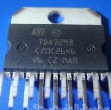
 , although I'm a little friends with radio electronics). But then I came across a link to UMZCH called MF1 (MadFeedback1)whose heart was the TDA7294 chip (TDA7293).
I looked at the diagram, nothing complicated in the assembly, the components are not expensive, and scrubbed through the guts, I found all the details except the microcircuit. It was decided to collect and check !!! The next day, a microcircuit was purchased, and not just one but 2 (TDA7294 and TDA7293) in order to check their sounds, because they have slightly different parameters on the datasheet and on the forums this also confirms that their sounds are slightly different. He walked around for a couple of hours, gathering his courage and finally got to work!
For half an hour, the board was etched, tinned and drilled. Even somewhere in an hour all the components were soldered, I had to tinker a bit with the capacitors, since mine were a bit larger than the printed circuit board could provide me with space. I also had to tinker with the radiator. It was decided to use a smaller radiator, but with a cooler, since a lot of heat is generated during operation, I did not want to pile up a large radiator, but I could do with a smaller one, but with forced cooling. After assembling this miracle, I ran into another problem, it has two polar power supply, that is, + 40V 0 -40V. Immediately I ran to my zashashnik and, to my deepest regret, I did not find a transformer suitable for these parameters.
Well, what to do, I went to the radio store for a transformer, the prices just upset me, for a suitable transformer we broke the price in the region of 50-60 dollars. He arrived home and began to think what to do, because the amplifier is already ready, and the fighting spirit. I climbed into my favorite Google and found a switching power supply circuit for an amplifier with two polar power supplies.How I collected it is another separate story: fellow :. A week later, when I tried several circuits of power supplies and settled on one that satisfied me with its reliability and rather complicated assembly, I carried out my first launch of the amplifier !!!
But here I was disappointed with the noise in the speakers, although the website and the forums said that everything was just fine and no noise. I started to sin on the power supply, since a switching power supply with poor filtering can well give interference to the amplifier. I double-checked everything and couldn’t understand why, but in the end I found the answer on the forum that the whole problem was in the cable going from the computer to the amplifier (I had a cheap Chinese wire).
Found a new three-wire wire with a screen, soldered and voila, silence. At first, I was even scared that something was burning, but listening to the speakers, I heard a faint hiss. The first run of the song almost stunned me, I forgot to turn down the volume on the computer, and I have not yet set the volume control on the amplifier. Having removed the volume to 5 percent, I tried again, because I was delighted to say nothing.
The amplifier really played cleanly, all transitions between parts and no dips or wheezing were heard, with an increase in volume, a clear and juicy bass was clearly heard. In conclusion, I can say that I was satisfied with this amplifier and I can recommend it for assembly. Below I will provide some features that must be followed during the assembly so that there are no questions like why it doesn’t work for me or it works but it doesn’t. With proper assembly and working components, the amplifier does not need to be tuned !!!
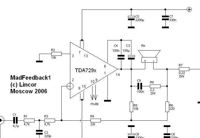
Amplifier circuit itself
[center]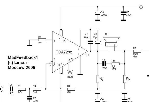
[center]
Printed circuit board and the arrangement of elements on it
[center]
[center]
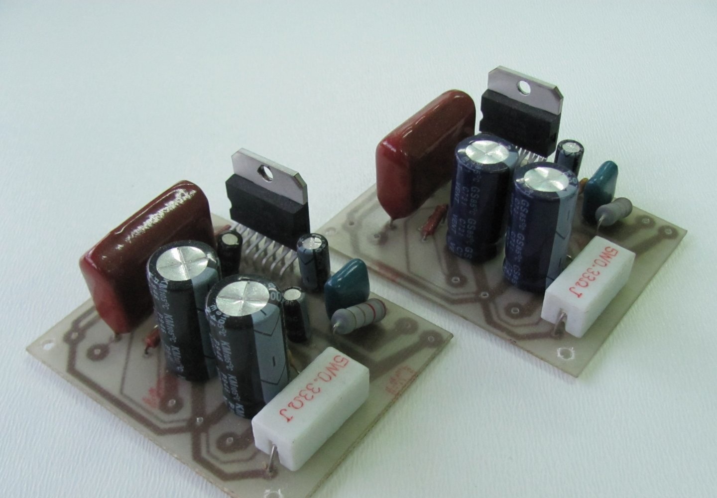
Board Assembly
[center]
The characteristics of the amplifier when working on a 4ohm load (IC TDA7294):
Operating frequency range, Hz 20-20 000
Supply voltage @ 4 Ohms, V ± 30
Supply voltage @ 8 Ohms, V ± 40
Rated input voltage, V 0.6 rms
Rated output power, W 73 rms
Input impedance, kOhm 9.4
THD at 70W, not more than,% 0.3*
THD at 60W, not more than,% 0.01*
* manufacturer specifications
Details:
Resistors: All resistors, except R7 and R8, are carbon or metal film resistors at 0.125-0.25 W (it is advisable to take resistors more precisely, where the spread varies + -1%).
[center]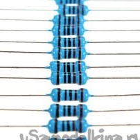
approximate view
Resistor R7 - 5W wire resistor. White SQP resistors in a ceramic case are recommended.
R8 -, coal, wire or metal film 2W.
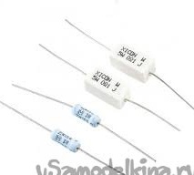
approximate view
Capacitors: C1 - film, of the most affordable quality, mylar or polypropylene (MKT or MKP) for a minimum voltage (usually 50V). In the absence of access to expensive thoroughbred components, the K73-17 at 63V will give a satisfactory result. C4 C7 C8 C9 film type K73-17 at 63V.
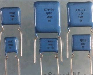
approximate view
C2 - ceramic disk or any other type, for example K10-17B.
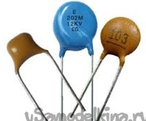
approximate view
C3 - electrolyte of the highest quality available at a voltage of at least 35V,
C5 C6 - electrolytic, preferably imported high-quality, for a voltage of at least 50V and preferably at 60V.
C11 C12 - any electrolytic voltage of at least 25V.
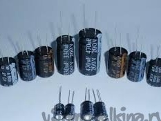
approximate view
Diodes: D1 - any zener diode at 12..15V with a power of at least 0.5W.
Amplifier chip - any of the TDA729x line (7296..7293). In case of using TDA7293, it is necessary to bite or bend and do not solder the 5 leg. In general, just in case, this applies to all microchips of the line.
ATTENTION! Power amplifier two polar. Both output terminals of the amplifier are “hot”, none of them are grounded, because the speaker system is also a feedback link. The speaker is switched on between OUT + and OUT-. You should also ground the heatsink of the microcircuit. This is a prerequisite for stable operation of the chip. She is afraid of statics - it must be isolated from the radiator, and the radiator must be grounded to the midpoint of the power supply. That is, there is a radiator, a layer of thermal paste, then a mica pad, a layer of thermal paste, a microcircuit. The chip must be screwed to the radiator through a dielectric washer. We also fasten the wire to the radiator and connect it to the board at the GND point
P.S: I personally liked the sound of the TDA7293 chip, the bass is stronger and its reliability seems to be better.If there is a possibility, instead of large 2200x63v electrolytes, it is possible to supply 3300x63v, then it will be even better, the main thing is that they fit on the board. And on nutrition, it is advisable to use + -35V, although it is written that it works at + -40V, but this is its limit, with a strong power surge it can fail!
I wish everyone success in the assembly and a pleasant listening!