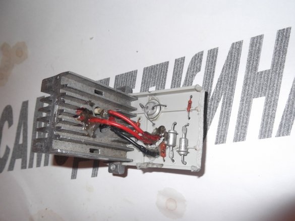
A few days ago I purchased a small drill for drilling printed circuit boards, but unfortunately it rotates at a constant frequency, but I would like to regulate the speed of this drill.
Rummaged on the Internet, found a transistor voltage regulator circuit for a “fun power supply” (Author: Yunost TV Channel)
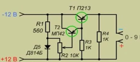
But -12 and +12 (if you take these conclusions from a computer power supply) in total will give 24V, and at the output of our regulator we have only 9V. Not an order. I thought and decided to throw another D814B zener diode into the circuit, the same as in our 9V circuit, and turn it on sequentially, then the total stabilization voltage will be 18V. And this voltage is enough for our mini drill ..
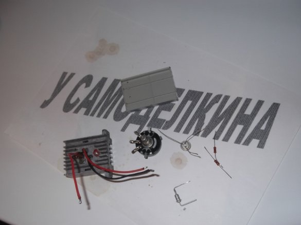
And so, let's go, we need:
• 1 resistor 560 ohms
• 2 resistors per 1 kOhm
• 1 trimming resistor per 10 Kom
• 1 transistor MP42, you can MP41 (I used one)
• 1 transistor P213
• 2 Zener diodes "D814B"
• Soldering accessories
• A piece of PCB (in my case a regular piece of plastic)
• Wires
• pliers
• Nippers
To begin with, we will change our scheme so that you can understand, and not to be confused
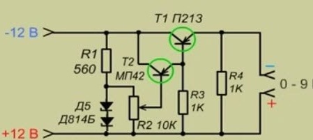
Now, now we have a circuit according to which we will assemble our device ..
When we have the circuit and all the details we need, we can safely proceed to the assembly
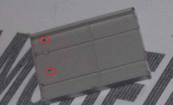
We take our plastic and make holes in it for installing parts
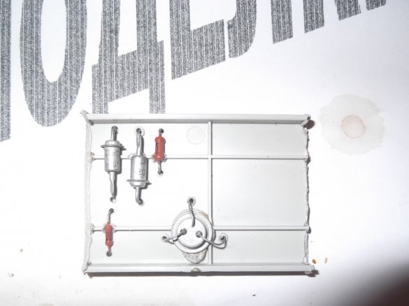
Next, install the parts on our piece of plastic (PCB)
Important!! The P213 transistor should be installed on the radiator and already in place with the radiator installed on our circuit. It is better to fix the wires with stasis with hot-melt adhesive or epoxy, because during the installation I managed to break off the output of the emitter
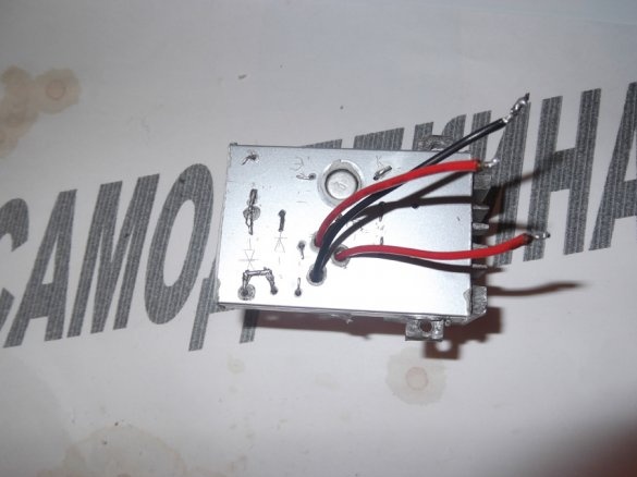
Next, we insert wires from P213 into holes on the other side of our design
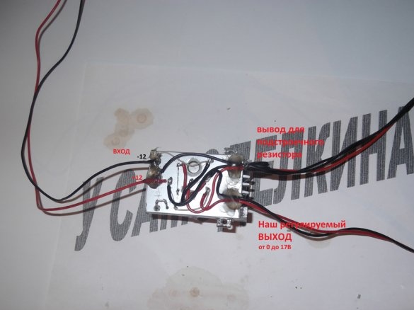
Then we collect everything according to the scheme, and here is what we get at the end
Thank you for your attention, good luck to everyone =)


