

The PWM controller is designed to control the speed of rotation of the polar motor, the brightness of the light bulb or the power of the heating element.
Benefits:
1 ease of manufacture
2 Availability of components (cost does not exceed $ 2)
3 Widespread use
4 For beginners, once again practice and please yourself =)
Once I needed a "device" to adjust the speed of rotation of the cooler. Why exactly I don’t remember. From the beginning I tried through a normal variable resistor, it was very hot and this was not acceptable for me. As a result, digging around on the Internet I found a circuit on the already familiar NE555 chip. This was a scheme of a conventional PWM controller with a duty cycle (duration) of pulses equal to or less than 50% (I will give graphs of how this works later). The circuit turned out to be very simple and did not require adjustment, the main thing was not to mess with the connection of diodes and a transistor. The first time he assembled it on a breadboard and tested it, it worked for half a turn. Later I already parted a small circuit board and everything looked neater =) Well now, let's take a look at the circuit itself!
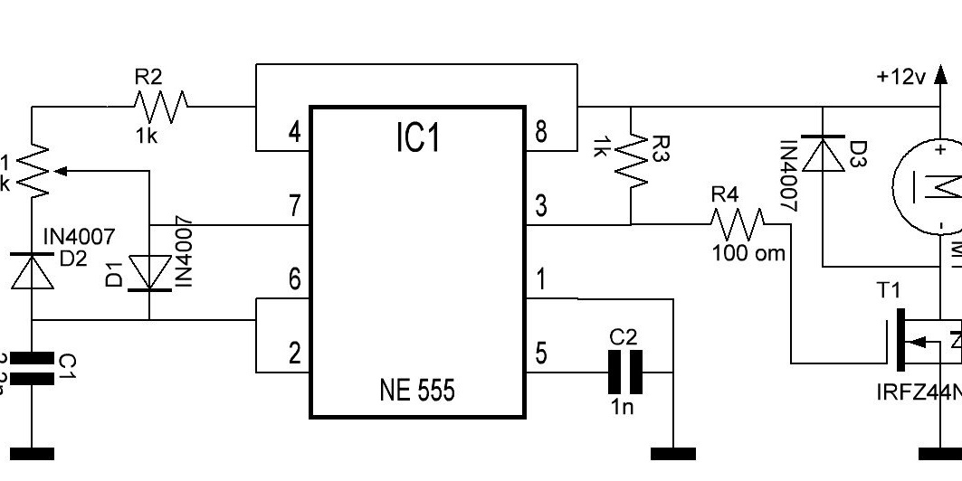
PWM controller circuit
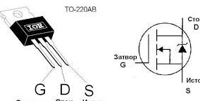
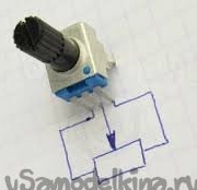
From it we see that this is a normal generator with a duty cycle controller assembled according to the scheme from a datasheet. And we change this duty cycle by the resistor R1, the resistor R2 serves as protection against short circuit, since the 4 pin of the microcircuit is connected to the ground through the internal key of the timer and when it is in the extreme position R1, it simply closes. R3 is a pull-up resistor. C2 is a frequency-setting capacitor. The IRFZ44N is a N channel mosfet. D3 is a protective diode that prevents the failure of the field during breakage of the load. Now a little about the duty cycle of pulses. The impulse rate is the ratio of its repetition period (repetition) to the duration of the impulse, that is, after a certain period of time, there will be a transition from (roughly speaking) plus to minus, or rather from a logical unit to logical zero. So this time interval between pulses is the same duty cycle.


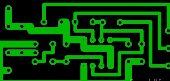
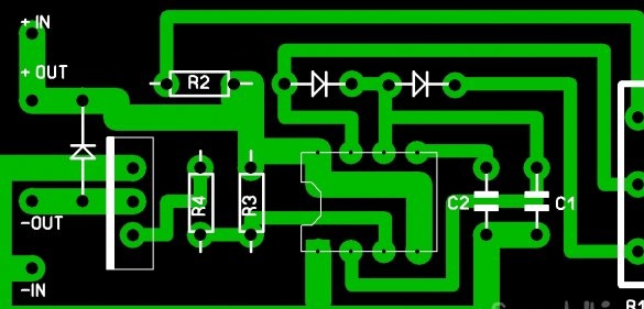
Below is a printed circuit board with the location of parts and without them
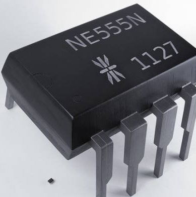
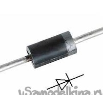
Now a little about the details and their appearance.The chip itself is made in a DIP-8 package, small-sized ceramic capacitors, resistors of 0.125-0.25 watts. Regular rectifying diodes at 1A (the most affordable is 1N4007 in bulk everywhere). Also, the chip can be installed on the socket if in the future you want to use it in other projects and do not solder it again. Below are the photos of the details.
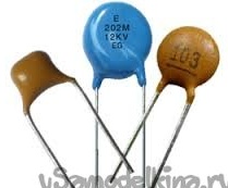
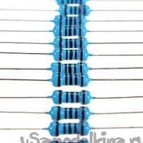
P.S: Capacitor rating can vary from 2.2 nanofarads to 4.7 nanofarads. The resistance of the resistor R4 is from 47-180 ohms.
P.P.S: I used this PWM controller to control: engine speed, bulb brightness and temperature of the heating element.
I wish you all creative success. Thank you for your attention!
From it we see that this is a normal generator with a duty cycle controller assembled according to the scheme from a datasheet. And we change this duty cycle by the resistor R1, the resistor R2 serves as protection against short circuit, since the 4 pin of the microcircuit is connected to the ground through the internal key of the timer and when it is in the extreme position R1, it simply closes. R3 is a pull-up resistor. C2 is a frequency-setting capacitor. The IRFZ44N is a N channel mosfet. D3 is a protective diode that prevents the failure of the field during breakage of the load. Now a little about the duty cycle of pulses. The impulse rate is the ratio of its repetition period (repetition) to the duration of the impulse, that is, after a certain period of time, there will be a transition from (roughly speaking) plus to minus, or rather from a logical unit to logical zero. So this time interval between pulses is the same duty cycle.

Duty ratio at middle position R1
Duty ratio at leftmost position R1

Duty ratio at extreme right position R
Below is a printed circuit board with the location of parts and without them


Now a little about the details and their appearance.The chip itself is made in a DIP-8 package, small-sized ceramic capacitors, resistors of 0.125-0.25 watts. Regular rectifying diodes at 1A (the most affordable is 1N4007 in bulk everywhere). Also, the chip can be installed on the socket if in the future you want to use it in other projects and do not solder it again. Below are the photos of the details.
P.S: Capacitor rating can vary from 2.2 nanofarads to 4.7 nanofarads. The resistance of the resistor R4 is from 47-180 ohms.
P.P.S: I used this PWM controller to control: engine speed, bulb brightness and temperature of the heating element.
I wish you all creative success. Thank you for your attention!