» Electronics »Simple and cheap do-it-yourself radio transmitter

Simple and cheap do-it-yourself radio transmitter


It will be about how to make the simplest and cheapest radio transmitter that anyone who does not even understand anything can assemble electronics.

The reception of such a radio transmitter takes place on a regular radio receiver (on a landline or in a mobile phone), at a frequency of 90-100 MHz. In our case, it will work as a radio extension for headphones from the TV. The radio transmitter through the audio plug connects to the TV through the headphone jack.

It can be used for various purposes, for example:
1) wireless headphone extension cord
2) Radio nanny
3) A bug for eavesdropping and so on.

To make it, we need:
1) Soldering iron
2) Wires
3) 3.5mm audio plug
4) Batteries
5) Copper lacquered wire
6) Glue (Moment or epoxy) but it may not be needed
7) Old boards from the radio or TV (if any)
8) A piece of plain textolite or thick cardboard


Here is his diagram, it is powered by 3-9 volts

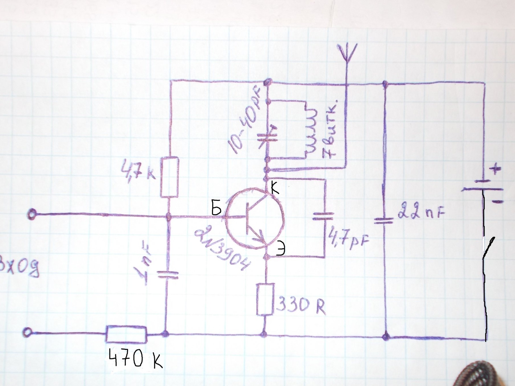
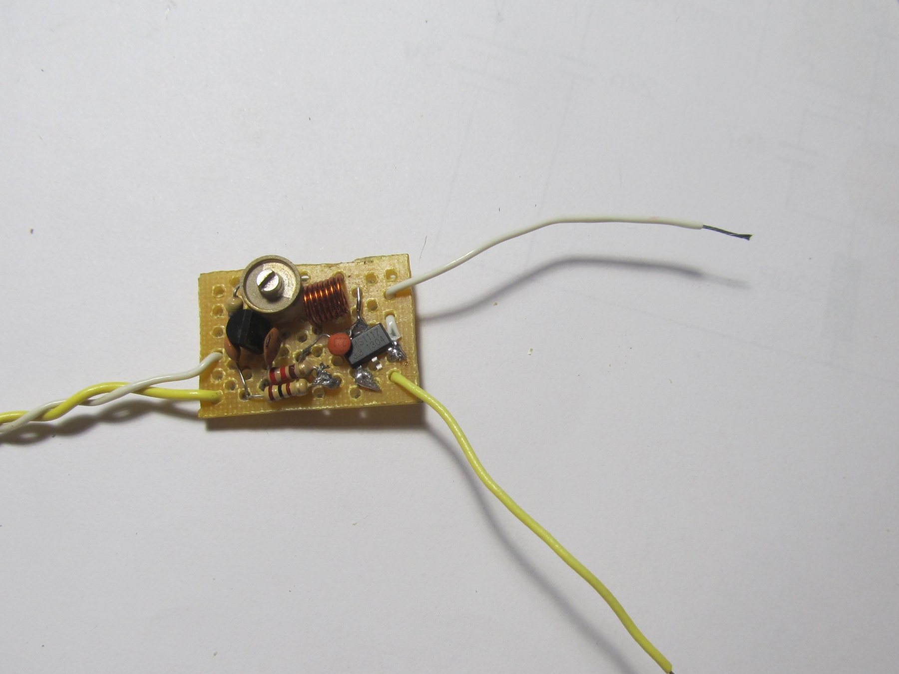
The list of radio parts for the circuit in the photo, they are very common and find them is not difficult. The AMS1117 part is not needed (just ignore it)

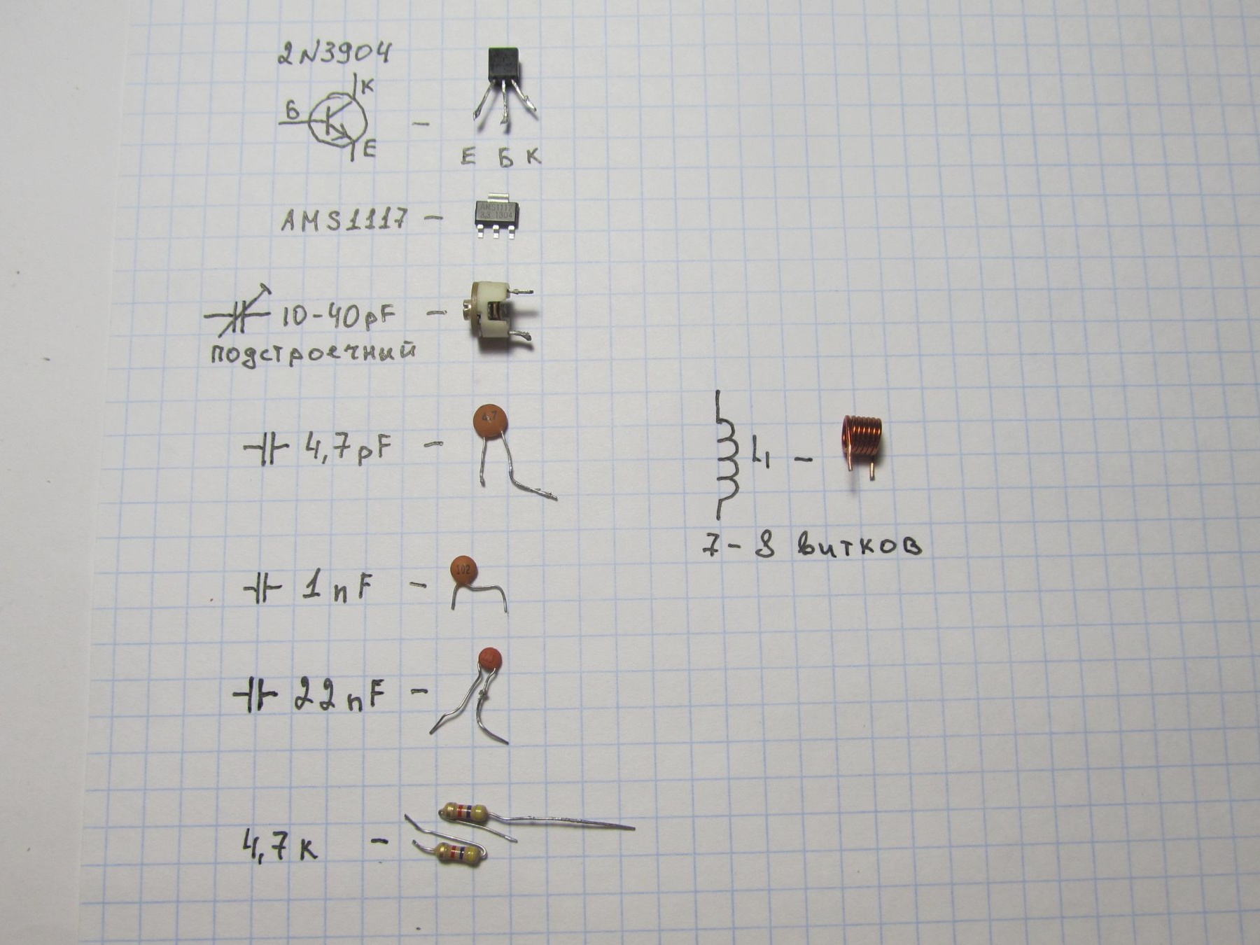
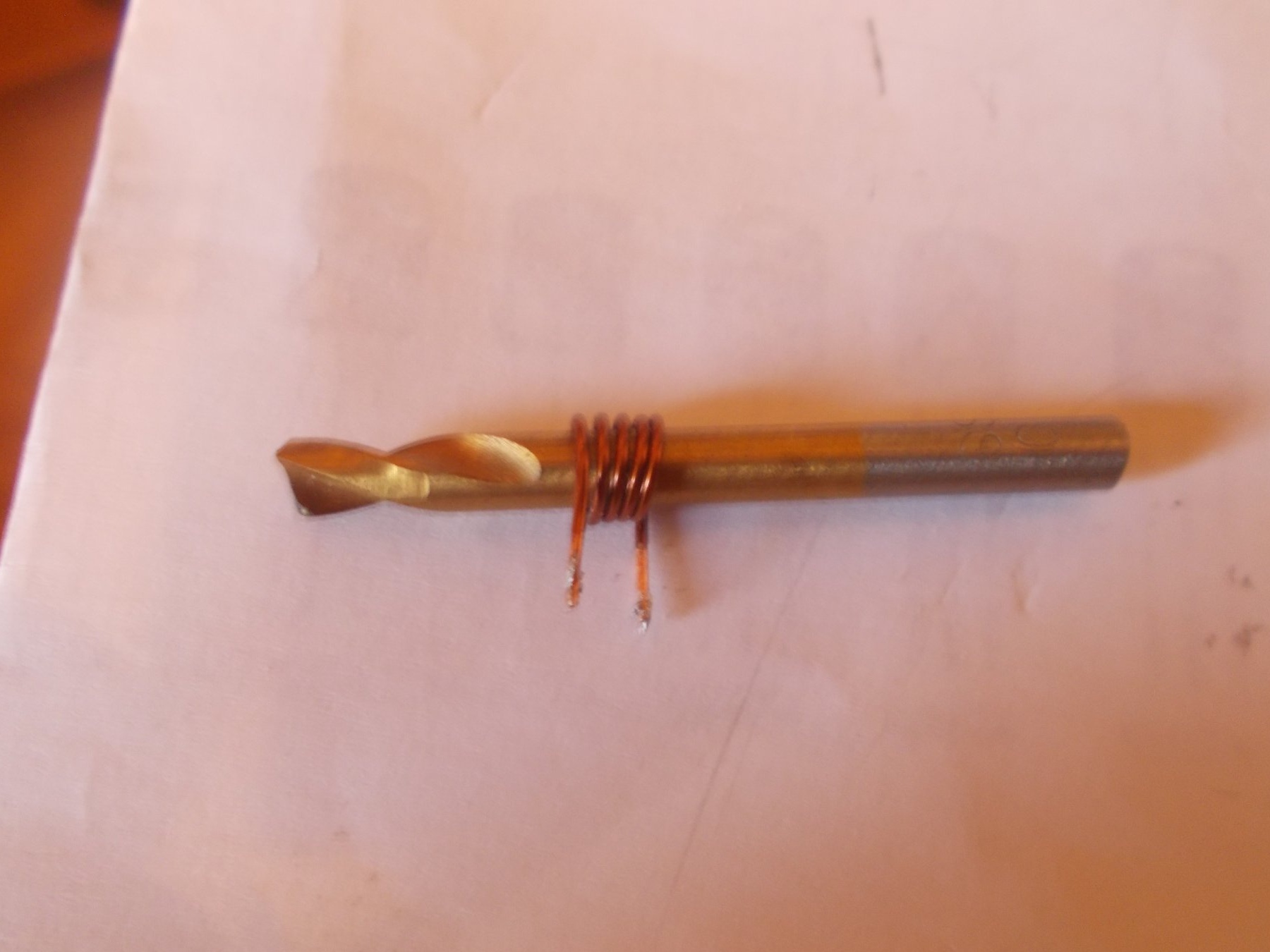
The coil should be wound in such parameters (7-8 turns with a wire with a diameter of 0.6-1 mm, on a mandrel of 5 mm, I wound on a drill of 5 mm)

The ends of the coil must be cleaned from varnish.

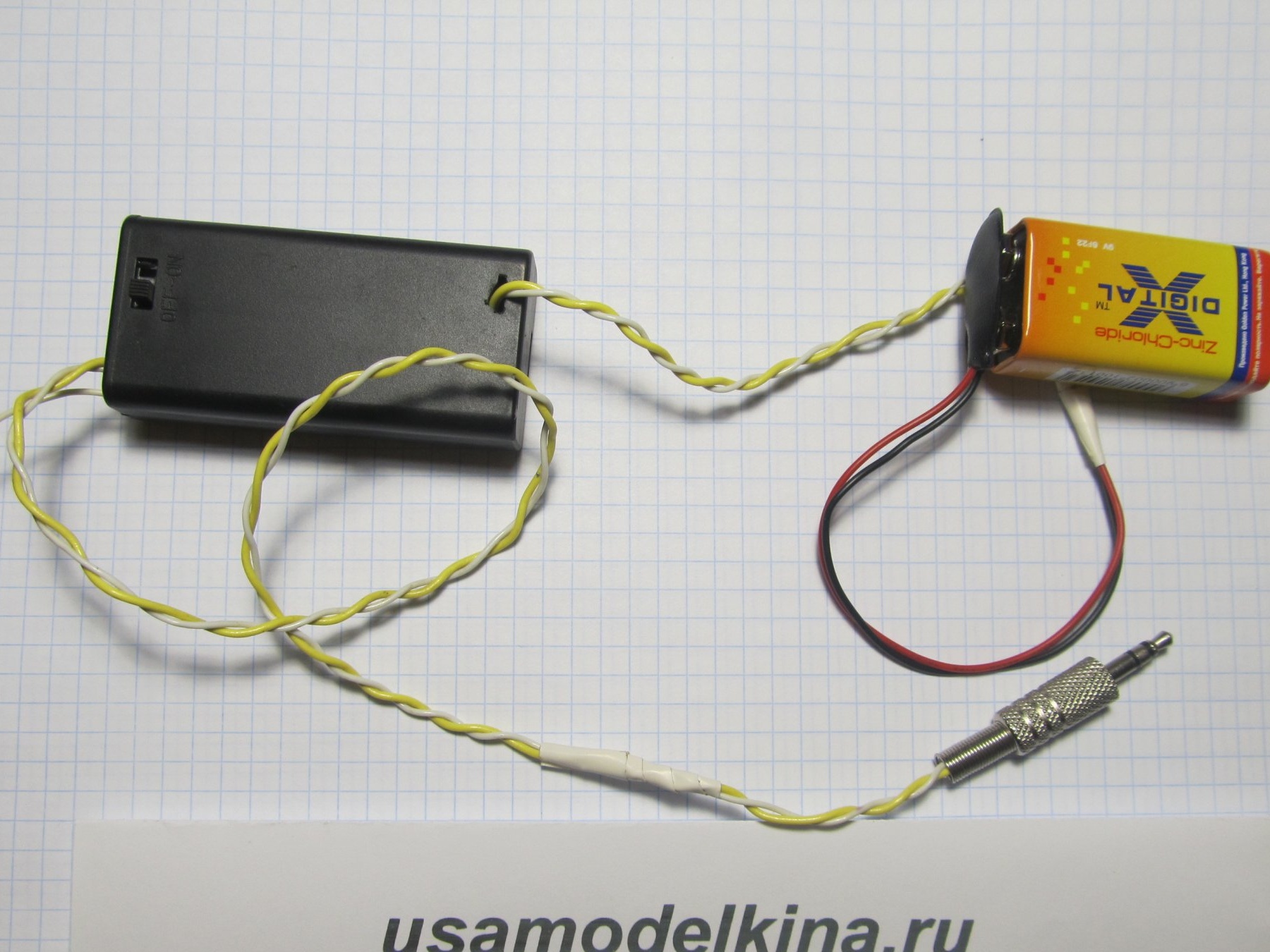
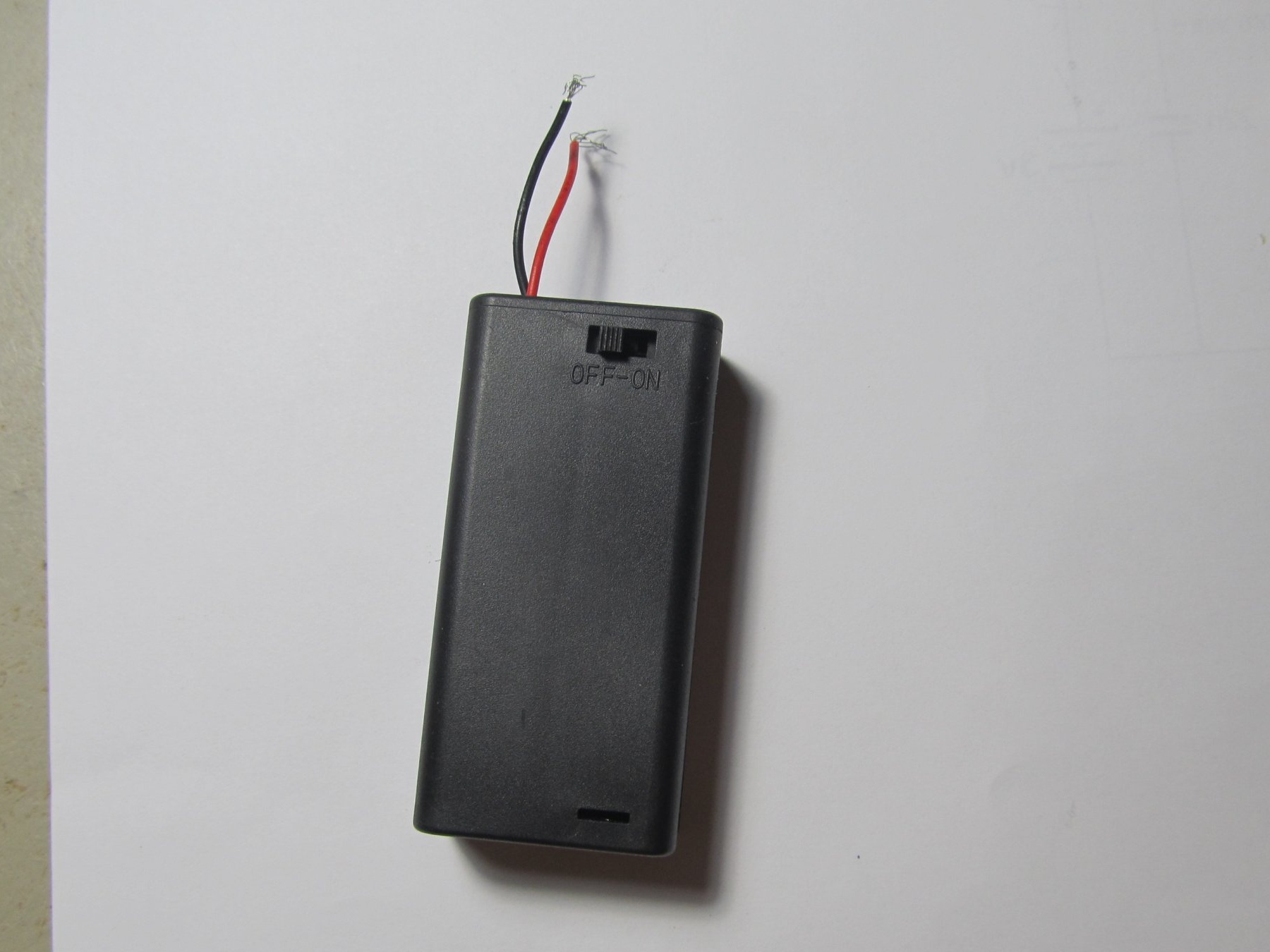
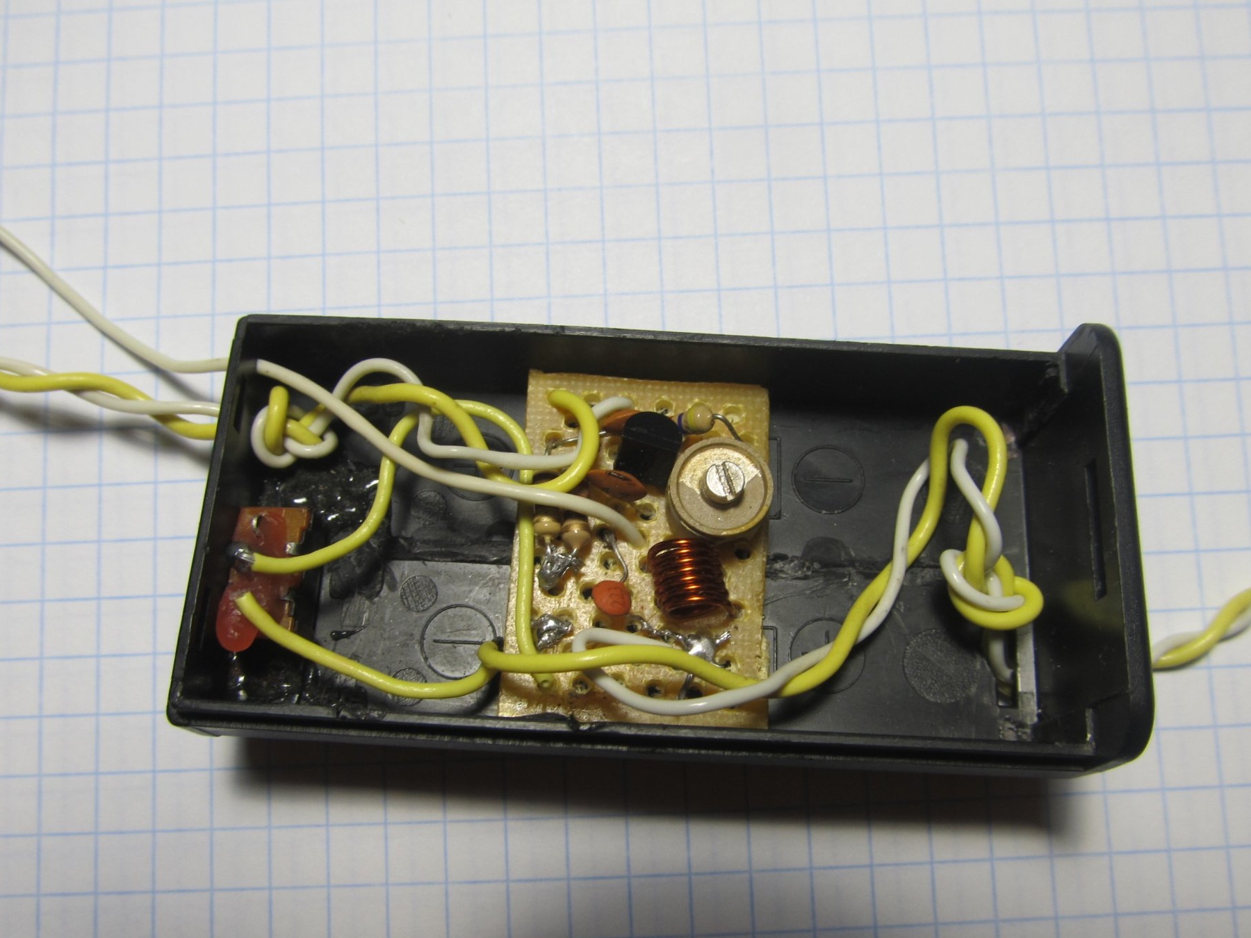
As a housing for the transmitter, a battery housing was taken


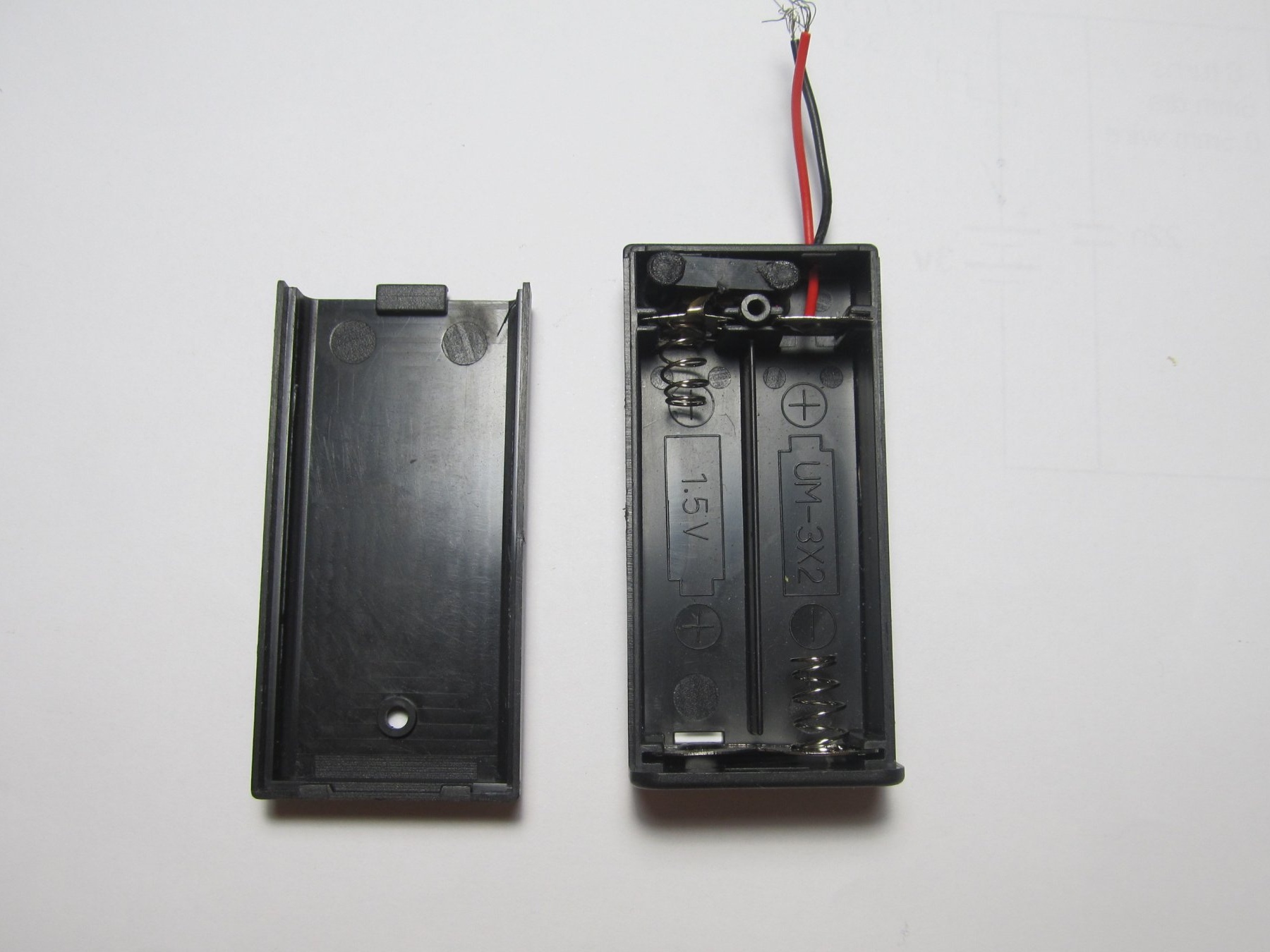
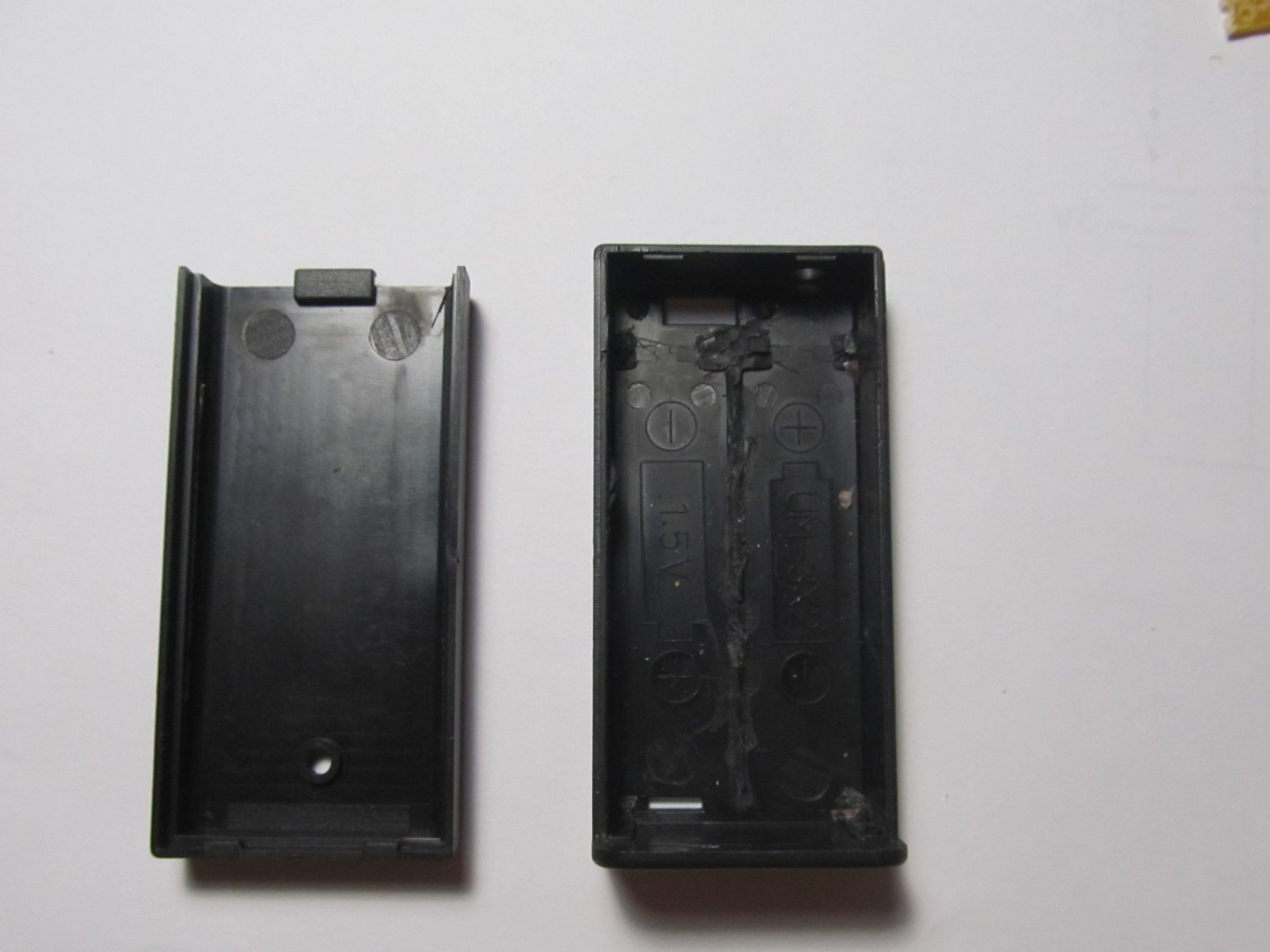
Everything was cleaned inside. For ease of installation

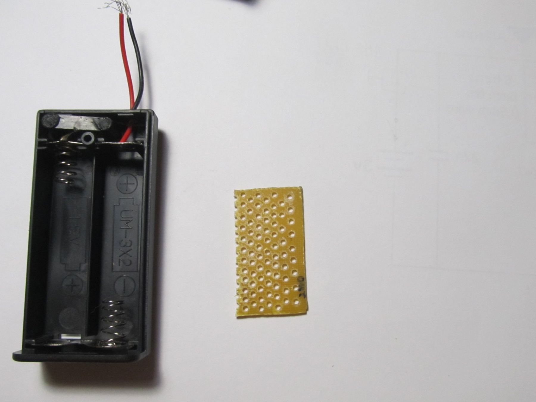
Next, we take textolite, cut it and drill many holes (it is better to drill more holes, it will be easier to assemble)

Now solder all the components according to the scheme
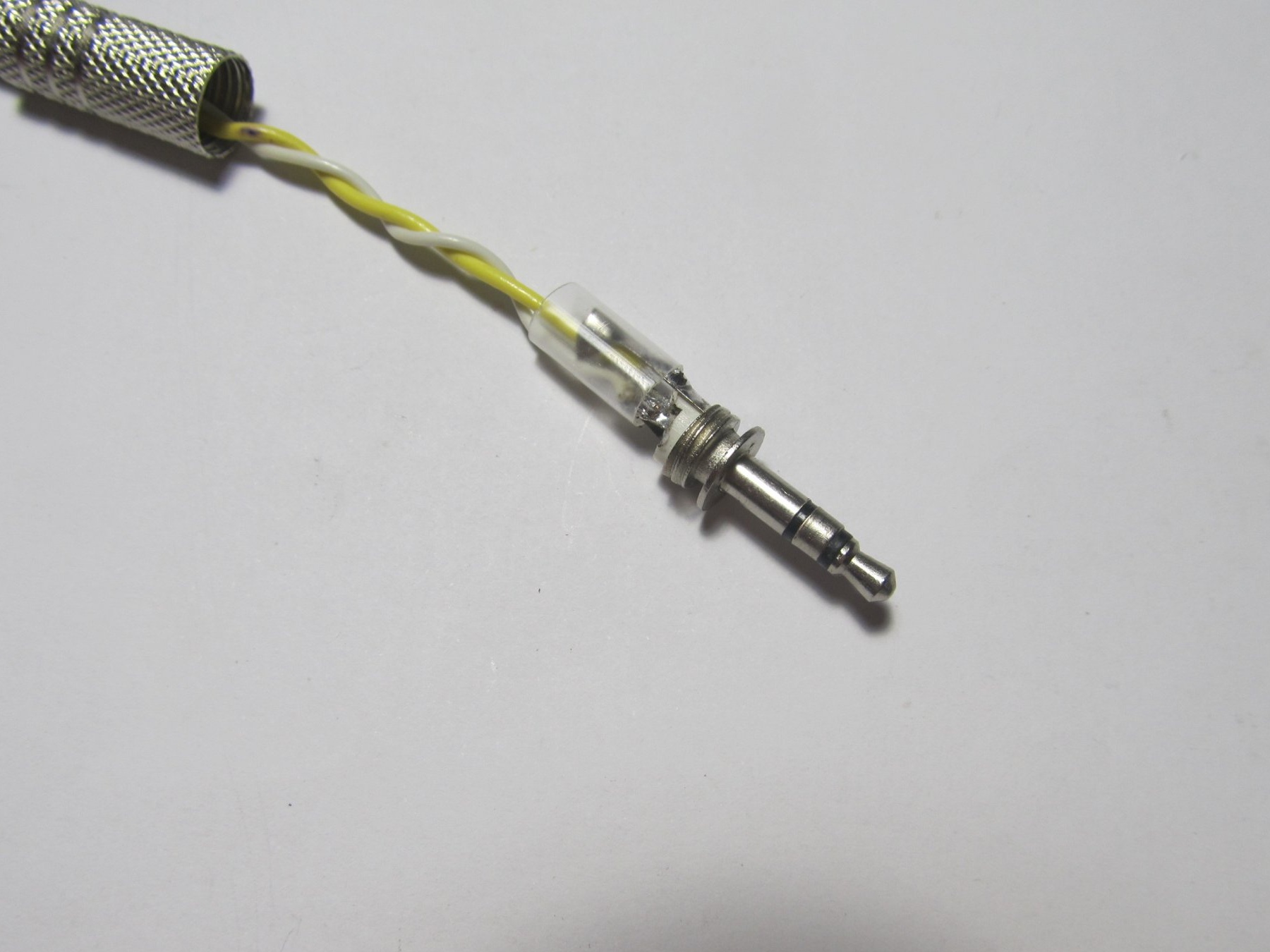
Take the audio plug

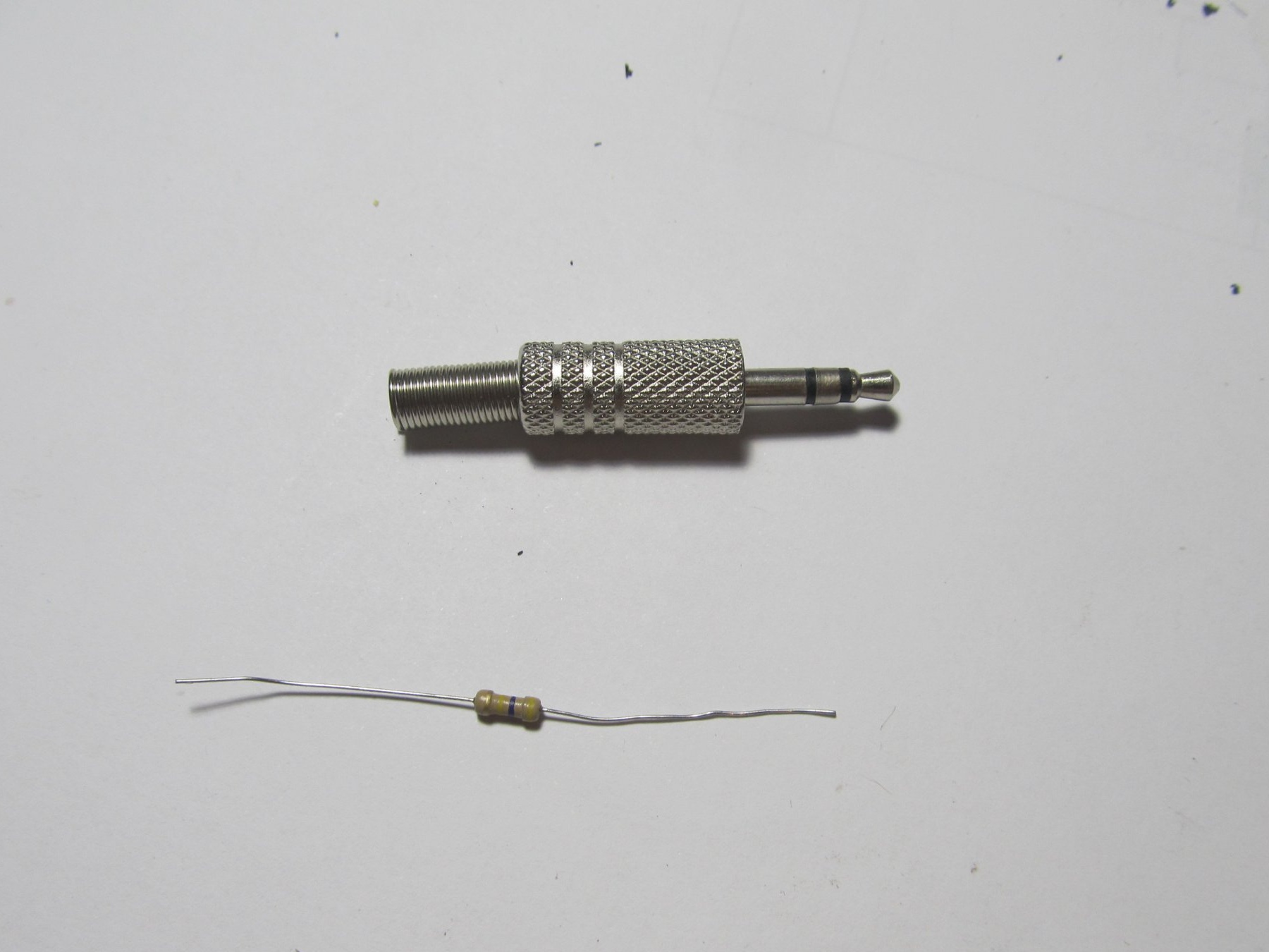
And solder wires to it, which are shown on the diagram as (input)

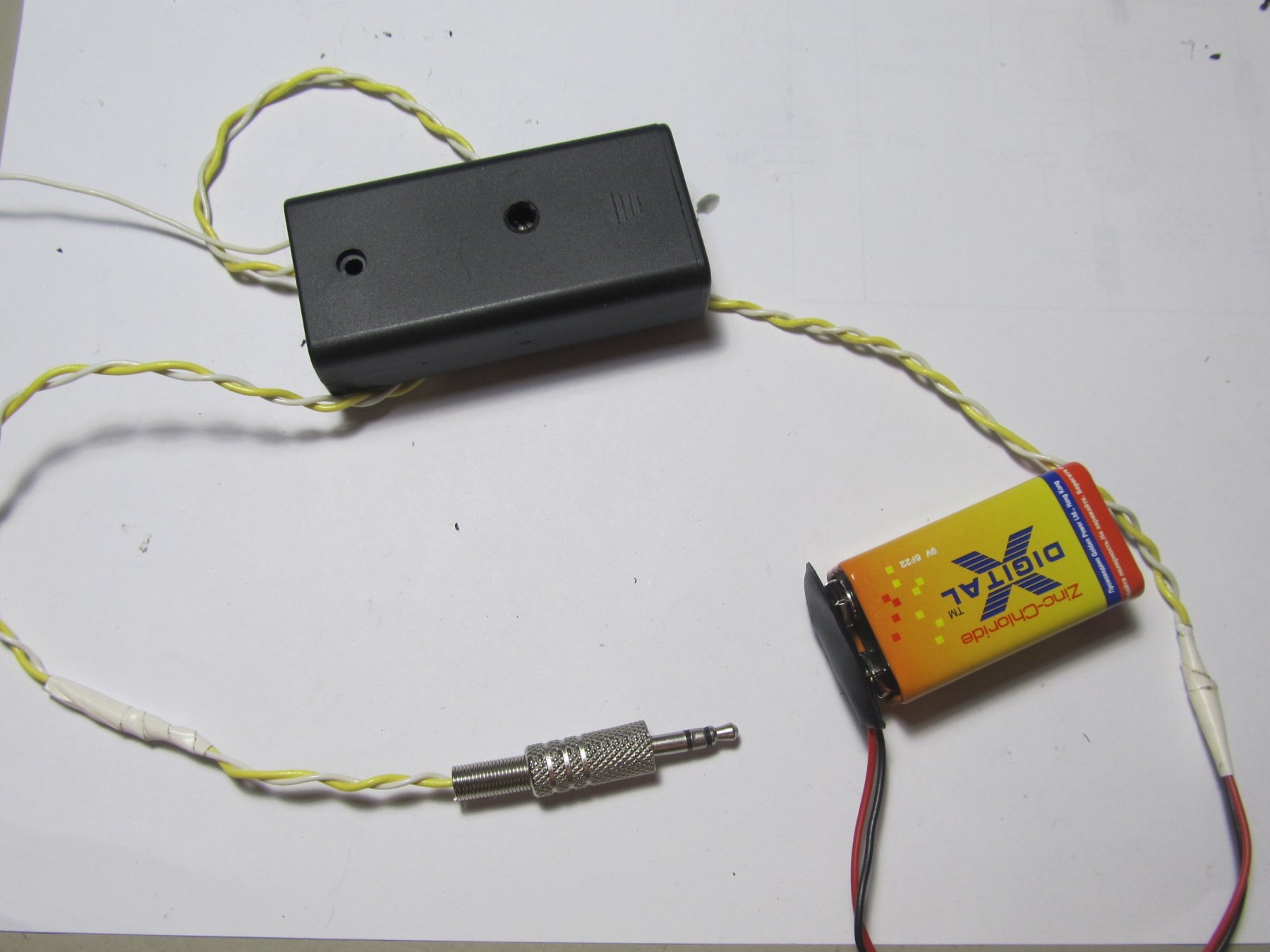
Next, we place the board in the case (it will be most reliable to glue it) and connect the battery


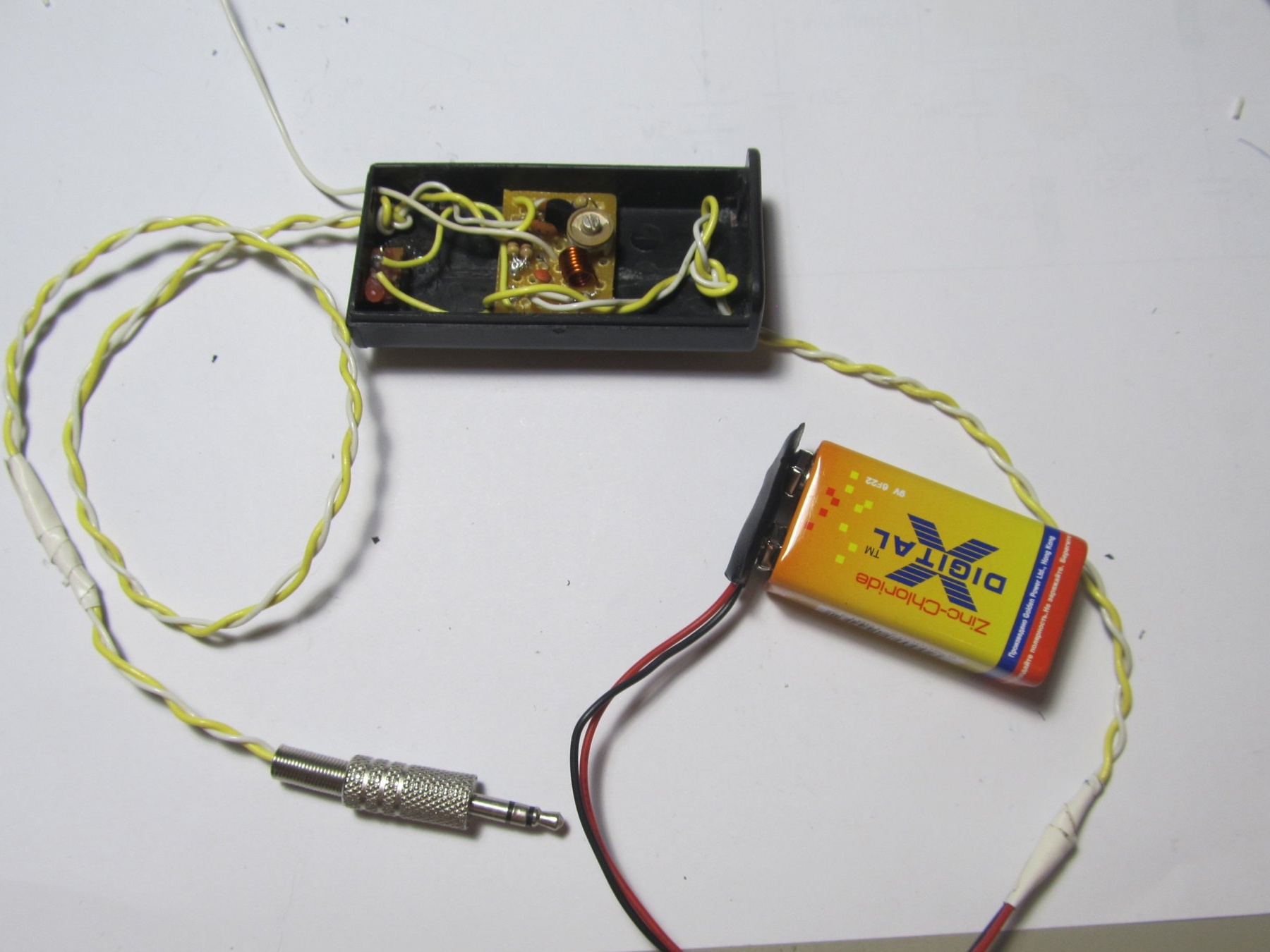
Now we connect our transmitter to the TV. On the FM receiver we find the free frequency (the one on which there is no radio station) and tune our transmitter to this wave. This is done by a tuned capacitor. Slowly twist it until we hear the sound from the TV on the FM receiver.

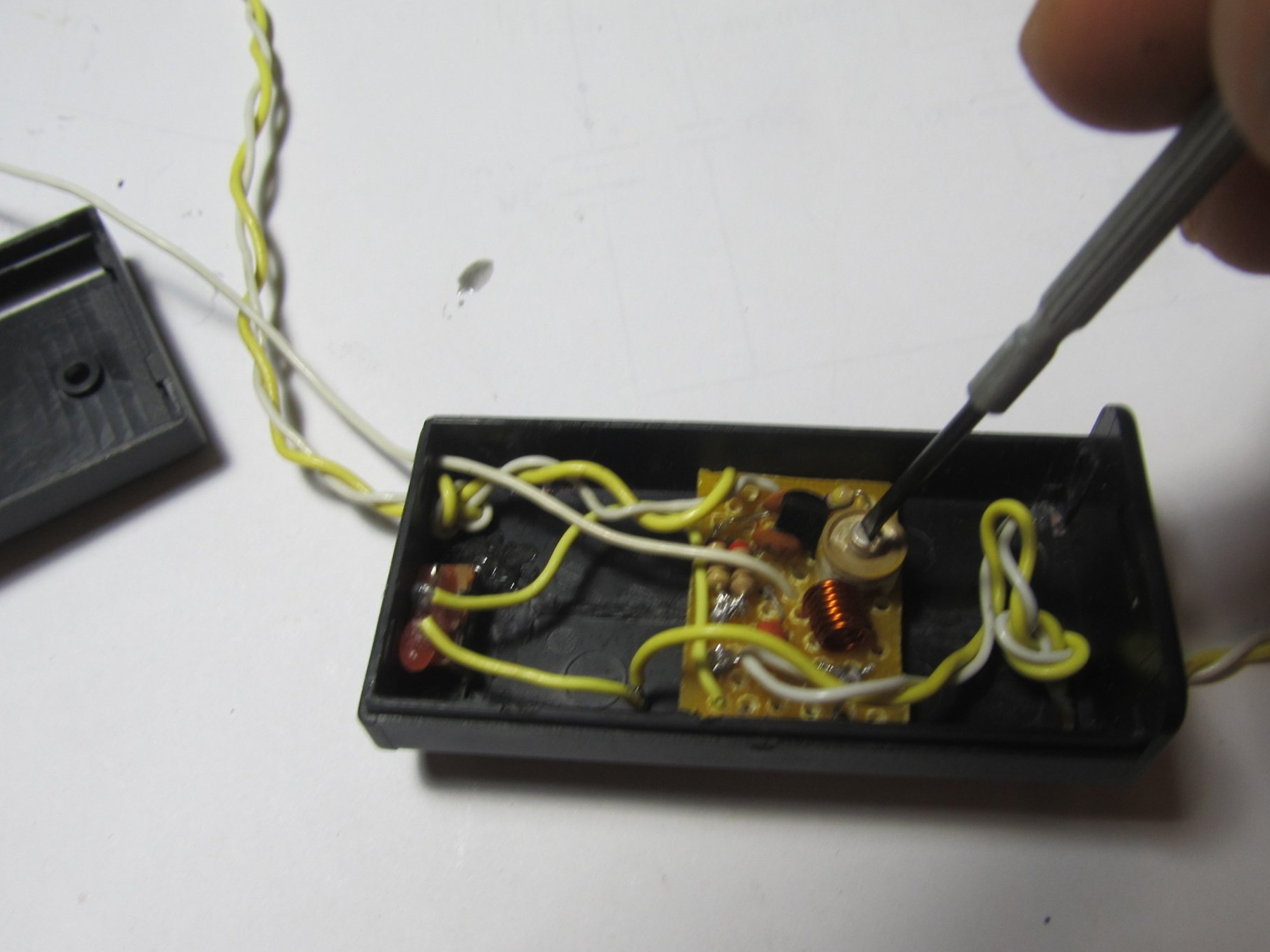
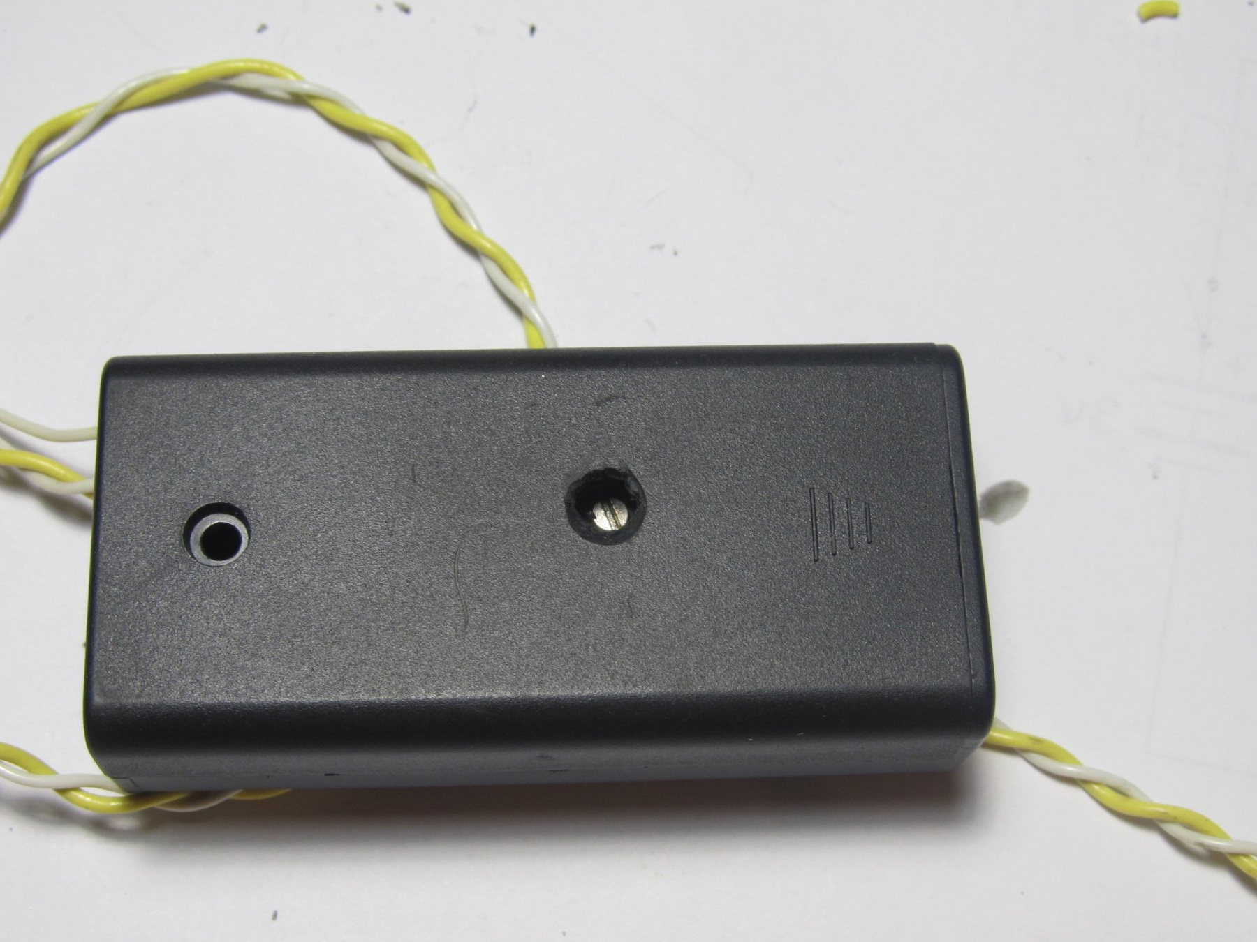
All our transmitter is ready to go.To make it convenient to tune the transmitter, I made a hole in the housing


Also, instead of an audio plug, you can put a microphone and then our transmitter will turn into a bug or a radio nanny. We place the transmitter in the room with the child, and in the kitchen we set up the radio and listen to what the child does there.
8.7
7.9
7.4

Add a comment

    • smilesmilesxaxaokdontknowyahoonea
      bossscratchfoolyesyes-yesaggressivesecret
      sorrydancedance2dance3pardonhelpdrinks
      stopfriendsgoodgoodgoodwhistleswoontongue
      smokeclappingcraydeclarederisivedon-t_mentiondownload
      heatirefullaugh1mdameetingmoskingnegative
      not_ipopcornpunishreadscarescaressearch
      tauntthank_youthisto_clueumnikacuteagree
      badbeeeblack_eyeblum3blushboastboredom
      censoredpleasantrysecret2threatenvictoryyusun_bespectacled
      shokrespektlolprevedwelcomekrutoyya_za
      ya_dobryihelperne_huliganne_othodifludbanclose
31 a comment
Guest Sergey
If my memory serves me, then this is a CT 315 transistor
Alexander Yurievich
It was described above that you can put P423, if you do this and change the polarity, then what kind of resistor to put instead of 330R and what voltage to turn on?
Sergey th
Is 470 kM resistor mandatory?
Guest Denis
Why in the circuit a 470 kΩ resistor at the input to the minus? Would he "kill" the entire input current signal?
Is it possible to replace 2n3904 with s9014 or h9014 (the datasheet is similar in my opinion)?
Can be assembled on a circuit board Traffic light. You will need 3 more LEDs (red, yellow and green) and 3 n-p-n transistors
I tried to assemble it but it didn’t work out. I wanted to ask if it is possible to use bredboard for a circuit or if it doesn’t work.

Rexant 11-9209 motion sensor
Breadboard
Neodymium magnets
Buttons
Connecting connectors
Mini rf rgb 24v controller
Battery compartment
Clamps
Clem
Diodes
I will be glad your suggestions thank you
Why not give it a try? It’s interesting. )))
And to read what I answered you is weakABOUT?
Cyril, you should not use them. And 1969 and 1982. This is germanium junk. They are either discarded or stored as a rarity.
Any (high frequency) Si is better. Sales soldered from a thread board ...
Thanks, only the polarity needs to be changed?
Any year is possible. If they are working, of course.))
It was just interesting how old your rarities are.;)
Sorry, it seemed to me that the old comment was being deleted
1969, are they possible?
1969 they
Or 1982
1969 P423 is it possible?
Read the message directly above yours and take it to the manual.
Change the polarity and select the base resistor. P423 should work, P422 - without warranty. And the supply voltage above 6 V is better not to do. What year are they?
Can I use P422 or P423 in it?
How to make it broadcast at 65.8-73 MHz?
I calculated a little according to well-known formulas: I got a frequency range from 57 to 122 MHz, so with 8 turns and a trimmer of 8.5-40 pF, this transmitter covers all frequencies of the FM range. We will soon check the operability of the circuit in practice. Who cares, leave the formula:
Inductance of the solenoid: L = NBS / I = mu0 * mu * N ^ 2 * S / L (where mu0 is the magnetic constant, mu for air is approximately = 1, N is the number of turns, L is the length of the solenoid (with 1 mm core wire - 8 mm), S = piR ^ 2 - the area penetrated by the lines of the magnetic field created in the circuit, if you wind on a 5 mm drill, then R = 2.5 mm.
Want to check - do not forget to transfer all values ​​to SI, so as not to be mistaken.
C is the capacitance of the capacitor (in my case, from 8.5 to 40 pF)
Next, substitute in the Thomson formula for the period, we find the frequency as 1 / T:
F = 1 / T = 1 / (2 * pi * root of (L * C))
Good afternoon! The question is, can you make 4 transmitters and one receiver for bite alarms with your own hands, so that when they squeak then the pager gives a signal?
1. Input wires should be twisted as in the photo. Their length should not be very large.
2. Try the following:
a) swap input wires,
b) rearrange the 470 kOhm resistor to its usual place - in the base circuit,
c) reduce its value every 5 times,
d) increase the capacity for nutrition,
e) to supply an electrolyte of any capacity with a capacity of 16 V and higher in parallel with the existing capacitor.
Hey. There is a question. So far, I am just beginning steps in radio electronics. So here.
In local stores I did not find a variable at 10-40, only at 5-25. Soldered. the truth is not on the board, but mounted. Earned. Only at the receiver, even though the voice is clear, is there a monotonous hum. What could it be?
I want to use your "homemade" in the organization of school radio. Is it possible? then will it be possible to buy from you?
Good day!
I have a question for you: what is the AMS1117 chip for? What function does it perform? It is not indicated on the diagram. I understand that you can without it. But still I'm interested. And what kind of domestic transistor can be replaced. Here you go. I want to repeat your scheme.
Tell me, I assembled everything as in the diagram, but when I turn it on, there is a circuit, why is this?
Perhaps the transistor could not withstand the current you created by substituting a resistor of a different nominal value! Check the transistor!
Please tell me what to do. I assembled this circuit, but there was no such variable capacitor, and I took from 3 to 35 PF, and also put 120 on the emitter instead of 330 Ohm (if I change it). Why might not work? Everything is connected in the same way as in the diagram, but the wave is not caught (
What to do? What wave can it be? And which antenna is better to put?
Vladislav
Please tell me what to do. I assembled this circuit, but there was no such variable capacitor, and I took from 3 to 35 PF, and also put 120 on the emitter instead of 330 Ohm (if I change it). Why might not work? Everything is connected in the same way as in the diagram, but the wave is not caught (
What to do? What wave can it be? And which antenna is better to put?

We advise you to read:

Hand it for the smartphone ...