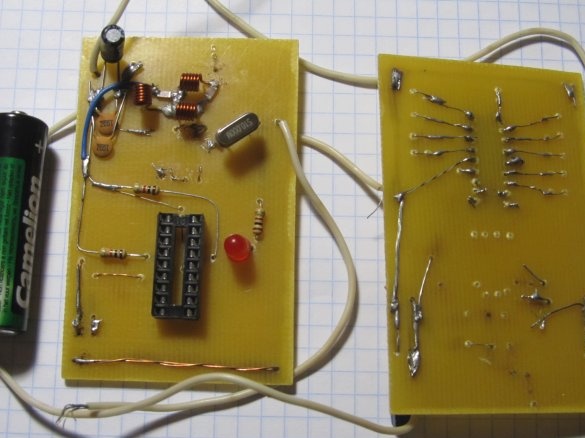
In this article, you will see how to do radio control for 10 teams do it yourself. The range of this device is 200 meters on the ground and more than 400m in the air. Pressing the buttons can be done in any order, although all at once everything works stably. With it, you can control different loads: the gate the garageby the light models planes, cars, and so on ... In general, anything, it all depends on your imagination.
For work, we need a list of parts:
1) PIC16F628A-2 pcs (microcontroller)
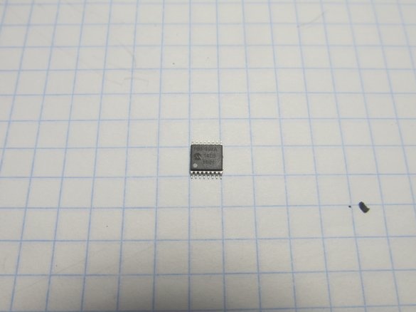
2) MRF49XA-2 pcs (radio transmitter)
3) Inductor 47nH (or reel yourself) -6pcs
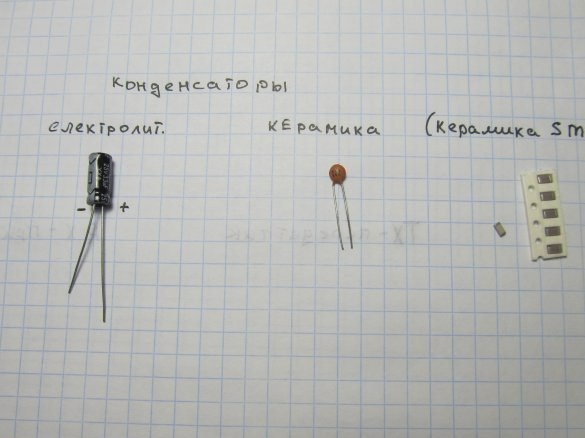
Capacitors:
4) 33 microfarads (electrolytic) -2 pcs
5) 0.1 uF-6 pcs
6) 4.7 pF-4 pcs
7) 18 pF-2 pcs
Resistors
8) 100 ohm-1 pc
9) 560 ohm-10 pcs
10) 1 Kom-3 pcs
11) 1 pc LED
12) buttons - 10 pcs
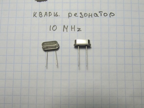
13) Quartz 10MHz-2 pcs
14) Textolite
15) Soldering iron
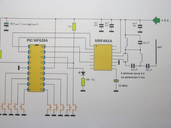
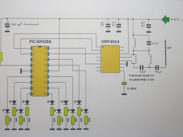
Here is a diagram of this device
Transmitter
And the receiver
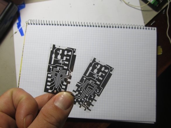
As you can see, the device consists of a minimum of details and is within the power of everyone. You just have to want it. The device is very stable, it works immediately after assembly. The circuit can be done as on a printed circuit board. And a hinged installation (especially for the first time, it will be easier to program). To start, we make a fee. Print out
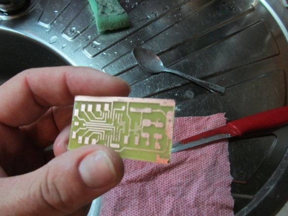
AND poison board
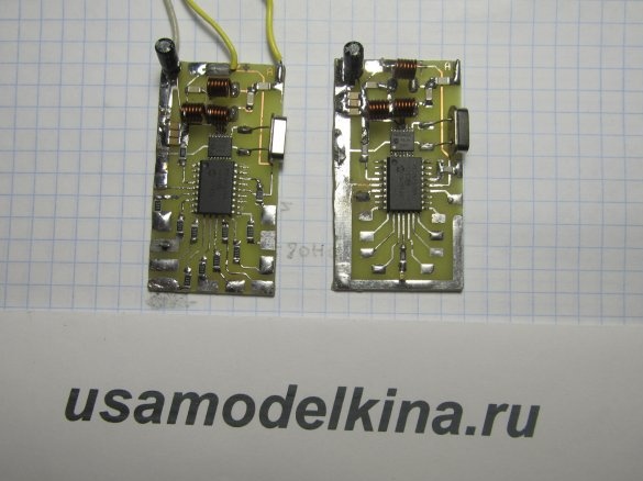
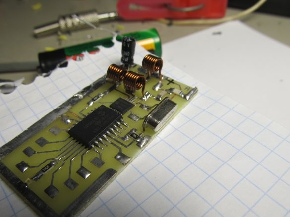
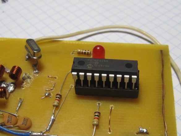
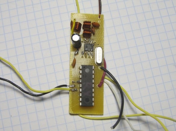
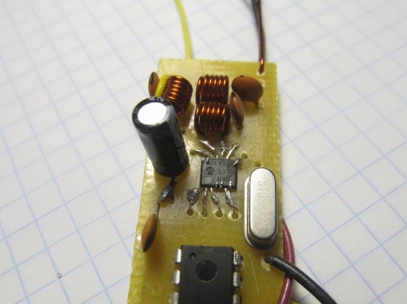
We solder all the components, it is better to solder the PIC16F628A with the latest one, since it will still need to be programmed. First, solder MRF49XA
The main thing is very neat, she has very subtle conclusions. Capacitors for clarity. The most important thing is not to confuse the poles on the 33 μF capacitor since it has different conclusions, one +, the other -. Solder all other capacitors as you like, they have no polarity on the terminals
Coils can be used purchased 47nH but it is better to reel yourself, they are all the same (6 turns of 0.4 wire on a 2 mm mandrel)
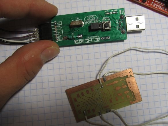
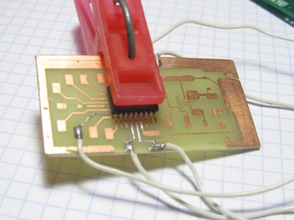
When everything is soldered, everything is well checked. Next, take the PIC16F628A, it needs to be programmed. I used PIC KIT 2 lite and a homemade socket
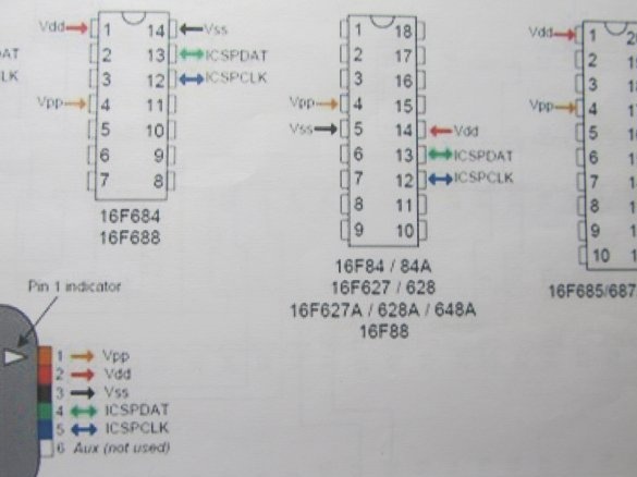
Here is the connection diagram
It's all simple, so don't be alarmed. For those who are far from electronics, I advise you not to start with SMD components, but to buy everything in DIP size. I did it myself for the first time
And it all really worked the first time
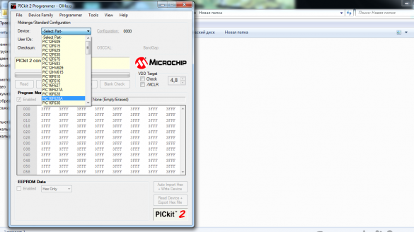
Open the program, select our microcontroller
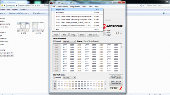
Click insert firmware file and click WRITE
Similarly, with another microcontroller.
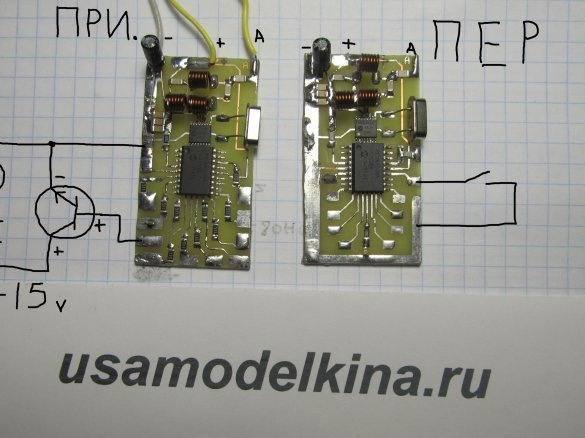
The TX file is for the transmitter, and RX is for the receiver. The main thing then is not to confuse the microcontrollers. And solder the microcontrollers to the board. After you collect, in no case do not connect the load immediately to the board, otherwise burn everything.The load on the board should be connected through a powerful transistor as in the photo
On the diagram, the LEDs are purely for checking the performance.
Here are the firmware files


