We will need:
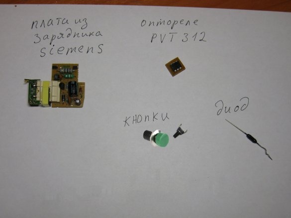
- unnecessary mobile phone charger
- optical relay or triac optocoupler for 300 - 400 volts
- rectifier diode (which is) - 2pcs
- AA or AAA battery
- button with normally closed contact
- button with normally open contact
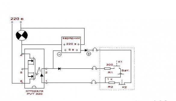
Here is a diagram on an opto-switch to illuminate a bathroom mirror. For other purposes, the circuit is the same, just another optical switch or triac optocoupler is possible, for example: PVX6012, MOC3052M, MOC3063M, MOC3083M.
How does it work:
1. The LED in the opto-relay is off. Field effect transistors are closed. The current does not go.
2. They pressed the normally open button K1, the light-emitting diode in the opto-relay was lit from the battery, the field-effect transistors opened, the current went through the load and, connected in parallel, the charger. Now, if you release the K1 button, the LED in the opto-relay will continue to light from the charger.
3. They pressed the normally closed button K2, they disconnected the power supply circuit of the LED - there is no current until K1 is pressed again.
Before assembly, be sure to check the resistance between the mains plug and the outlet of the charger used - it should be infinite or at least tens of Mohms.
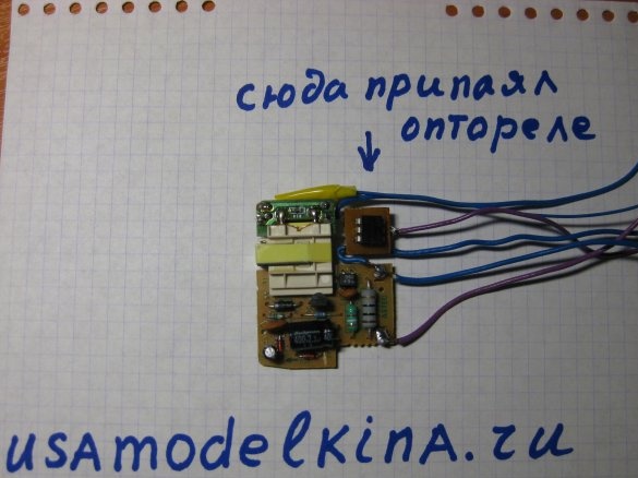
We make a neat socket for the opto-relay, solder its contacts according to the diagram to the board from the charger, fill everything with a glue gun. Naturally do not forget about the bends.
Resistors R1 and R2 300 - 1000 OM must be selected based on the passport control current of the optical relay or triac optocoupler.
I think it is not advisable to replace the batteries with a battery - the discharge is very small.
It works clearly, nothing gets warm.
If instead of buttons you install transistor switches with different sensors, you can easily and safely control any electrical equipment in the house and in the country.


