
Many are interested in how to make portable speakers or speakers for smartphones and tablets. However, before proceeding with the manufacture of the speakers themselves, you need to take care of the amplifier. In this article we will review the video, which is devoted to the assembly of a simple amplifier.
Let's start by watching the author’s footage.
[media = https: //www.youtube.com/watch? v = FRXbFRzczF8]
So, what do we need to assemble an amplifier:
- connector for crown;
- crown at 9 volts;
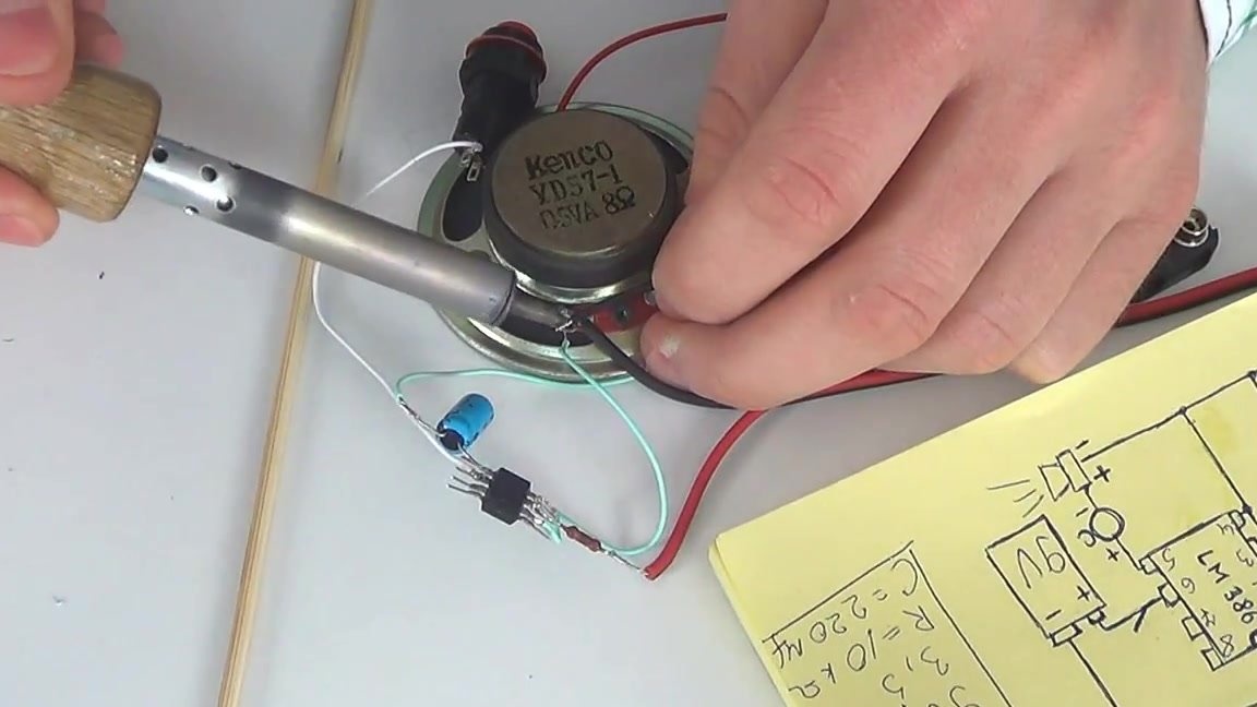
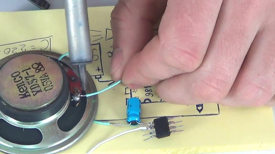
- speaker 0.5-1 W and a resistance of 8 ohms;
- 3.5 mm mini jack;
- 10 ohm resistor;
- switch;
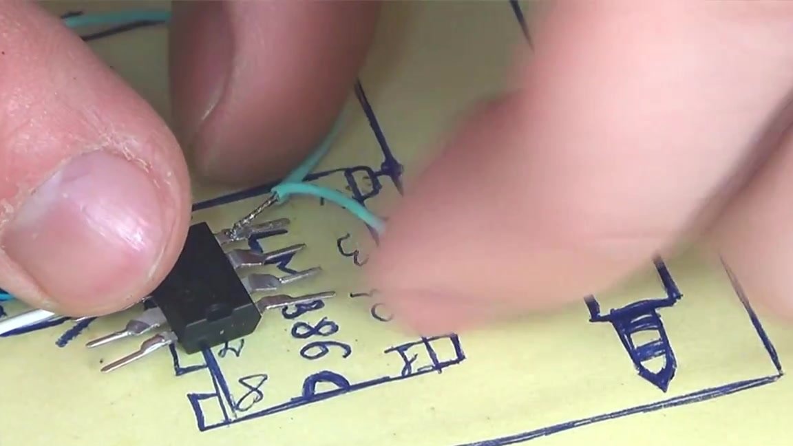
- chip LM386;
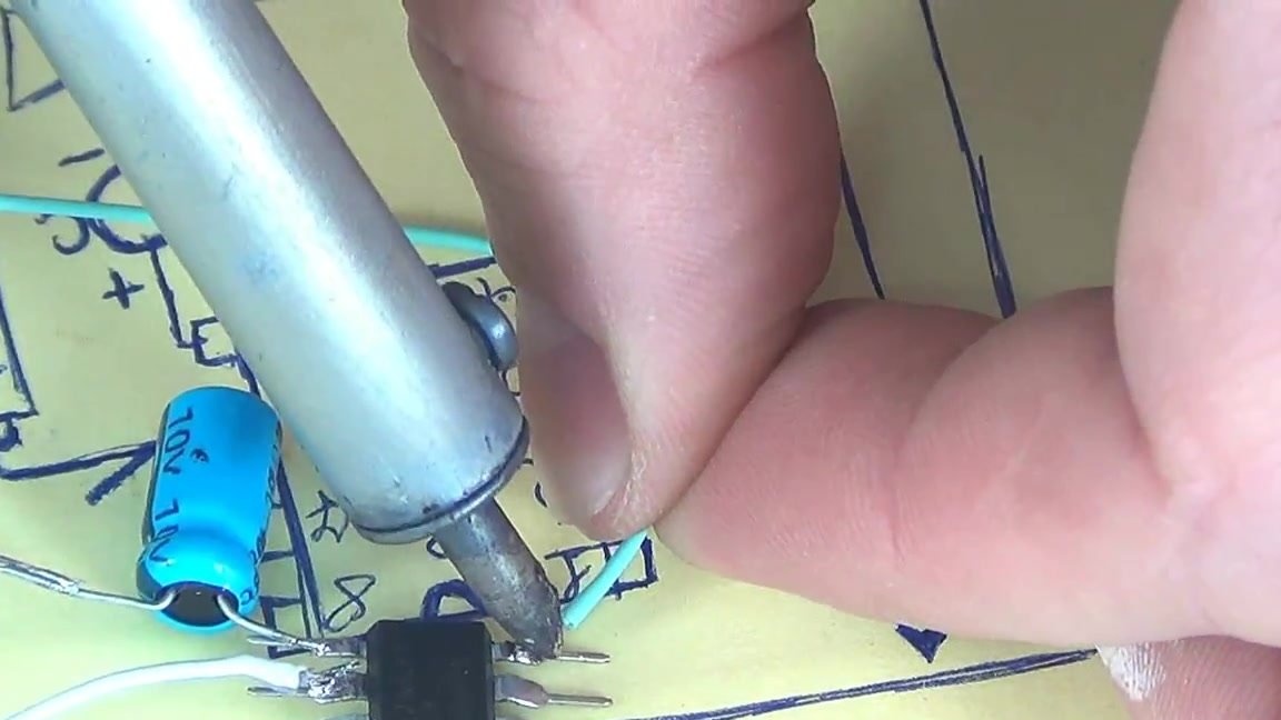
- 10 volt capacitor.
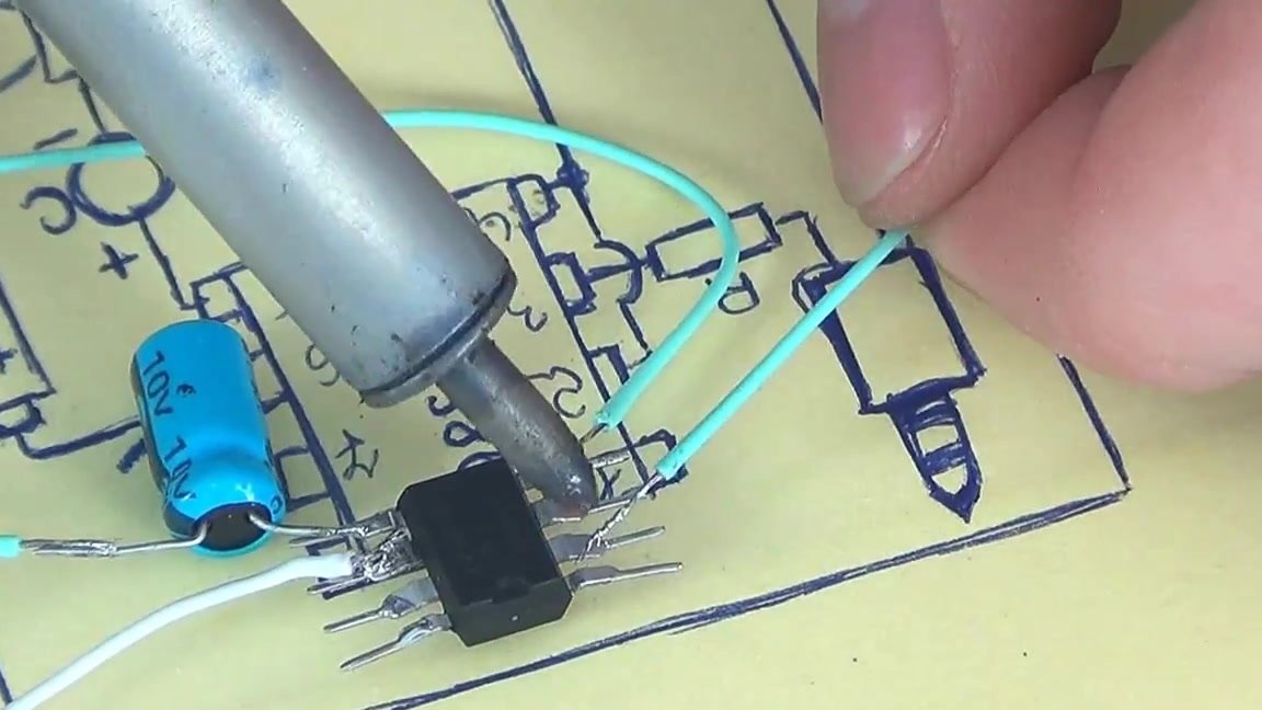
So that the assembly process does not seem very complicated, we present to your attention a diagram of the future amplifier.
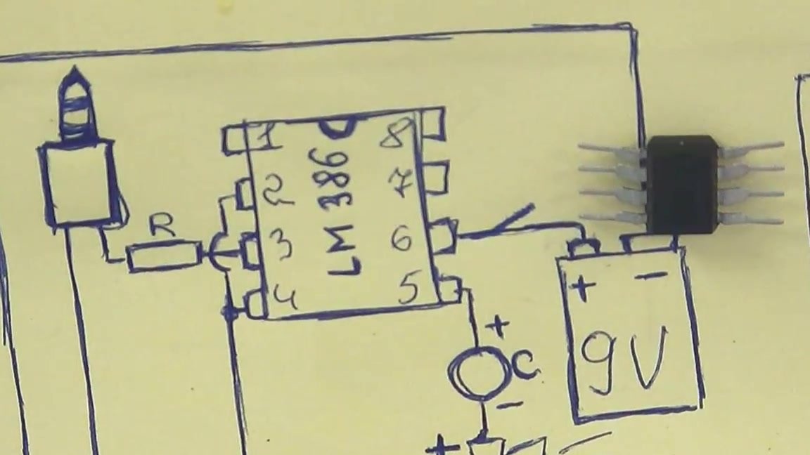
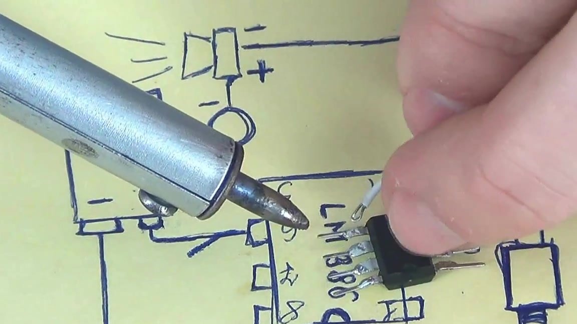
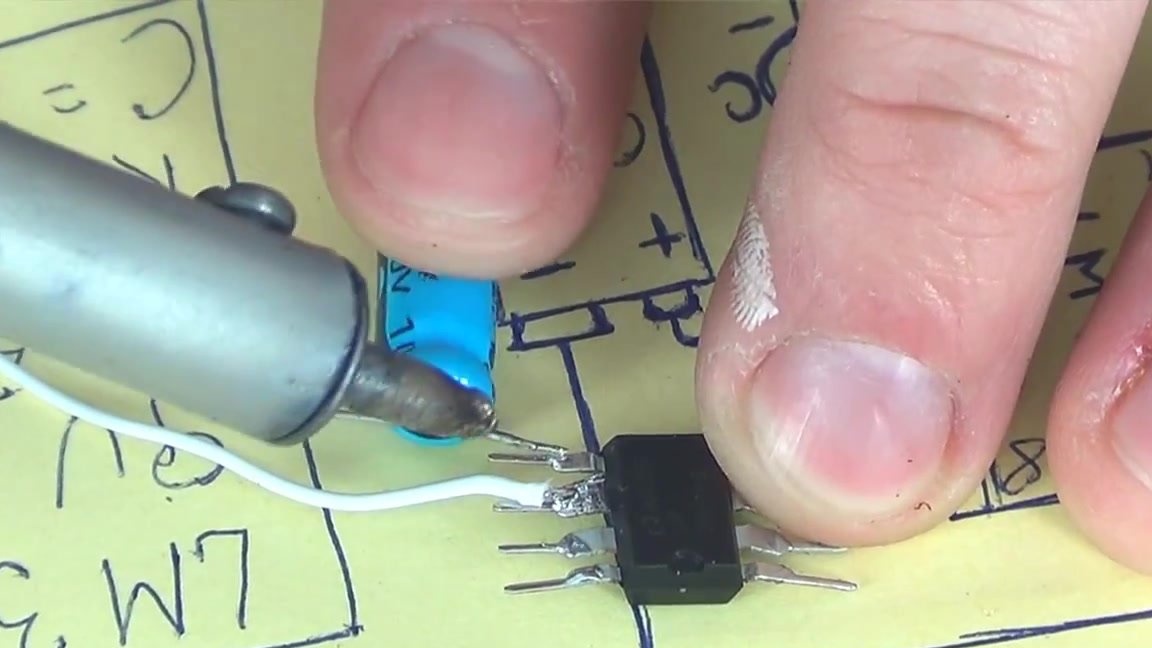
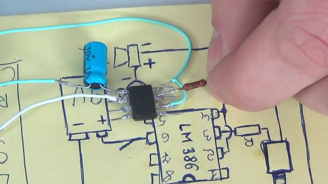
Looking at the microcircuit from a closer distance, you can see that it has four legs on both sides. In total, 8 paws are obtained. In order not to confuse or flip the chip upside down and thereby make a mistake with soldering, a small mark similar to a semicircle is provided on the microcircuit. This label should be on top.
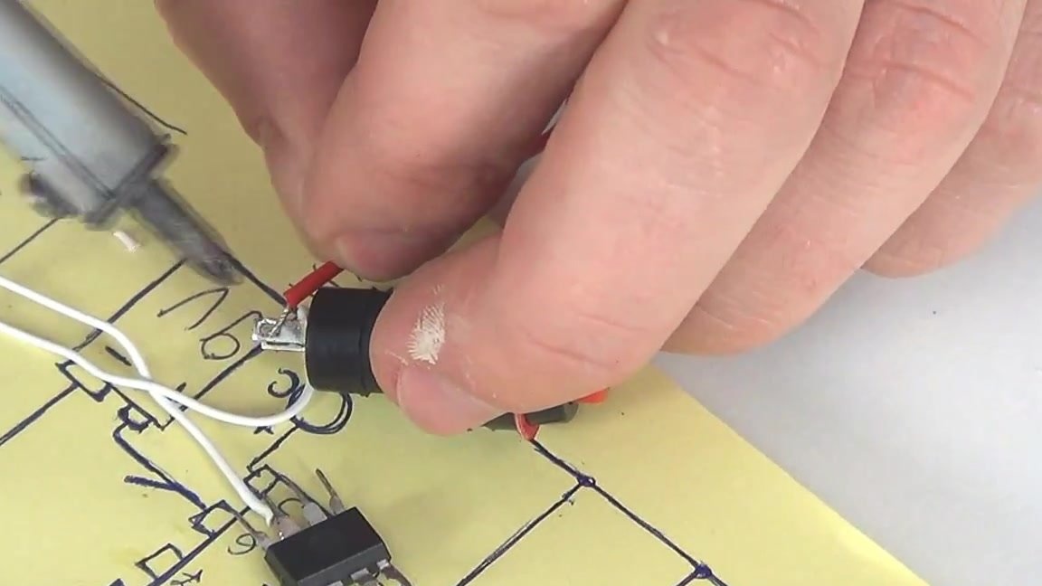
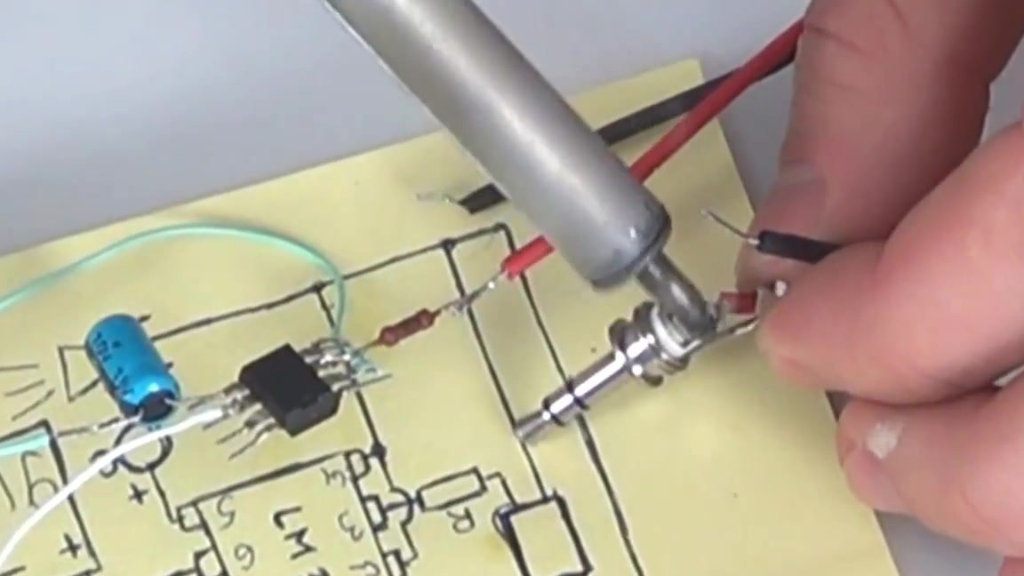
Let's start by soldering the first wire, which will go to the switch and the positive contact of the crown. This wiring must be soldered to the sixth foot of the microcircuit, that is, the second from the bottom on the right side.
The next end of the wiring must be soldered to the switch. It is worth noting that according to the author of the idea, the circuit itself does not present any difficulties and even someone who does not have special skills can cope with the assembly electronics.
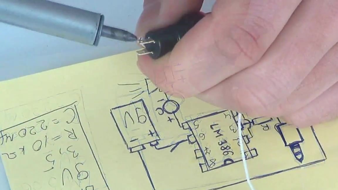
After successfully soldering the first wire, you need to go to the second contact of the switch, which is currently free. Here you need to solder the positive wire coming from the crown connector. After such a simple soldering, we can say that the first stage of manufacturing the amplifier was successfully completed.
Let's move on to the next foot, which is marked with the number 5 on the diagram and located directly under the sixth foot, that is, the one to which we soldered the wire at the previous stage of work.Solder the positive contact of the capacitor to this foot.
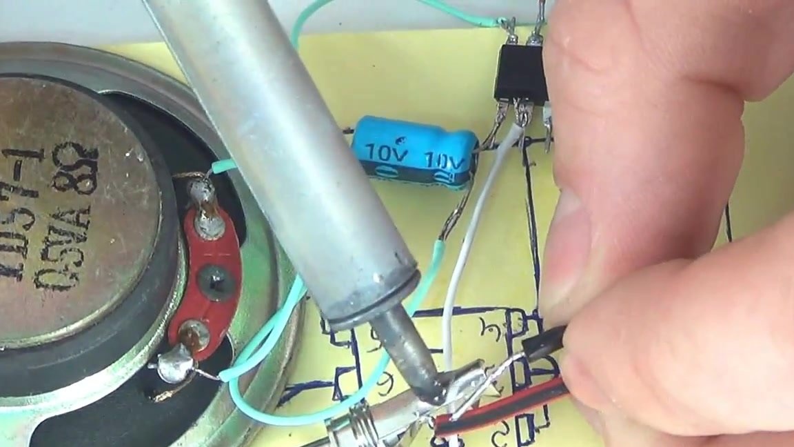
From the capacitor we still have a negative contact, which must be soldered to the positive contact of the speaker. If you wish, you can refuse direct soldering of the capacitor to the speaker in order to protect it from possible damage, as the author does. In this case, you need to shorten the contact of the capacitor and lengthen it with wiring.
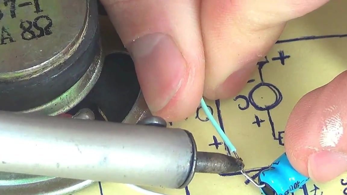
After that, you can solder the wires from the minus of the capacitor to the plus of the speaker.
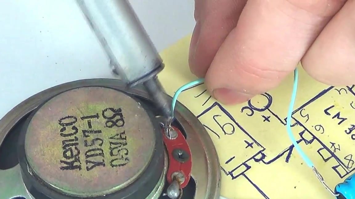
The minus contact of the speaker must be soldered to the fourth and second paws on the chip. Accordingly, these are the lower and second paws on top of the left side. To do this, take the wiring and solder to the minus speaker.
After that, we connect this wire to the fourth foot of the microcircuit.
To connect the same wire to the second foot, you must make a jumper. We take a short posting. Solder one end to the fourth foot, on which there is already one wire, and the second end to the second foot.
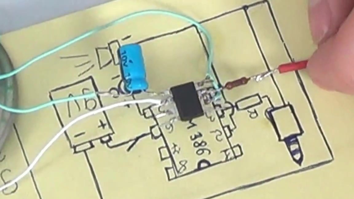
To the third foot on the left side, that is, the one between the previous two, we must solder the resistor.
We solder the wires to the second leg of the resistor, which will go to the positive contact on the mini jack.

We disassemble the mini jack. On the mini-jack, which the author uses, there are two contacts - on the left and right channels. They need to be connected together and soldered to the wire coming from the resistor to the contacts.
The minus or the mass from the jack must be soldered to the negative contact on the speaker.
In conclusion, it remains to solder the minus from the crown connector to the minus on the speaker.
After such simple manipulations, you can get a very effective amplifier, which we will use to make a portable speaker for a tablet or smartphone.