

How to make a full-fledged power supply yourself with an adjustable voltage range of 2.5-24 volts, it’s very simple, everyone can repeat without having amateur radio experience.
We’ll make it from the old computer power supply unit, TX or ATX, it doesn’t matter, fortunately, over the years of the PC Era, every house has already accumulated enough old computer hardware and there is probably a PSU there too, so the cost price homemade will be insignificant, and for some masters it is equal to zero rubles.
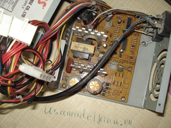
I got this AT block for alteration.
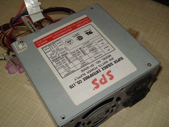
The more powerful you use the PSU, the better the result, my donor is only 250W with 10 amperes on the + 12v bus, but in fact, with a load of only 4 A, he can no longer cope, the output voltage completely sinks.
See what is written on the case.
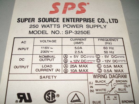
Therefore, see for yourself what current you plan to receive from your regulated PSU, donor such potential and lay right away.
There are many options for finalizing a standard computer PSU, but all of them are based on a change in the strapping of the IC chip TL494CN (its analogues DBL494, КА7500, IR3М02, А494, MV3759, M1114EU, MPC494C, etc.).
Fig. 0 Pinout of the TL494CN chip and its analogs.
Let's see a few options execution of computer power supply circuits, perhaps one of them will be yours and it will become much easier to deal with the harness.
Scheme number 1.
Let's get to work.
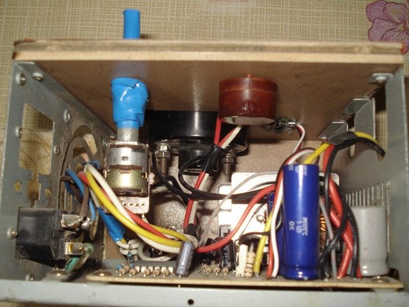
First you need to disassemble the PSU case, unscrew the four bolts, remove the cover and look inside.
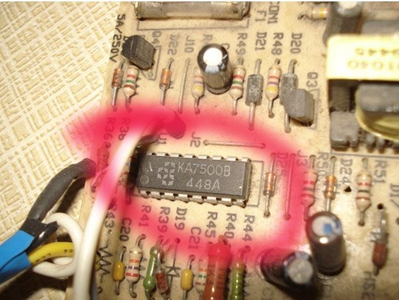
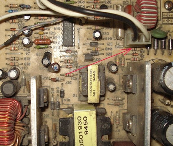
We are looking for a microcircuit on the board from the list above, if it doesn’t turn out to be, then you can look for a version of the revision on the Internet for your IC.
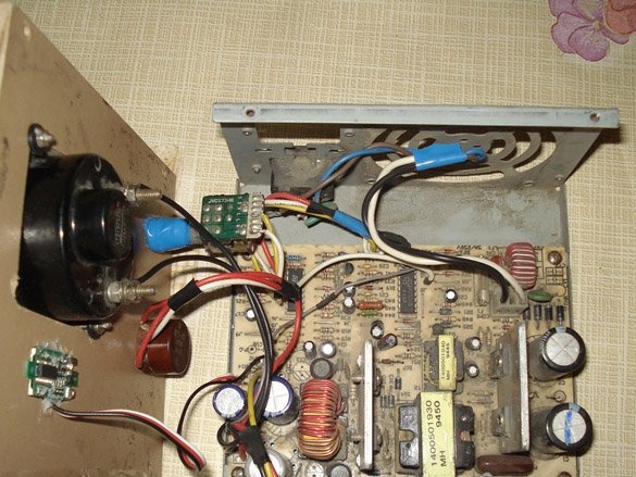
In my case, the KA7500 chip was detected on the board, so you can begin to study the strapping and the location of the parts that we do not need, which must be removed.
For ease of operation, first completely unscrew the entire board and remove it from the case.
In the photo, the power connector is 220v.
We disconnect the power and the fan, solder or bite the output wires so as not to interfere with our understanding of the circuit, we will leave only the necessary ones, one yellow (+ 12v), black (common) and green * (ON start) if there is one.
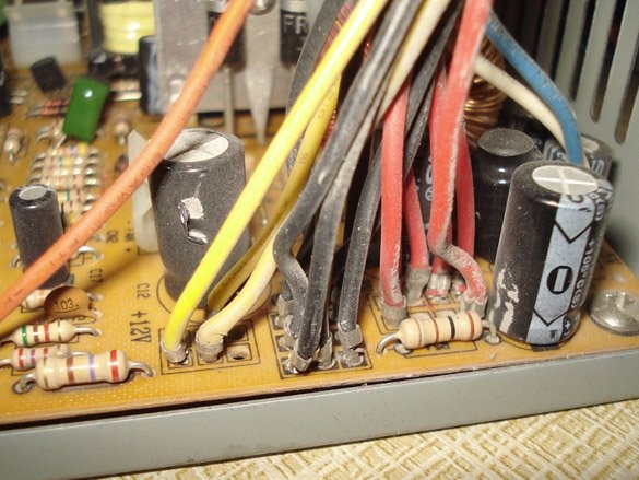
In my AT unit there is no green wire, so it starts immediately when it is plugged in. If the ATX unit, then it should have a green wire, it must be soldered to the "common", and if you want to make a separate power button on the case, then just put the switch in the gap of this wire.
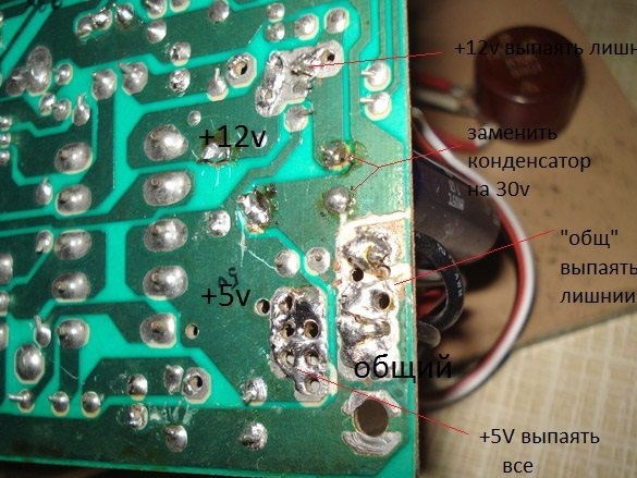
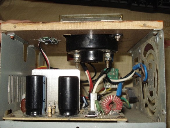
Now you need to look at how many volts the output large capacitors are, if less than 30v is written on them, then you need to replace them with similar ones, only with an operating voltage of at least 30 volts.
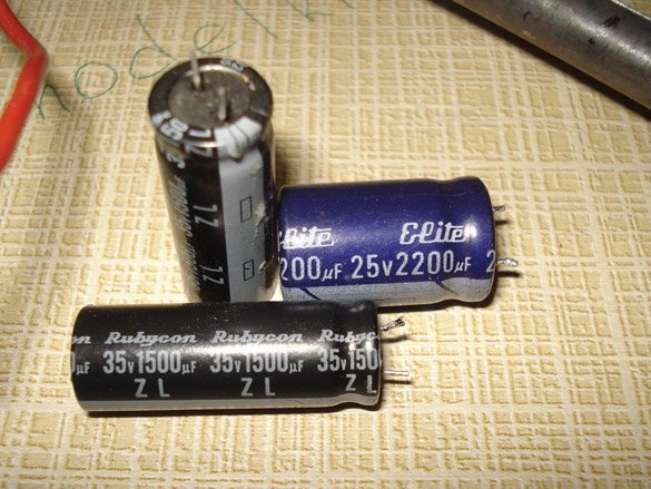
In the photo - black capacitors as a replacement option for blue.
This is done because our modified unit will produce not +12 volts, but up to +24 volts, and without replacement, the capacitors will simply explode during the first 24v test, after a few minutes of operation. When selecting a new electrolyte, it is not advisable to reduce the capacity, it is always recommended to increase the capacity.
The most crucial part of the job.
We will remove everything superfluous in the IC494 strapping, and solder the other values of the parts so that the result is such a strapping (Fig. No. 1).
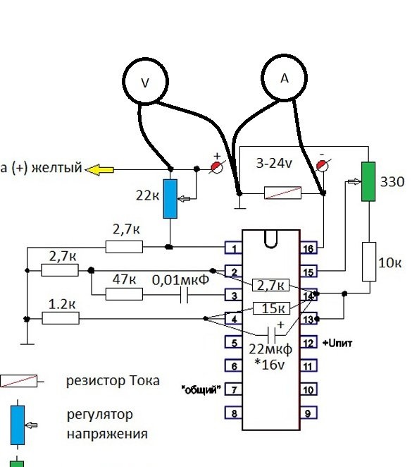
Fig. No. 1 Change in the strapping of the IC 494 chip (revision scheme).
We will only need these legs of the microcircuit No. 1, 2, 3, 4, 15 and 16, do not pay attention to the rest.
Fig. No. 2 Option for refinement on the example of scheme No. 1
Explanation of symbols.
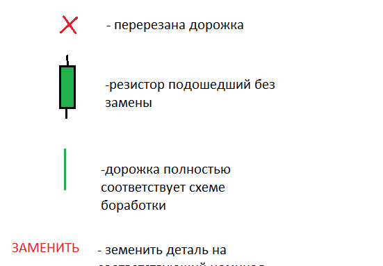
You need to do something like this, we find leg No. 1 (where the point on the case stands) of the microcircuit and we study what is connected to it, all the chains must be removed, disconnected. Depending on how the tracks will be located and the parts soldered in your particular modification of the board, the best option for refinement is selected, this may be soldering and raising one leg of the part (breaking the chain) or it will be easier to cut the track with a knife. Having decided on the action plan, we begin the process of alteration according to the revision scheme.
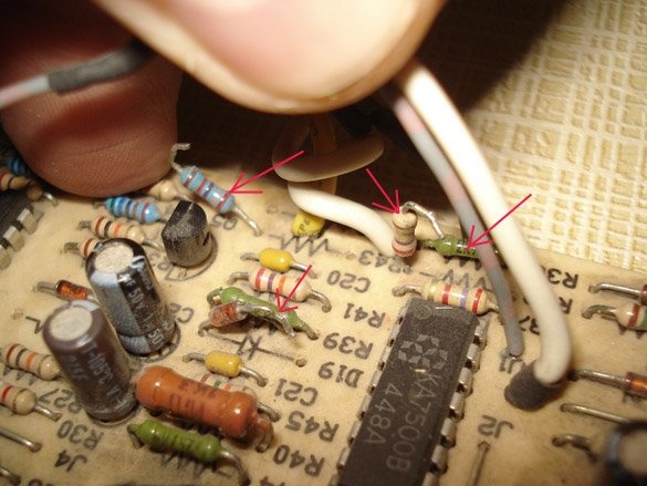
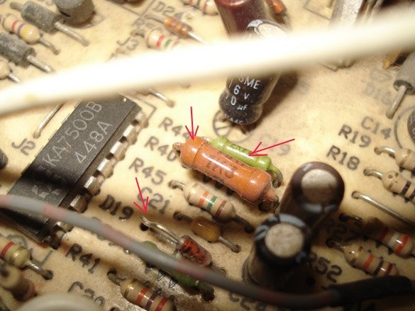
In the photo - the replacement of resistors to the desired value.
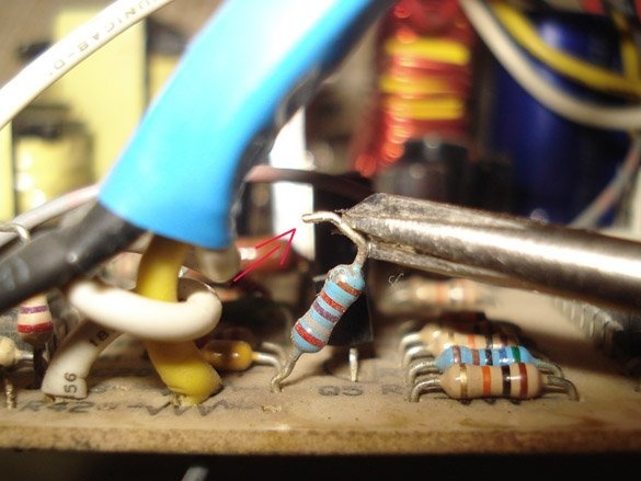
In the photo - raising the legs of unnecessary parts, we break the chains.
Some resistors that are already soldered into the strapping circuit may come up without replacing them, for example, we need to put a resistor at R = 2.7k with a connection to the "common", but there is already R = 3k connected to the "common", it suits us and we leave it there unchanged (example in Fig. No. 2, green resistors do not change).
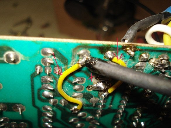
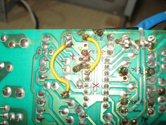
On the picture- cut tracks and added new jumpers, old values are written with a marker, you may need to restore everything back.
Thus, we look through and redo all the chains on the six legs of the microcircuit.
This was the most difficult point in the alteration.
We make voltage and current regulators.
We take 22k variable resistors (voltage regulator) and 330Ω (current regulator), solder two 15cm wires to them, solder the other ends to the board according to the diagram (Fig. No. 1). Install on the front panel.
Voltage and current control.
For control, we need a voltmeter (0-30v) and an ammeter (0-6A).
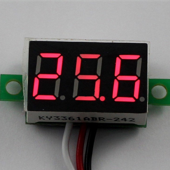
These devices can be purchased in Chinese online stores at the best price, my voltmeter cost me delivery of only 60 rubles. (Voltmeter:)
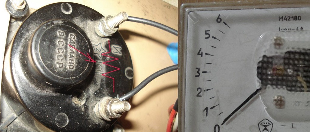
I used my ammeter, from the old reserves of the USSR.
IMPORTANT - inside the device there is a Current resistor (Current sensor), which we need according to the scheme (Fig. No. 1), therefore, if you use an ammeter, then you do not need to install a Current resistor, you need to put it without an ammeter. Usually, the R current is made home-made, a wire D = 0.5-0.6 mm is wound on a 2-watt MLT resistance, turn to the entire length of the coil, solder the ends to the resistance leads, that's all.
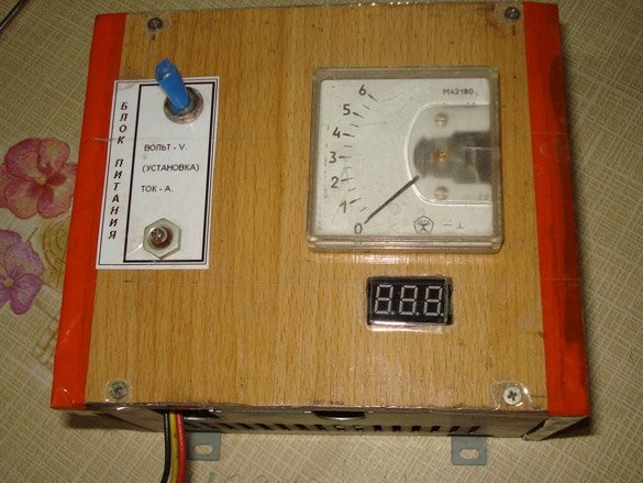
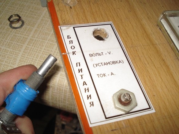
Everyone will make the case of the device for themselves.
You can leave completely metal by cutting holes for regulators and control devices. I used laminate trimmings; they are easier to drill and saw.
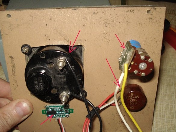
On the front plate we have devices, resistors, regulators, sign the designation.
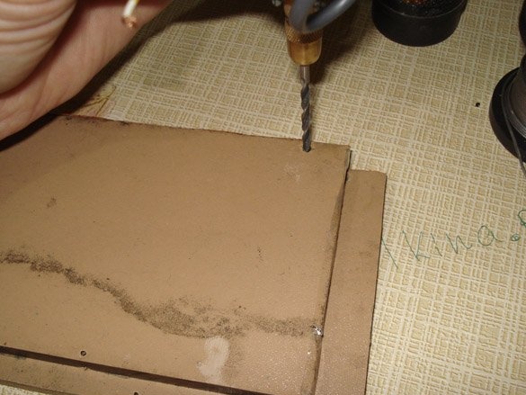
We make sidewalls, drill.
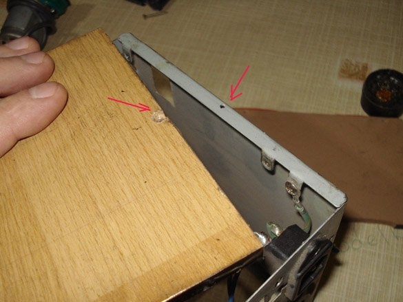
We drill mounting holes, assemble, fasten with screws.
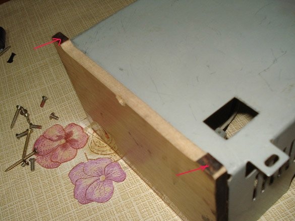
We get small legs when processing a laminate on a sharpener.
Assembled device, we will check what happened.
Let's see a little test.