» Electronics » Power supplies »Simple DIY do-it-yourself power supply

DIY do-it-yourself lab power supply


The laboratory power supply unit (BP) for the ham radio is an essential device! Have to work with different devices or their elements. Accordingly, there is a wide range of energy consumers and everyone has different supply voltages. There is nothing left but to get a ready-made PSU. But when I was asking the price of radio stores, I realized that it wasn’t so cheap and decided that for me, a simple, inexpensive power source would be enough for me. Since I can say, a beginner in this business, I first turned to literature, studied its working principle and want to tell you what is needed for this.

A simple laboratory BP scheme conventionally consists of two parts:
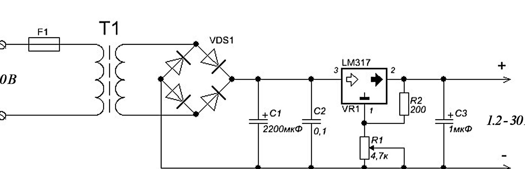
1) the PSU itself (transformer, diode bridge and capacitor) This is the main part, the power of the entire PSU depends on the choice of transformer parameters.
2) a small voltage regulator circuit (may be on a transistor or on a zener diode).
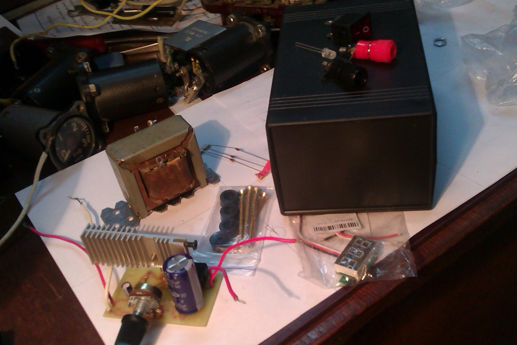

Required Items:
- transformer;
- Diode bridge;
- Zener diode __LM-317;
- Capacitors__C1 2200mkF, C2 0.1mkF, C3 1mkF;
- Resistors _____R1 4.7 kOm (variable), R2 200 Om;
- Voltmeter;
- Light-emitting diode;
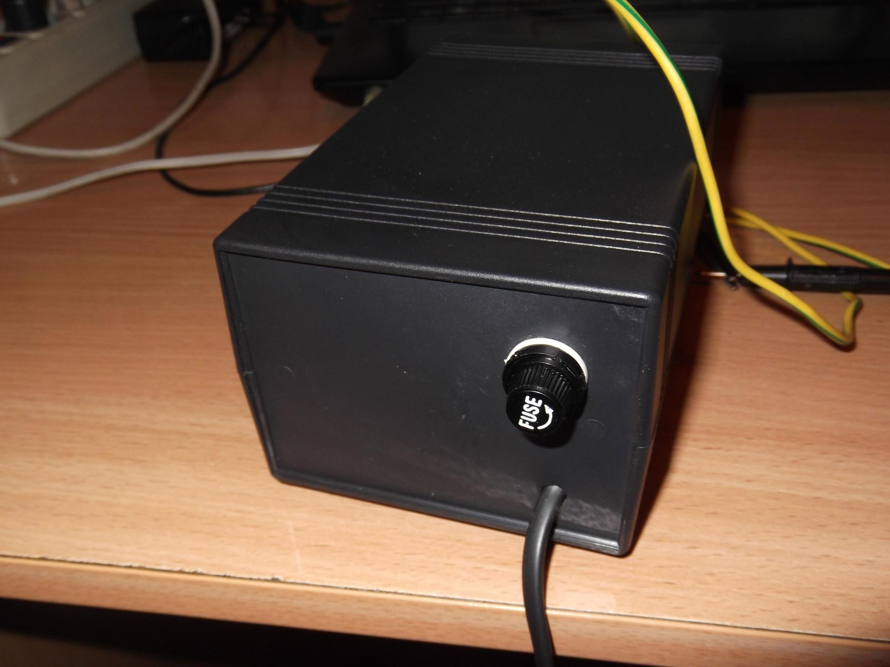
- fuse;
- Terminals;
- The radiator.

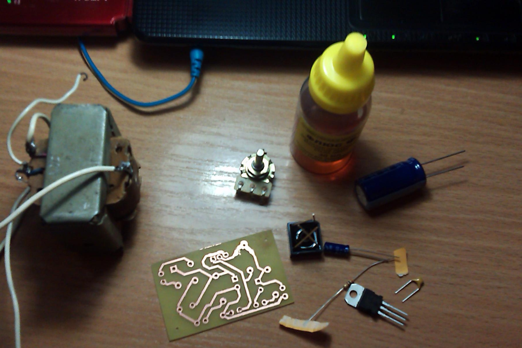
I already had a transformer (TS-10-1), I did not have to choose and spend money on this.

Once all the elements are already assembled, let's get started.

1st STAGE: We are preparing a board.
bp.rar [2.34 Kb] (downloads: 1830)


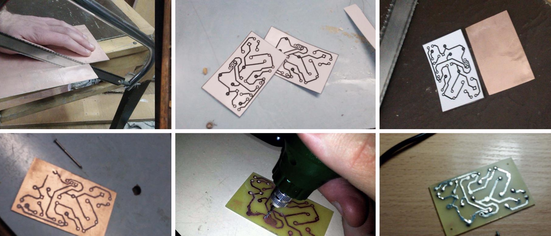
2nd STAGE: Solder the elements according to the scheme. If you don’t have the opportunity to “etch” the board, you can make it a “canopy”.

3rd STAGE: We connect the board to the transformer, and our PSU is ready.

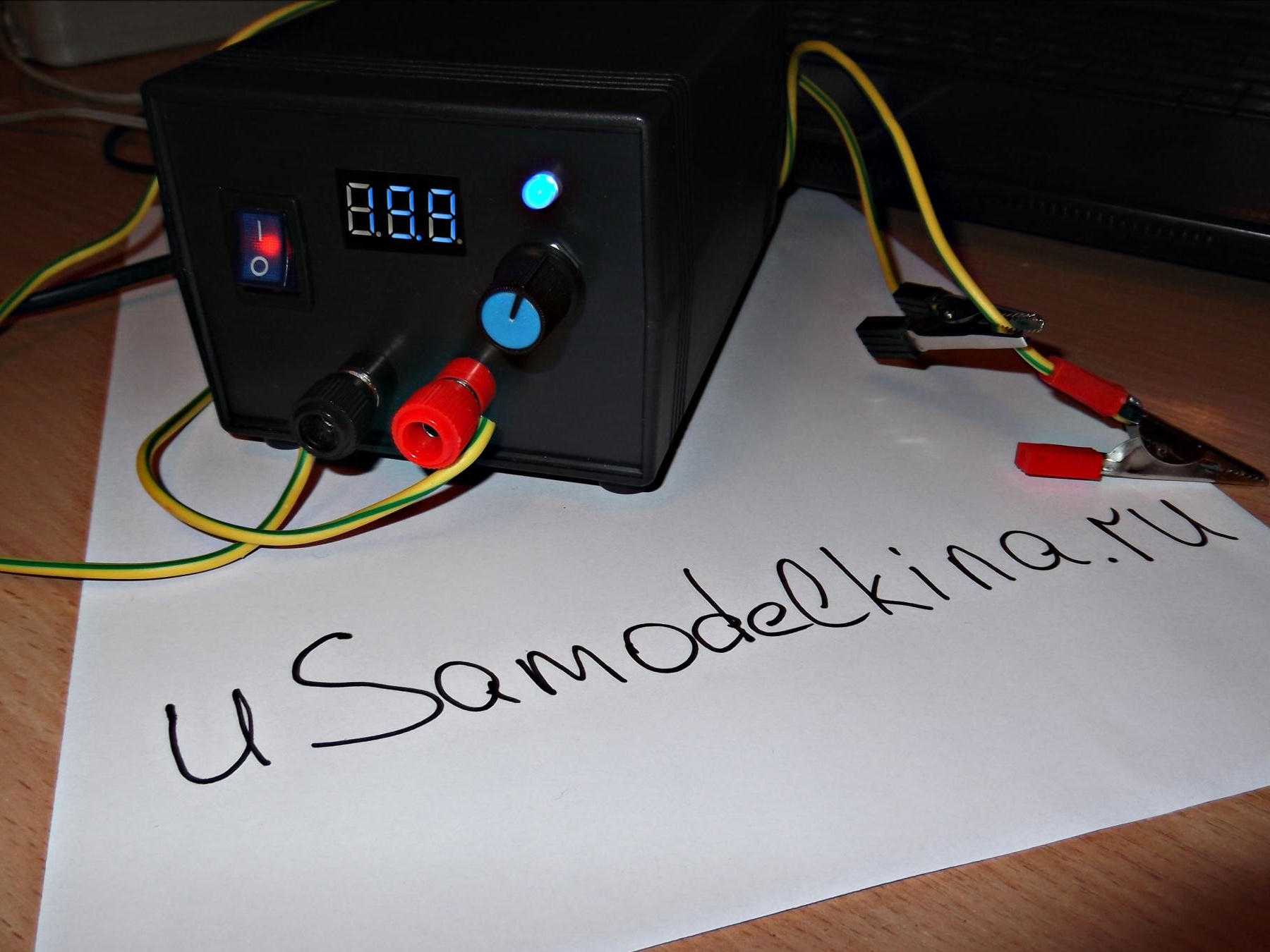
But now we need to make it so that it is beautiful and practical. For this, I purchased a case and a digital voltmeter.

We make installation in the case.

Using a drill and needle file, holes were made on the front panel. The voltmeter "sits" on two droplets of superglue.

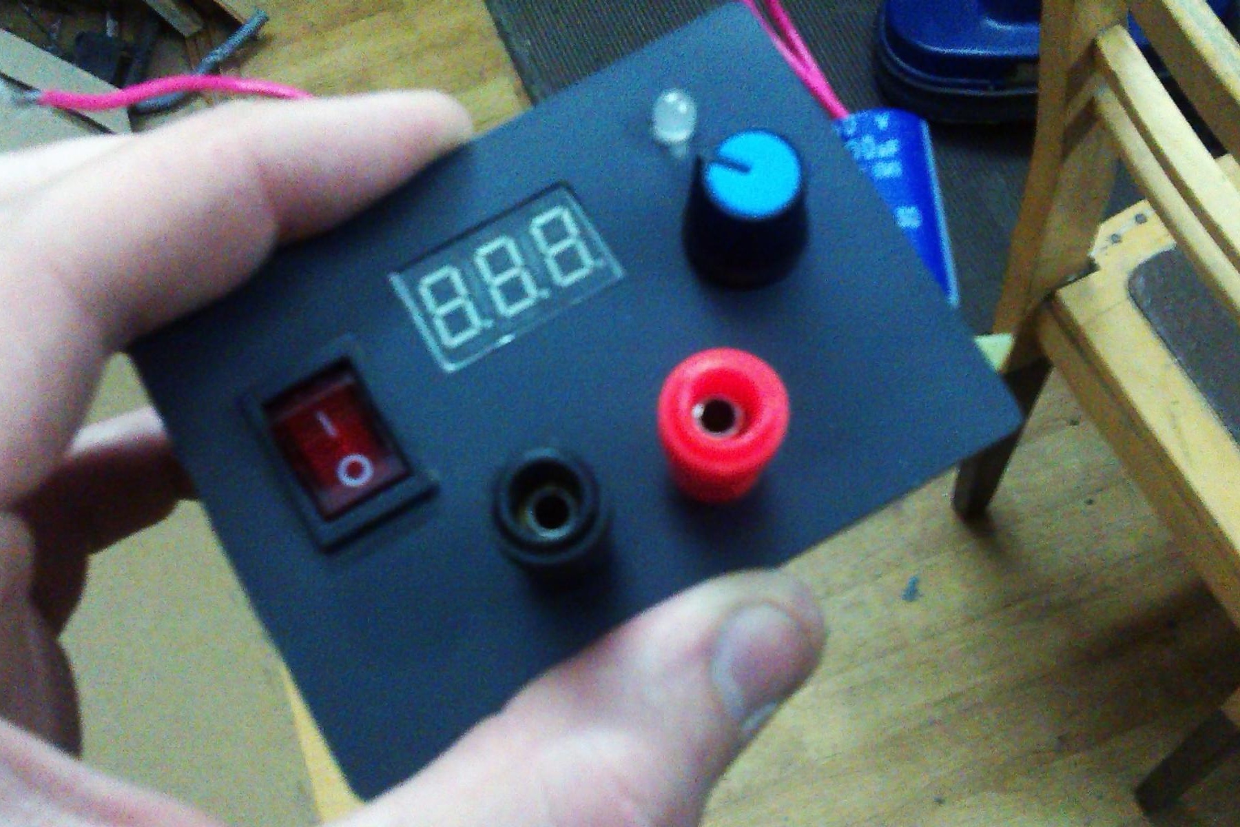
A few hours later I got the desired result.


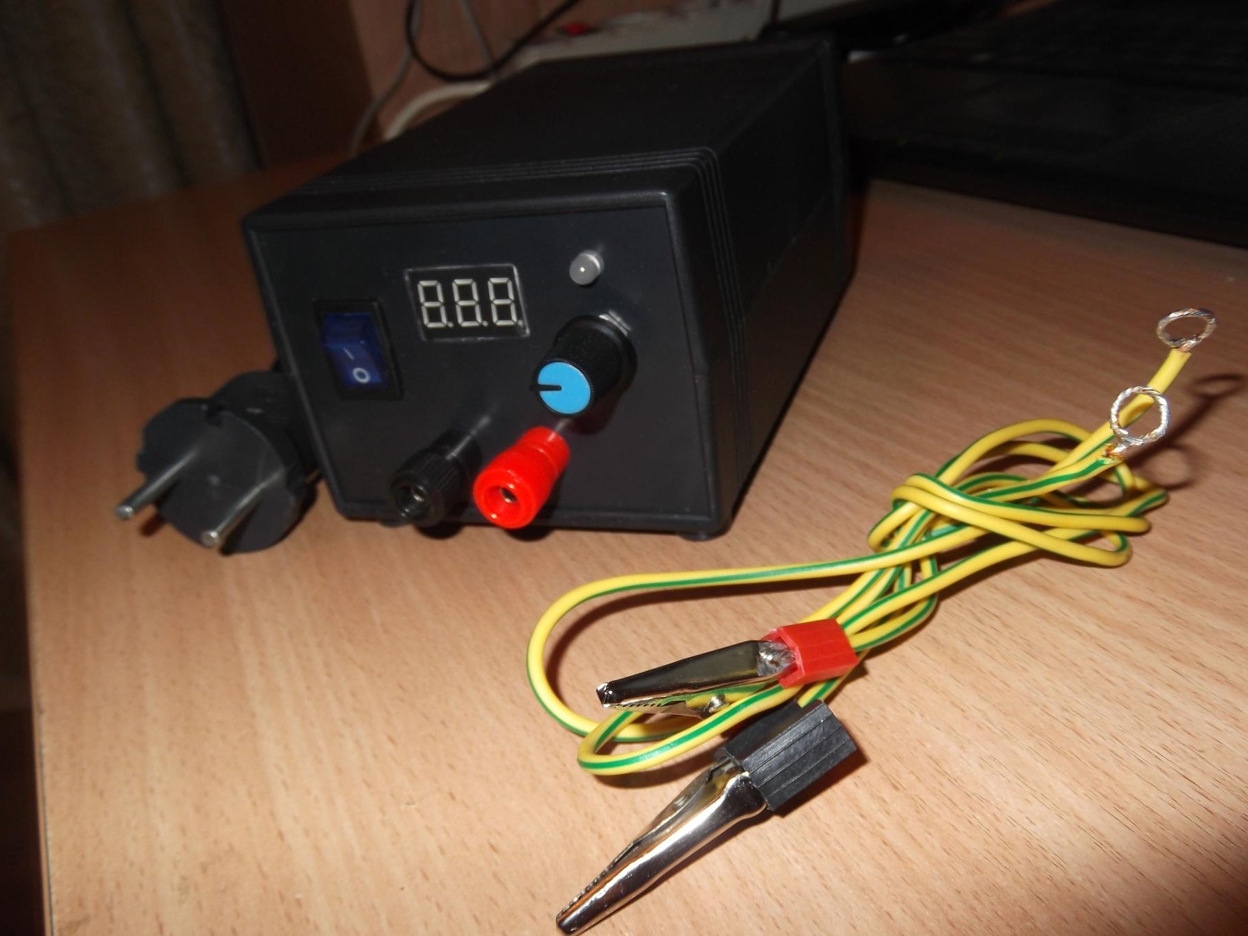
Now I have a power source that very often helps me out.
8.5
8.7
9.8

Add a comment

    • smilesmilesxaxaokdontknowyahoonea
      bossscratchfoolyesyes-yesaggressivesecret
      sorrydancedance2dance3pardonhelpdrinks
      stopfriendsgoodgoodgoodwhistleswoontongue
      smokeclappingcraydeclarederisivedon-t_mentiondownload
      heatirefullaugh1mdameetingmoskingnegative
      not_ipopcornpunishreadscarescaressearch
      tauntthank_youthisto_clueumnikacuteagree
      badbeeeblack_eyeblum3blushboastboredom
      censoredpleasantrysecret2threatenvictoryyusun_bespectacled
      shokrespektlolprevedwelcomekrutoyya_za
      ya_dobryihelperne_huliganne_othodifludbanclose
7 comments
Three years have passed. Is the device still working? No changes were made?
- Zener diode __LM-317;
This is not a zener diode:
"The chip has been a hit among beginner hams for decades, thanks to its simplicity and reliability. Based on this chip, you can assemble an adjustable power supply on the LM317, a current regulator, an LED driver and other power supplies." ... "Provides an output voltage of 1.2 up to 37 V.
Load current up to 1.5 A.
Availability of protection against possible short circuit.
Reliable protection against overheating. "
You need to be more precise ...
The conclusion is not a change to make: it is possible. If not mistaken, Volt 15-18 will be. In order to regulate the change, it would be good to make taps from the secondary winding, otherwise it is stupidly powerful with variable resistance, but why do you need to adjust the change?
Amperage can be increased by rewinding the secondary with a thicker wire, if you find another way to unsubscribe, I also want naefool physics :).
If you look at the cross-section of the TC10 winding in the reference book, then in my opinion a maximum of half an ampere can be pulled from it, otherwise it will get very hot. But in general, a very beautiful and neatly made block. True, in my understanding, a "laboratory" PSU is something closer to LATRA :)
Hello, please tell me, is it possible to draw more conclusions on the break? Those. Before reaching the diode bridge, throw 2 wires and there will be a change? How many volts, 30? And what else to regulate the change, what elements are needed?
And the second question: how to increase amperage?
alexx455
Well, in this circuit, the current is limited to lm 317 - it pulls a maximum of one and a half amperes on the datasheet. and the transformer is clearly not more than an ampere.
It would be nice to add to the description such a parameter as the limiting current of this PSU !!!

We advise you to read:

Hand it for the smartphone ...