
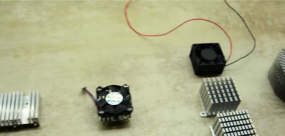
The home-made driver, the manufacture of which this material is devoted to, will allow us to regulate the lighting of LED strips, lasers, computer fans.
Let's start by watching the author’s video on making a driver
We will need:
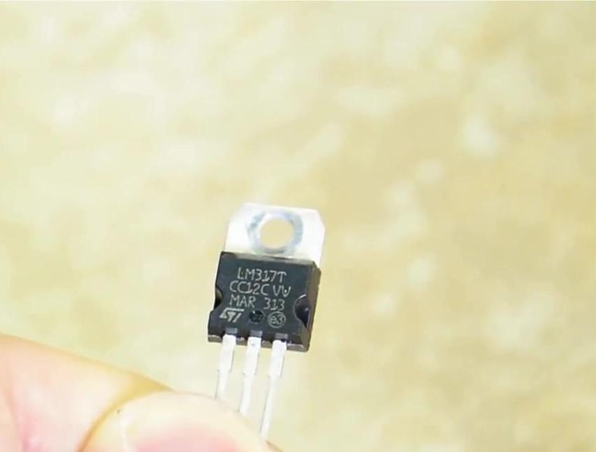
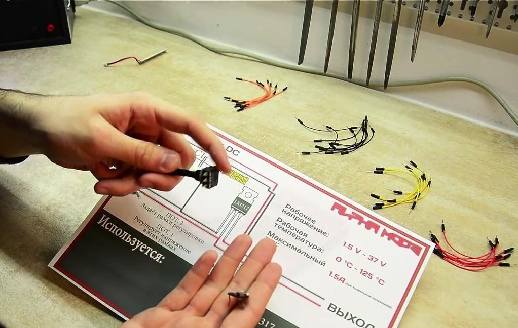
- stabilizer LM317T;
- potentiometers at 470 ohms;
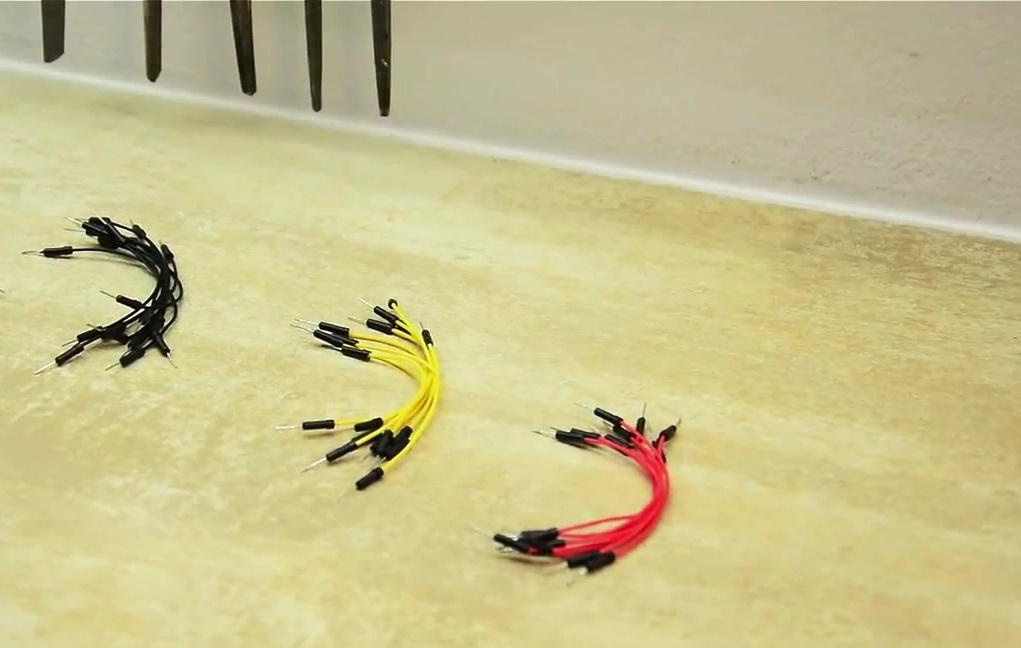
- wires;
- capacitor.
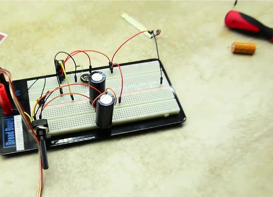
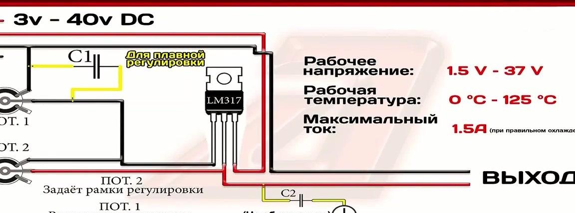
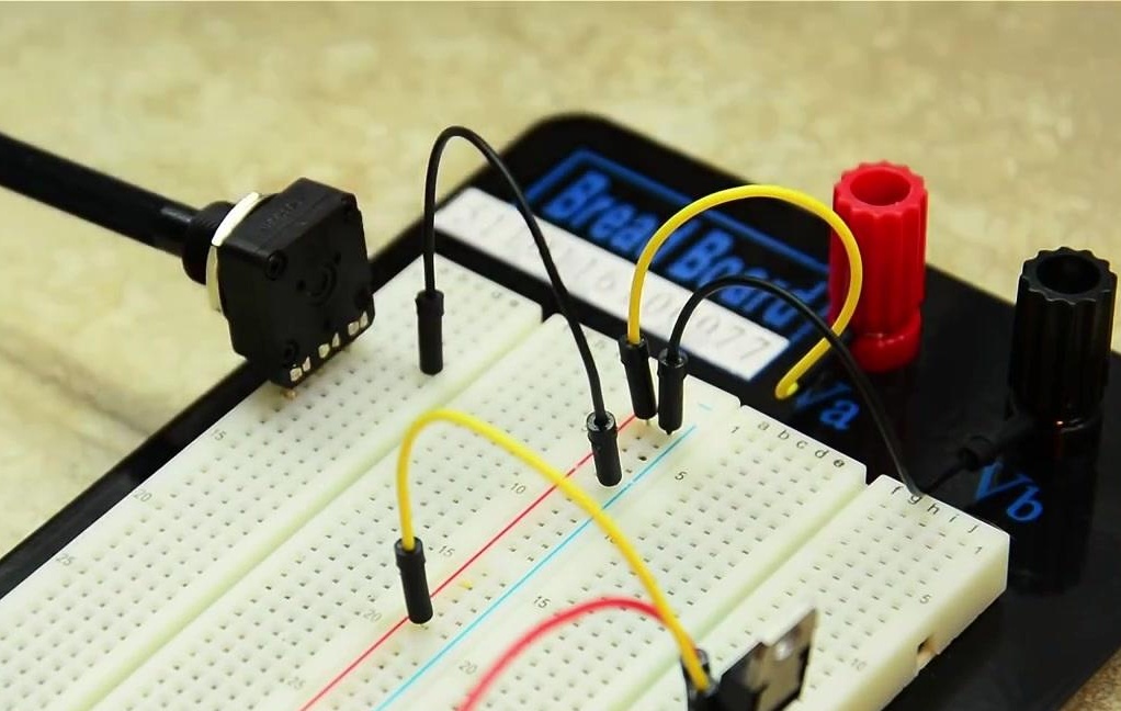
To present the assembly in a more understandable way, the author of the idea collects everything on the Bread Board. Introducing the assembly diagram.
We clarify that the potentiometer number 2 is used only when it is necessary to assemble the board. When the assembly result is satisfactory, it is necessary to replace the potentiometer with a resistor of the same resistance, otherwise there is a likelihood that the potentiometer simply burns out.
We offer to test the assembly on the LED, which consumes 3 volts. The input voltage will be 12 volts, which the stabilizer must convert into three so that the LED does not burn out.
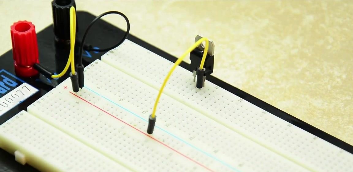
We insert the stabilizer on the board and connect the power to the rightmost foot.
The stabilizer output is on the central foot. We also connect a wire to it.
The first potentiometer operates within the scope set by the second potentiometer. This means that if 5 volts are set in the second potentiometer, then the first will regulate from 1 to 5 volts. According to the scheme, the minus passes through the first potentiometer and falls on the leftmost leg of the stabilizer.
Plus, from the middle output of the stabilizer, it gets to potentiometer number two, from which a small current hits the minus of the input. Here, the author advises experimenting with the resistance of potentiometers to obtain the best effect.
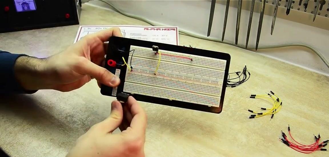
It remains to connect the capacitors, which are marked on the diagram as C1 and C2. The author does not use the second capacitor in his video, but he prefers to set the first as an example of work.
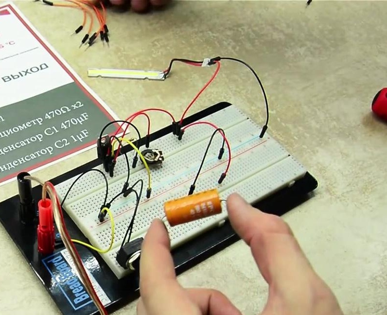
Now we connect to the plus of the output what we want to regulate. We also connect the main minus to it.
The trimer, which the author uses as the first potentiometer, is a variable resistor, and the LED is very sensitive to voltage, so it is almost impossible to obtain smooth adjustment.For this you need to use a capacitor.
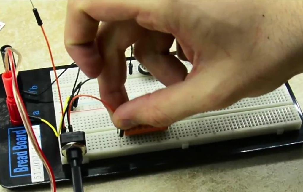
We connect the capacitor to the input and output of the first potentiometer.
According to this scheme, you can make a miniature manual searchlight.