» Electronics » Sound and Acoustics »Home-made sound amplifier on the chip TDA7375

Homemade TDA7375 Chip Sound Amplifier

Homemade TDA7375 Chip Sound Amplifier

Good day to all the residents of our sites.

It is known that music plays a big role for a person, it was on the basis of this thought that an attempt was made to assemble a sound amplifier that could produce decent sound.

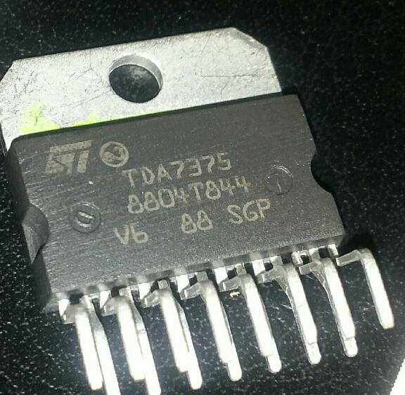
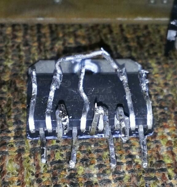
So, for starters, we need patience, straight arms and curved gyrus, as well as tools and components for the amplifier. The chip itself can be purchased at the radio store. At the moment, it costs about 150 rubles. Actually, here she is.

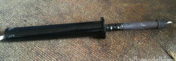
You will also need a soldering iron with a capacity of about 30-40 watts.

Solder. A tin-lead alloy of 60% -40% is better.

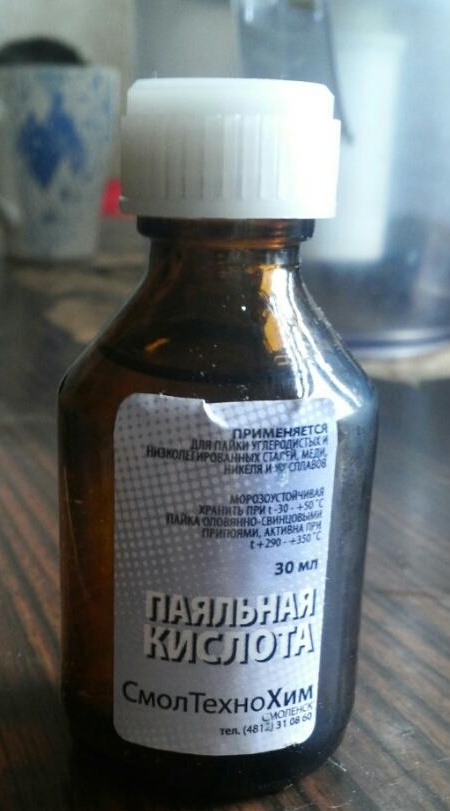
Soldering is best with soldering acid. The wires are immediately tinned without any
difficulties.

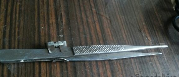
Amplifier assembly tweezers to hold the resistor and capacitor when soldering. They also need to bend the legs of the chip.

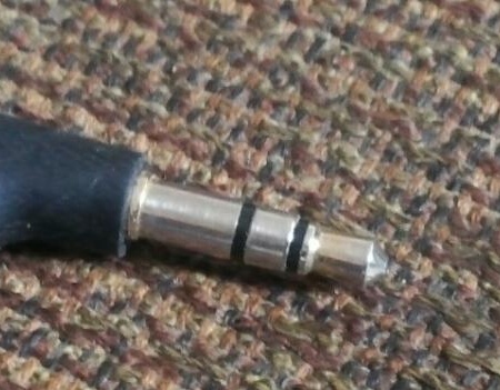
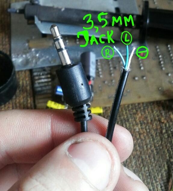
The sound input will be a 3.5 mm jack connector. Since the amplifier is two-channel, this plug is just right.

With thermal paste, the microcircuit will be better cooled, transferring heat to the entire surface. In this case, I used KPT-8.

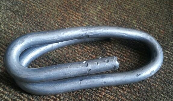
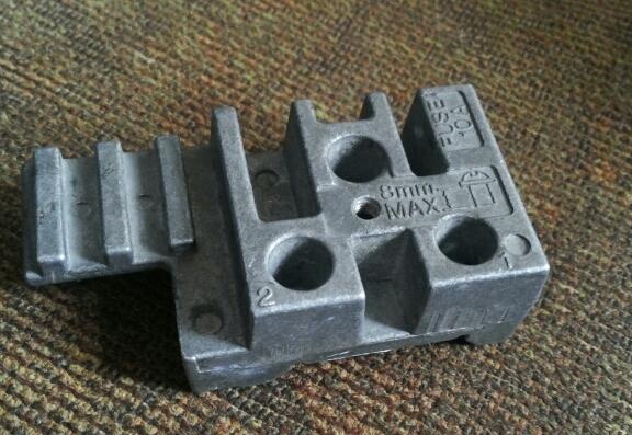
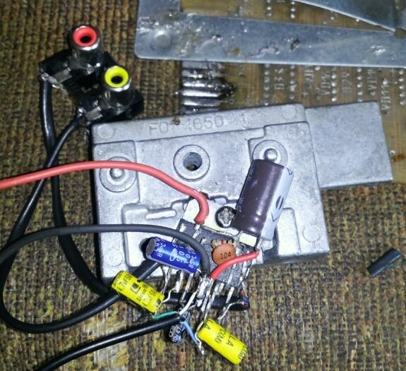
The amplifier will be mounted on this radiator. The bigger, the better. Since the circuit is quite hot, you will need capacitors, one resistor (all markings are visible in the photo), a resistor with a resistance of 10 kOhm.


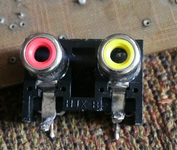
To connect the sound will be a connector to two tulips.

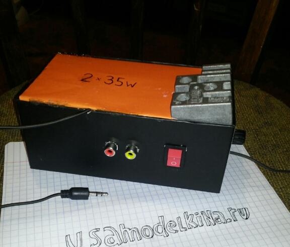
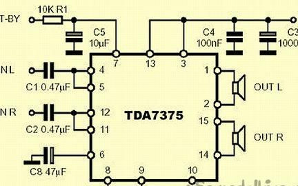
Well, all the components are ready, you can start assembling. The amplifier circuit was taken from the Internet. The amplifier has an output power of 35 watts for two outputs and a load of 4 ohms.

Assemble the amplifier can be mounted.

First of all, carefully unbend the legs of the microcircuit. For the convenience of soldering, we do it with tweezers.

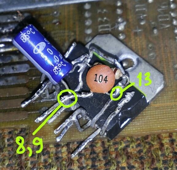
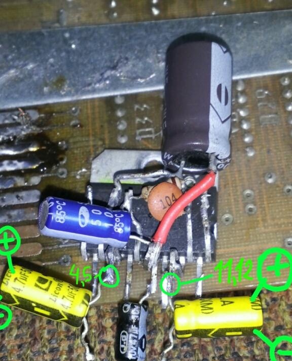
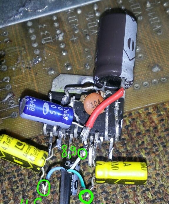
Then you need to solder 4 and 5, 9 and 8.11 and 12 legs of the microcircuit together.

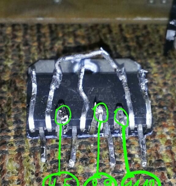
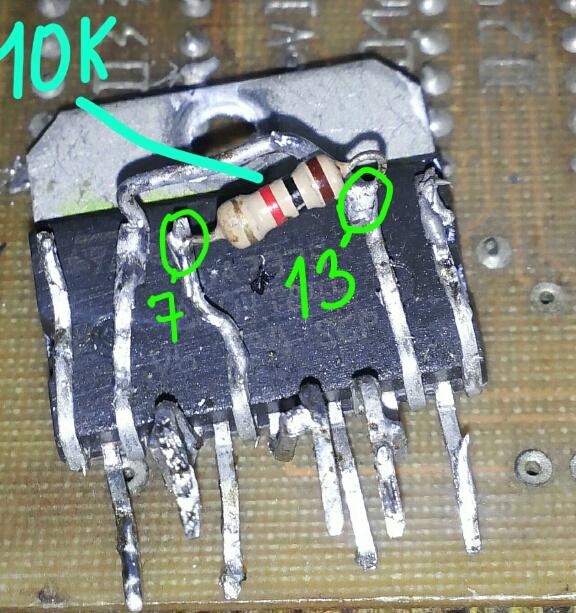
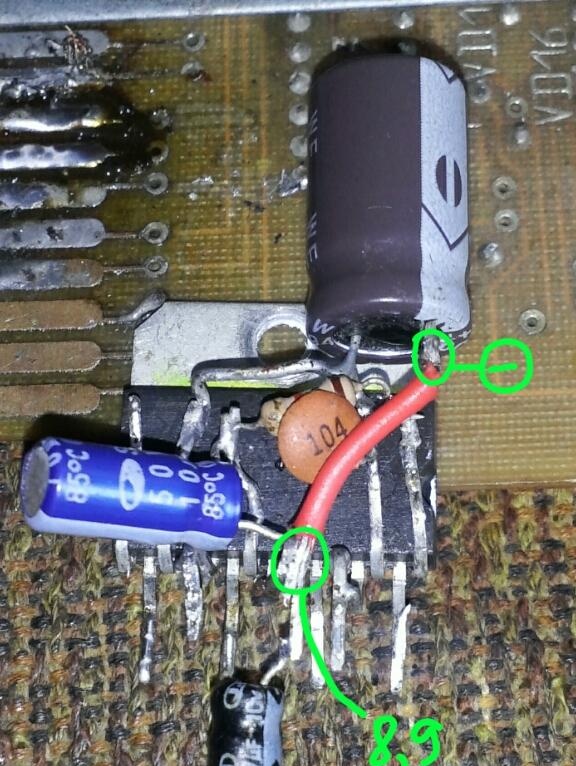
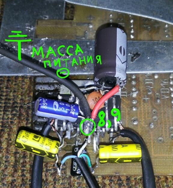
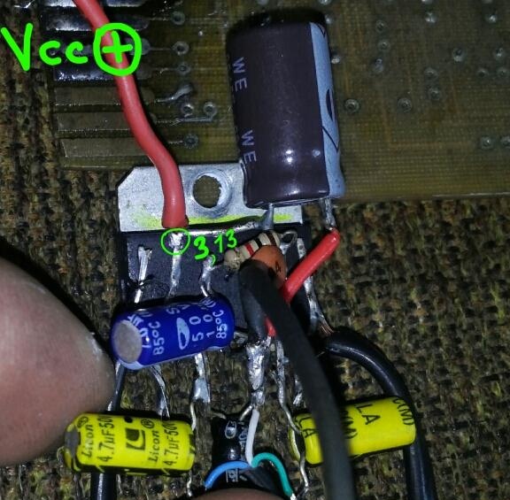
3 and 13 legs are plus power, solder them with wire.

Between the 7th and 13th legs we solder a 10 kOhm resistor.

To the leg 7 plus solder the capacitor to 10 microfarads. Its other end is to 8.9 legs. To the 8.9th leg of the microcircuit, we put a dry capacitor with the marking 104, connected to the 13th leg.


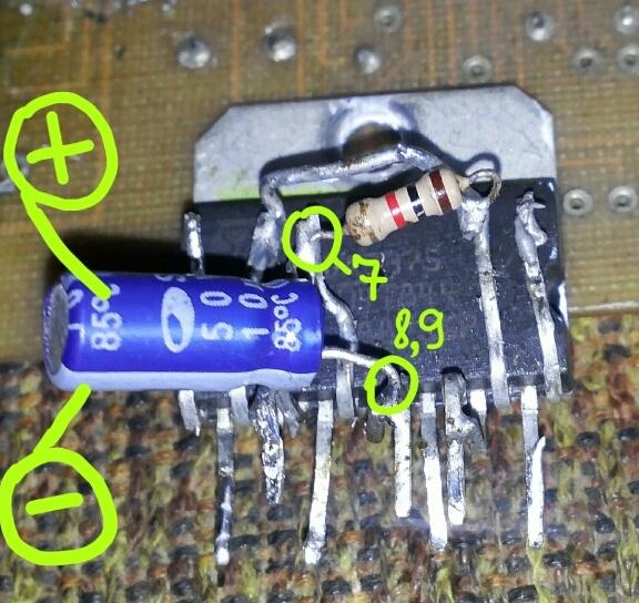
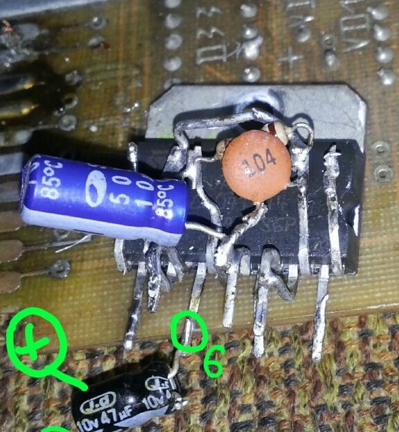
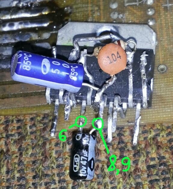
To the 6th leg, a capacitor for 47 microfarads, connect its minus with 8 and 9 foot microns.


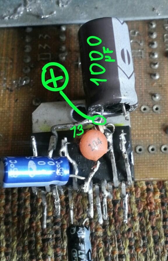
Now you need to put the power filter (this is a capacitor for 1000 microfarads), plus it is soldered to the 13th leg, and minus to 8 and 9.


The sound filters are 4.7 mF capacitors. Plus, each of the two goes to the 4th, 5th leg, the other capacitor to the 11th, 12th leg.

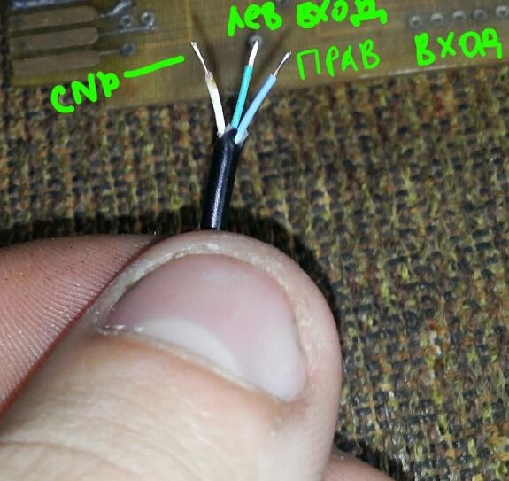
The next step: soldering the sound input (the plug itself). White is a minus, the other two wires are responsible for stereo mode, that is, the left and right inputs.Pre-tinning the wires, we solder to the conders.


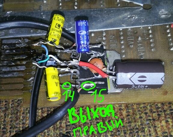
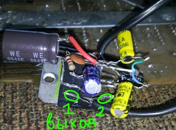
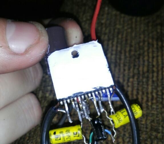
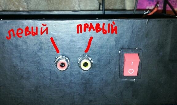
Then it remains to solder the sound outputs, there are two, plus and minus power and arrange it all in a box. It is necessary to coat the back of the microcircuit with thermal grease with a thin layer and fix it to the radiator.


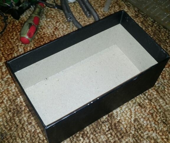
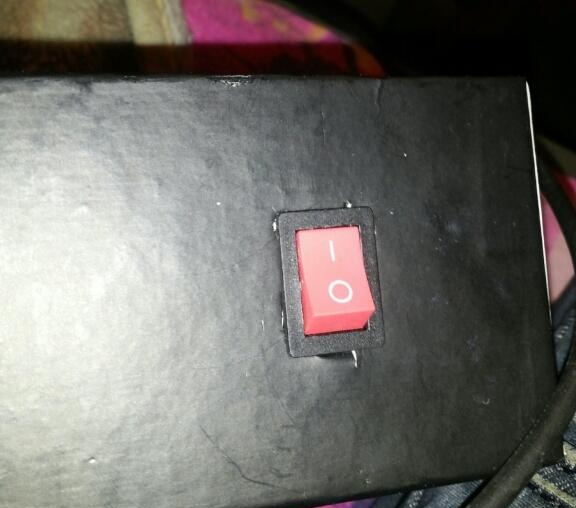
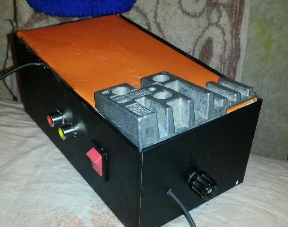
Now the final, cosmetic phase. We create the case, the basis was a black cardboard box.

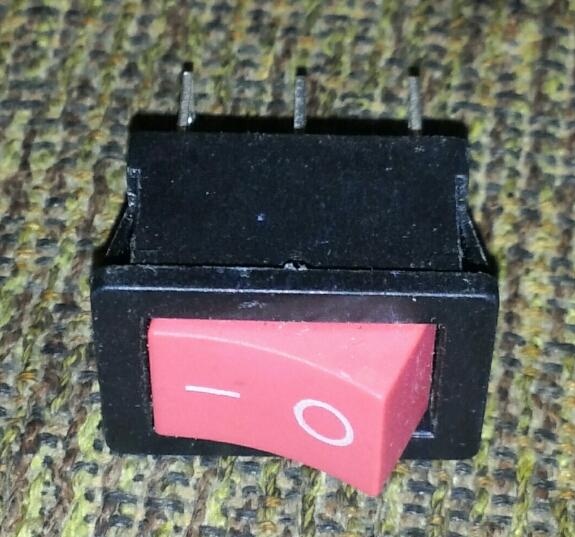
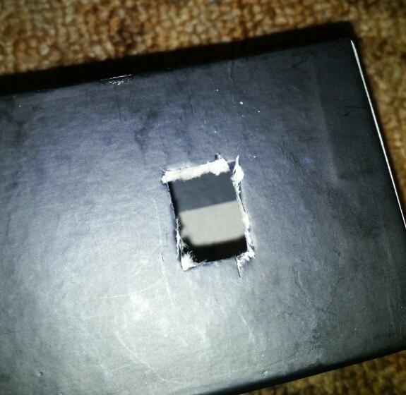
Cut a hole for the switch with a clerical knife on the front of the case.


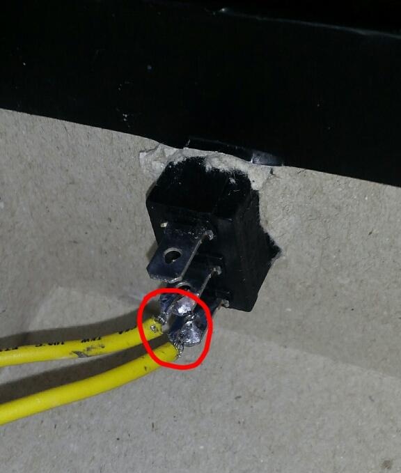
On the reverse side, solder two wires to the lower contacts of the switch.

At the front of the case we have sound outputs for connecting tulips. On the reverse side we fix with hot glue.


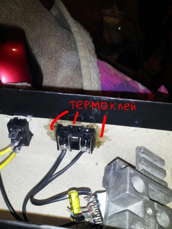
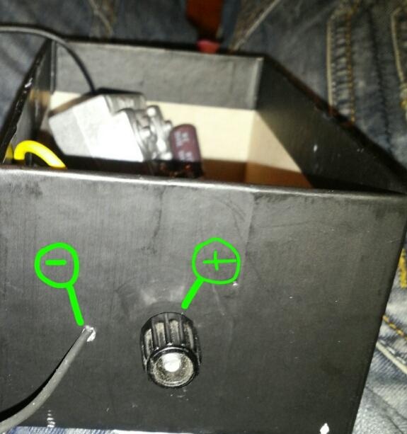
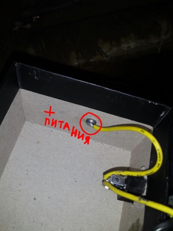
We take out a clip on the side for connecting the power plus and a black wire (ground).


On this, the amplifier is almost ready, it remains only to close everything on top with a lid, after having previously measured the dimensions. After the lid is fixed to hot melt adhesive.

Such an amplifier is suitable for home use, as well as in car.

The amplifier can be powered either from a computer power supply or from a car battery. Everyone enjoy listening to music.
2.6
2.8
1.1

Add a comment

    • smilesmilesxaxaokdontknowyahoonea
      bossscratchfoolyesyes-yesaggressivesecret
      sorrydancedance2dance3pardonhelpdrinks
      stopfriendsgoodgoodgoodwhistleswoontongue
      smokeclappingcraydeclarederisivedon-t_mentiondownload
      heatirefullaugh1mdameetingmoskingnegative
      not_ipopcornpunishreadscarescaressearch
      tauntthank_youthisto_clueumnikacuteagree
      badbeeeblack_eyeblum3blushboastboredom
      censoredpleasantrysecret2threatenvictoryyusun_bespectacled
      shokrespektlolprevedwelcomekrutoyya_za
      ya_dobryihelperne_huliganne_othodifludbanclose
12 comments
well done, everything is simple, understandable for any dummies, but here they immediately barked ... you can rinse the acid in a soda solution ...
"So, for starters, we need patience, straight arms and curved gyrus." Can you tell me, by chance, how do I measure the curvature of my gyrus? And then it seemed to me that they turned around and wrapped in the opposite direction! I will not say anything about the author’s “even hands”. Sadly somehow ...
Description to match the installation:
Since the circuit is quite hot, you will need capacitors, one resistor
xaxa
Sawing while watching it all, itching in the most unexpected places ... For such an installation of this high-tech 3D product, the aftar soldering iron should be in another place, along with the soldering acid. PPC went craftsmen ...
P.S. Installation by a specialist for car use, especially the case =)))
Yes gentlemen, you have strained with humor. A poor indicator, then with the rest of it.
pardon
And I liked it! yes
Smart rationale ...
"It is known that music plays a big role for a person, it was on the basis of this thought that an attempt was made to assemble a sound amplifier that could produce decent sound."
High technology.

The original design ...


Envy silently.
Happy April 1st!
blum3
.Voltage not lower than supply voltage, capacity not 47 MF, and from 47 microfarad and higher. And, of course, do not install in any case according to the above description!
and if there is no capacitor on 10V 47mF which can be replaced
a rare pervert. a board ready together with mikruha weakly takes a penny! As for the acid, it immediately becomes clear that the soldering info was taken from yard or garage basils: belay: .a photo of a type of wall mounting should be done to the department inappropriately. Capitan_Veshdoki and about the power of the soldering iron you are wrong with me when the 20 wadding was covered with a soldering weave with small modifications and nothing overheated. the point is not in power but in the time of thermal contact.
Capitan_veshdoki
I have never seen such perverts. To begin with, the soldering acid corrodes the legs of the board - the worse the rosin is - it’s not clear. I solder the POS solder with liquid rosin - it splashes and “grabs” everything with a bang, I just need to be able to. The second - who solders 60-W integrated amplifiers with a soldering iron ?! It overheats and accordingly overheats the board. (I remind you that the maximum solder temperature for this microcircuit is 260 degrees, and even then within 10 seconds) Anyway.Soldering this whole thing can at best be done on a mock-up, or fixing conclusions on cardboard - you cannot dispose of everything in such a crowd, close something sooner or later, and the temperature dissipates worse.
yyy
hands tear for such an installation
Of course, you will excuse me, but it is impossible to solder the radio parts (with soldering acid) since its remnants will corrode the contacts and as a result, over time, the product will start to work incorrectly or even completely fail.

We advise you to read:

Hand it for the smartphone ...