

Spring is so much in this word! It's time to work in the yard, at the cottage, garden and vegetable garden, well, how can you manage without good music, so let's make a gardencountry (whoever wants it, call it) the music center do it yourself.
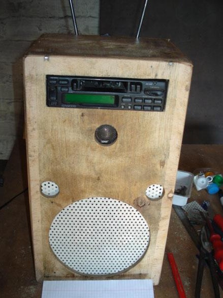
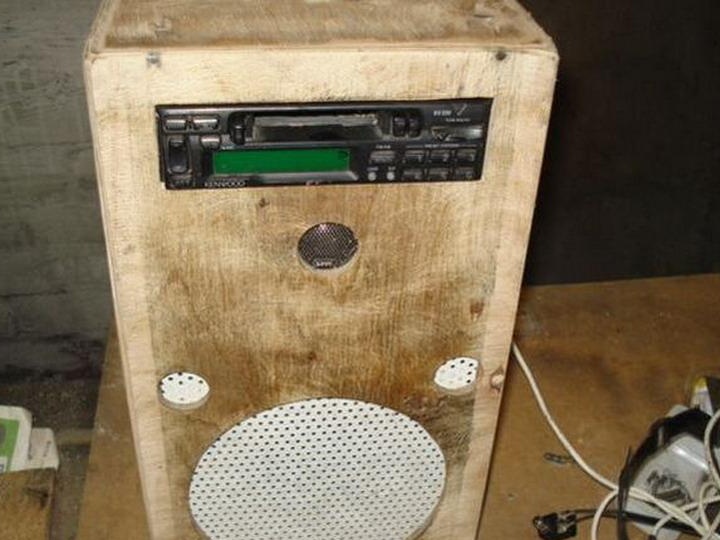
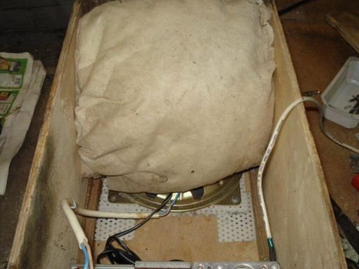
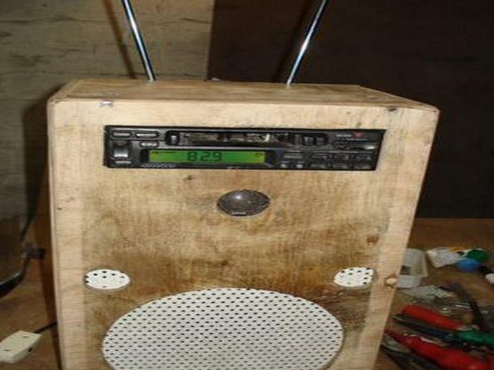
In the photo: Appearance, intermediate manufacturing stage.
ITEM 1. Let's get started.
What do we need for this:
- An old but still working passive speaker, medium size
- Old cassette player
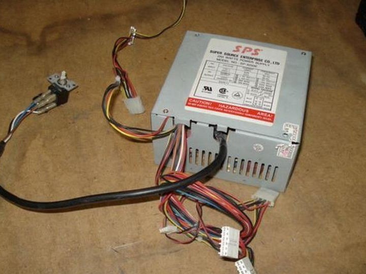
- Old power supply from AT or ATX computer
- A small shielded audio cable with a mini 3.5 jack at the end
- Power cord with 220v plug.
Instruments:
- Electric drill
- Electric fret saw
- Bulgarian
- Glue on wood.
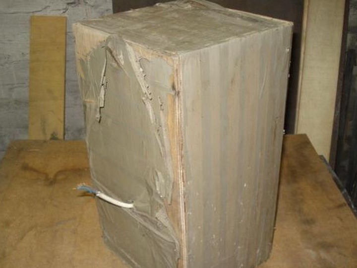
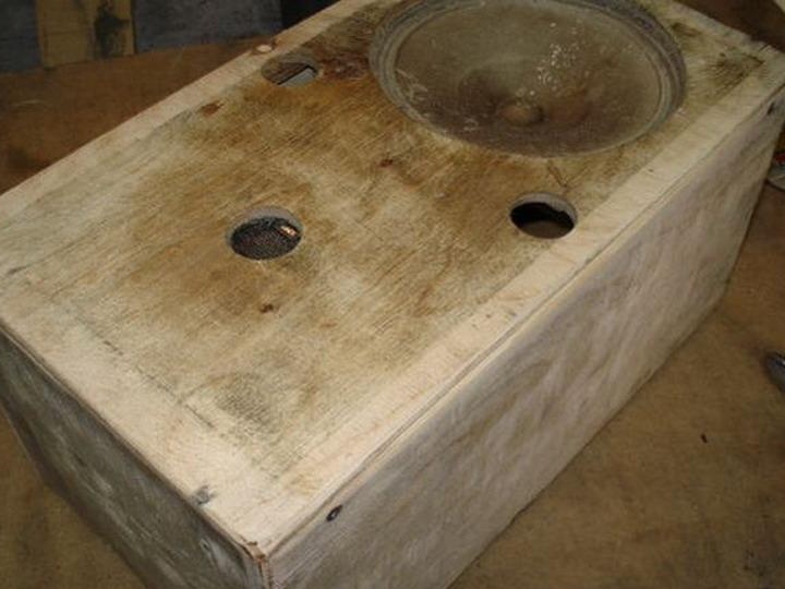
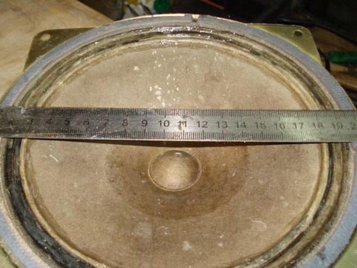
I will remodel my old home-made speaker, which has worked and lived on the street for many years, now it's time to upgrade it.
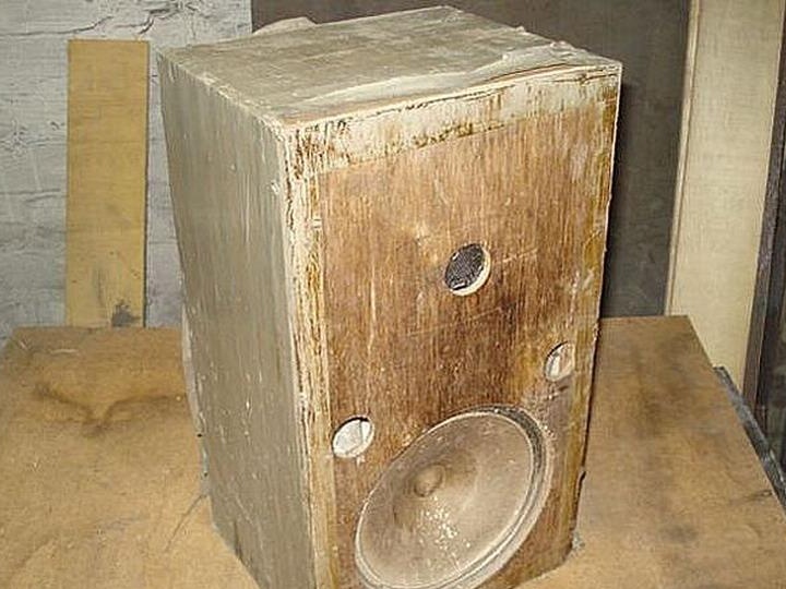
In such a terrible form, she appeared on a workbench.
POINT 2. Electronics.
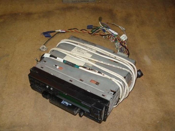
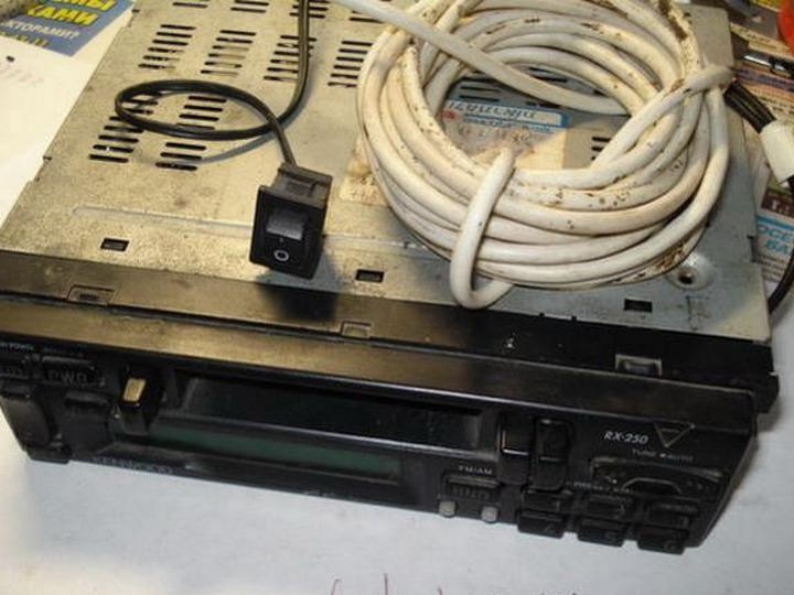
For the heart of the music center, the old cassette car radio is well suited, which probably lay in the garage every motorist.
We will adapt the most universal and widespread PSU in the world for power supply, this is the power supply from any PC system unit, which everyone who visits the site of the masters of masters has 100%.
To begin, let's refine our car radio with an external audio input, thanks to which it can proudly be called a Multisystem, we can connect any mobile device, gadget with wi-fi to listen to a huge number of Internet radio stations.
First, let's take apart the radio and solder the shielded audio cable with a mini jack 3.5 at the end, to which our modern friend’s phone, tablet or other device that has a headphone jack on its board will connect.
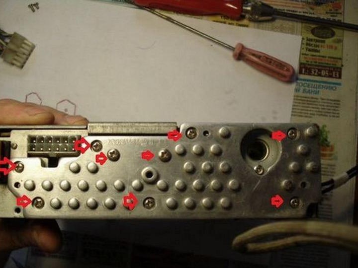
Unscrew all the necessary bolts and remove the upper housing cover.
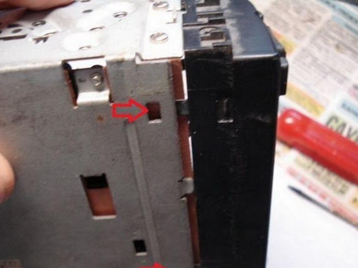
Unscrew the side four bolts.

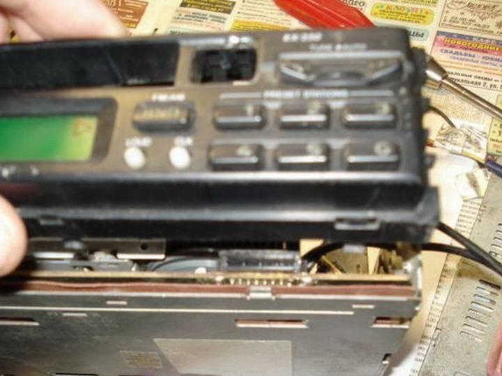
Pressing the plastic locks with a screwdriver remove the front panel.
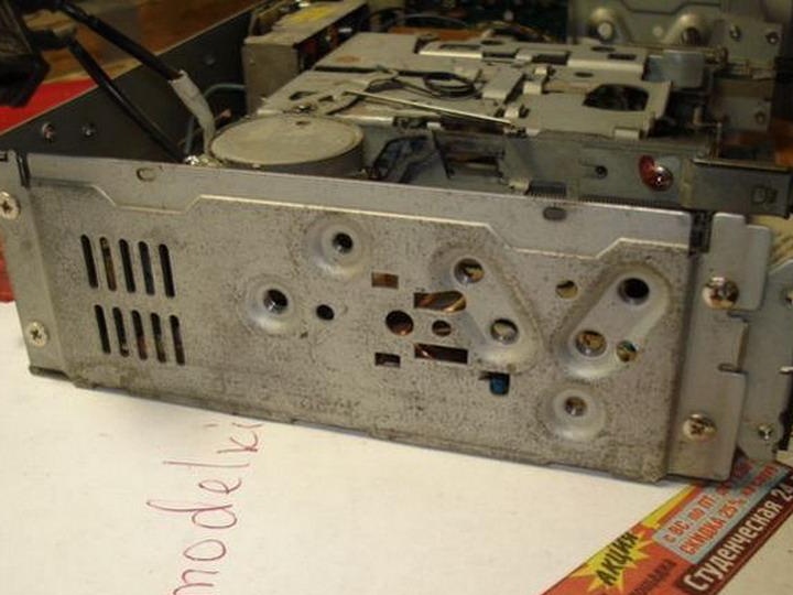
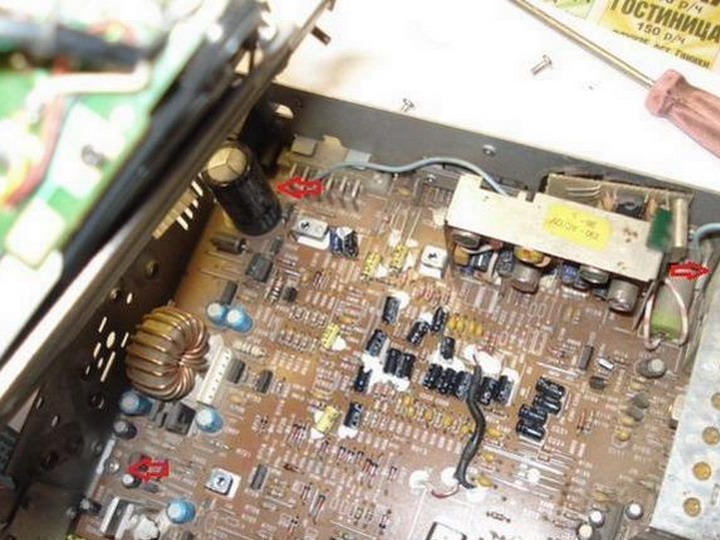
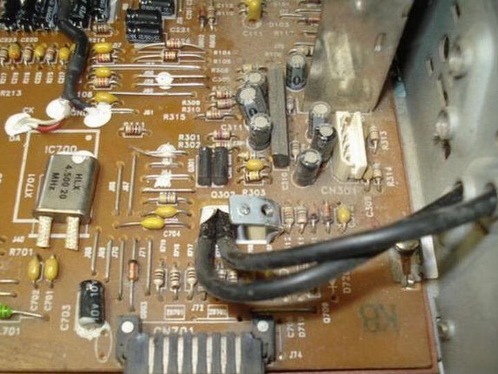
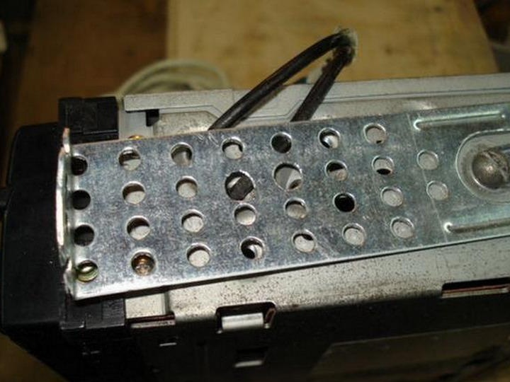
Unscrew all the radiator mounting bolts of the ULF chip, this is such a large aluminum part at the back of the radio.
Carefully remove it and put it aside. The arrow indicates the ULF chip; when reassembling, we will not forget to refresh the thermal grease on it.
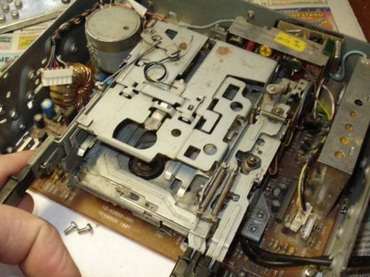
Unscrew the five cassette drive mounting bolts and disconnect the two connectors (variations are possible in another radio).
Disconnect the drive electronics connector.
Disconnect the magnetic head connector.
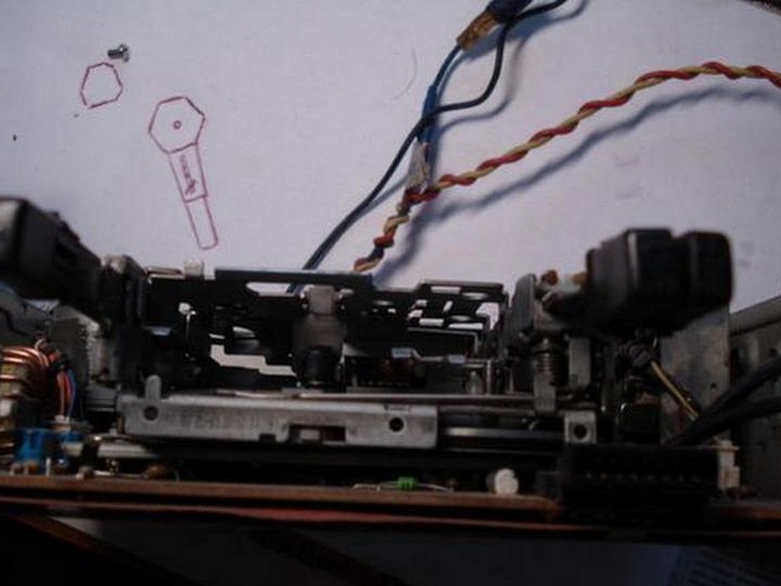
Now you can take out the drive itself and put it aside.
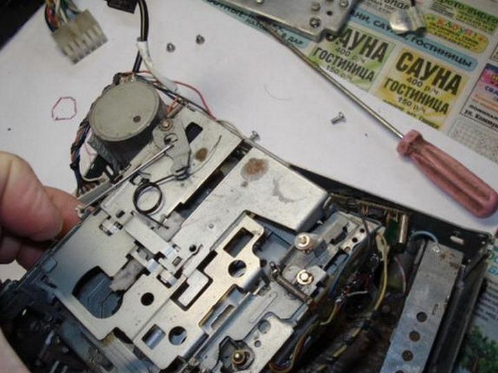
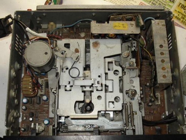
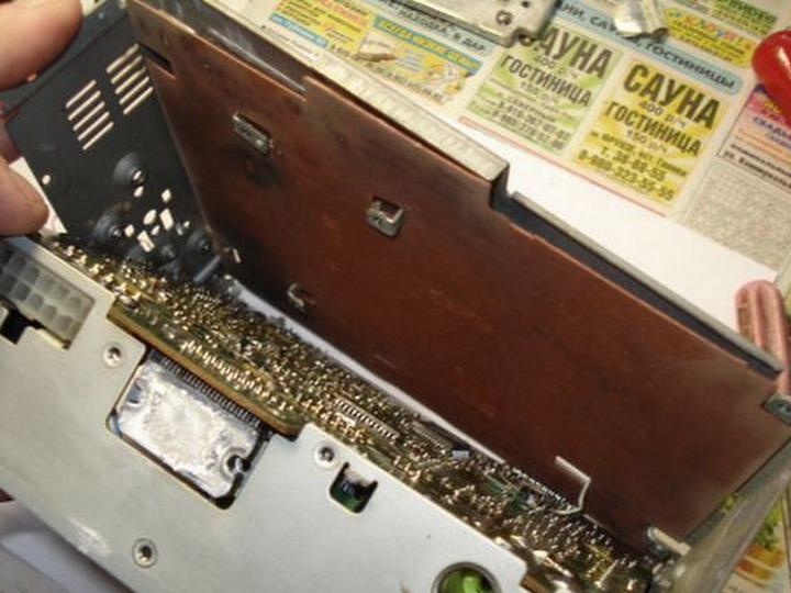
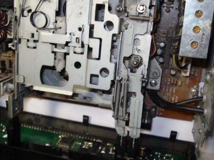
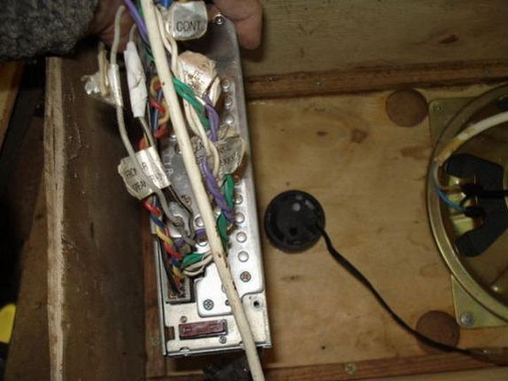
Before us is the main board, we twist four bolts in the corners.
You can remove the back cover of the case and begin to study the electronic circuit.
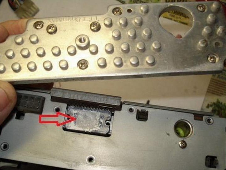
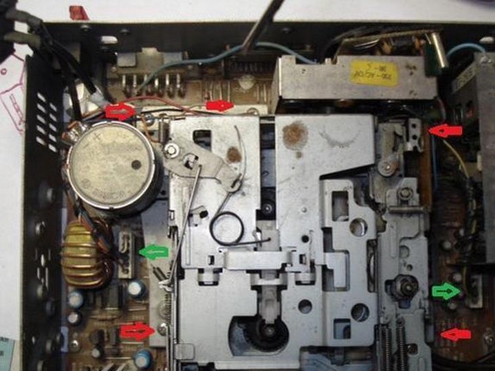
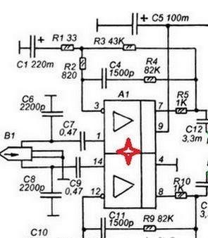
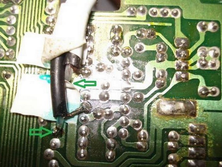
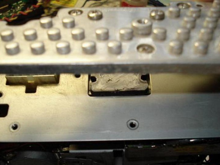
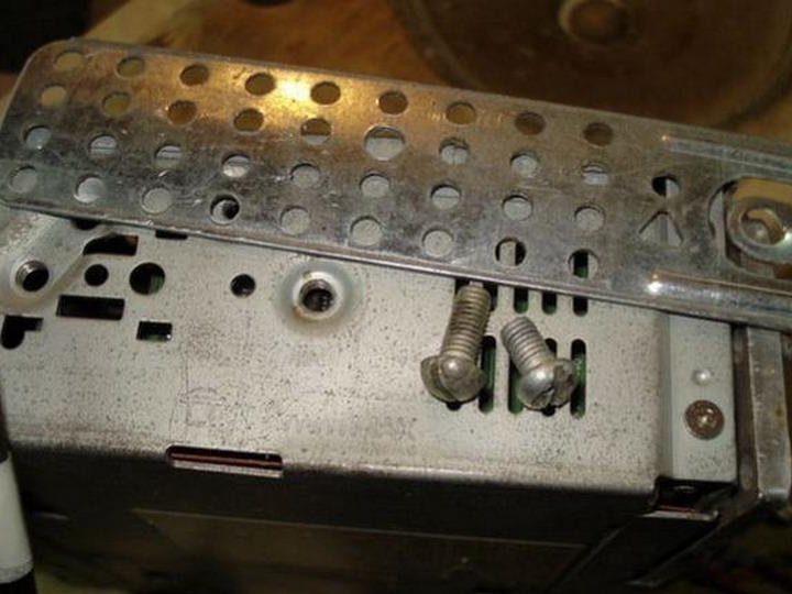
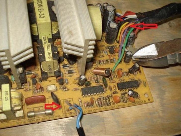
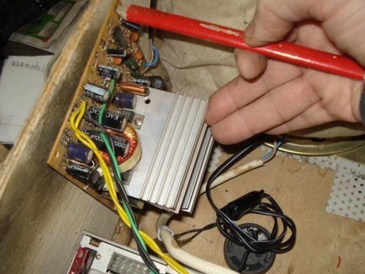
We are interested in a preamplifier, a microcircuit that stands next to the magnetic head connector.
On the picture: The pre-amplifier chip (red star), the magnetic head connector (green arrow), the resistors to which we will solder the audio cable (two green arrows).
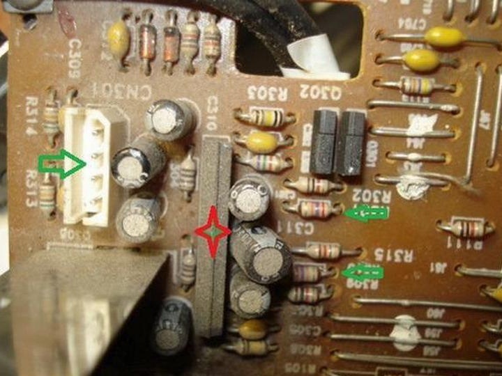
In a similar way, you will also find a chip in your radio.
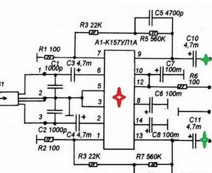
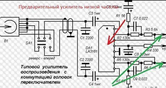
Variants of input amplifier circuits.
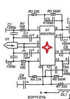
As you can see, all schemes are very similar and similar.
Let's assemble a simple audio cable circuit, solder two small electrolytes (but you can do without them) and a 3.5 mm mini jack.
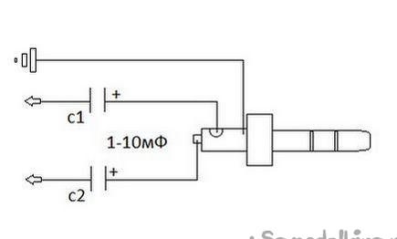
And this diagram explains where to solder the audio cable with a mini jack itself.
We solder the central conductors to the outputs from the left and right channel microcircuit, the screens to the common wire (case). Isolate, varnish the place of soldering.
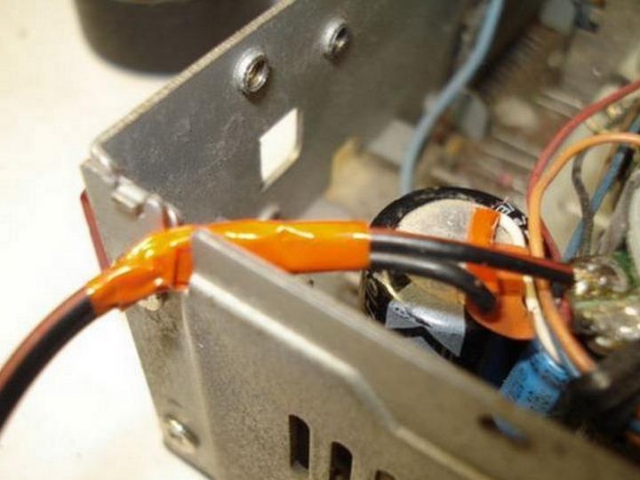
A convenient route leads the cable outside the radio.
We install the drive in place, tighten the bolts, connect the connectors.
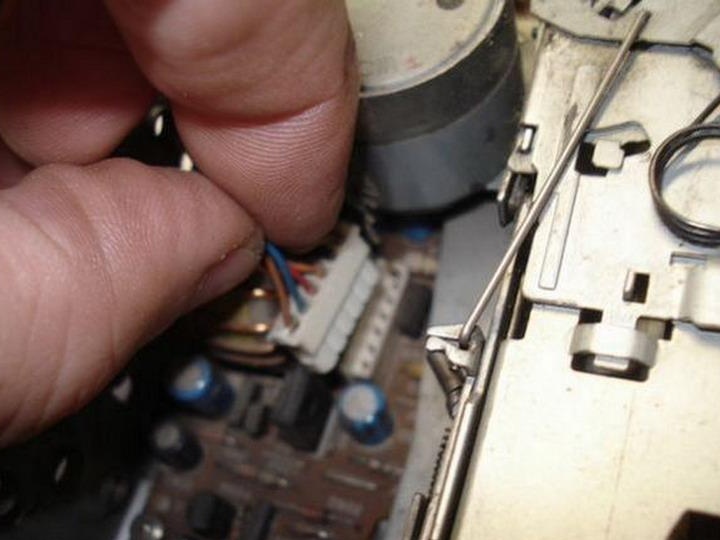
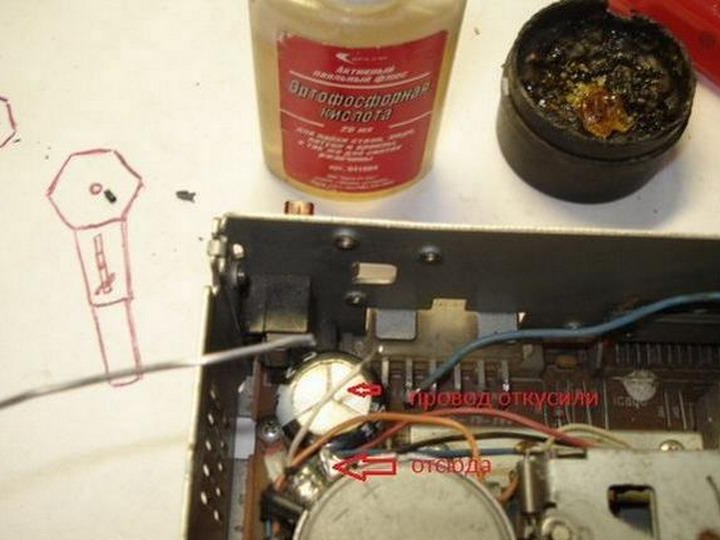
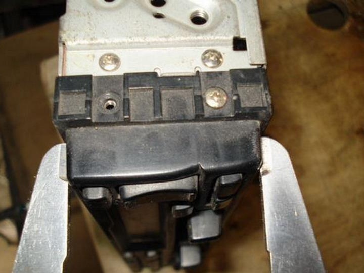
Now you need to make a switch to stop the cassette drive motor.
In order to send a sound signal through our cable that is outward to the output amplifier of the radio, you need to insert a cassette and turn on the playback mode, and so that it does not play along with our music from the phone, you just need to stop the motor. Of course, you can turn off the power of the pre-amplifier chip or other options, but this method is the simplest and most understandable for the unprepared.
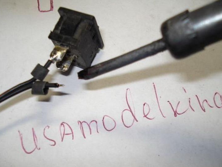
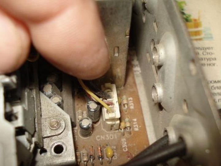
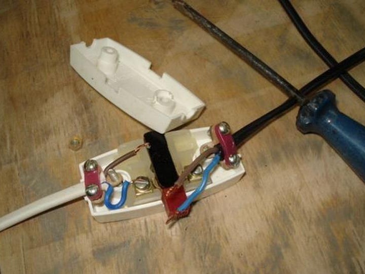
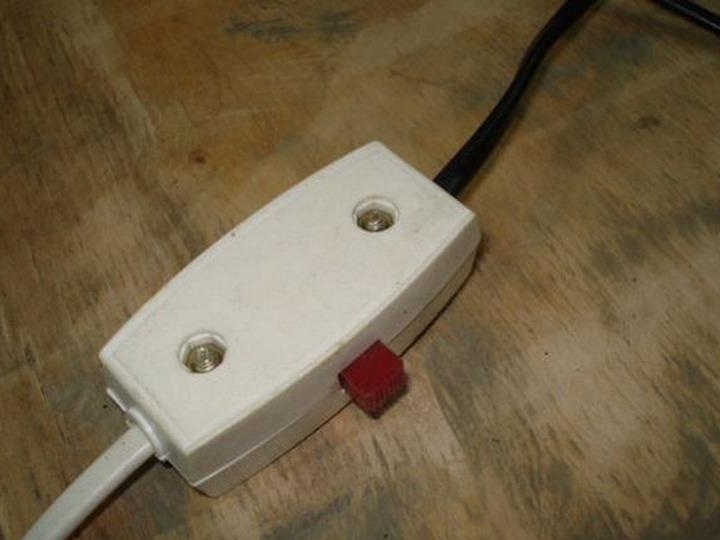
In the gap of one motor power wire, we connect our remote switch, it must be placed on the speaker housing.
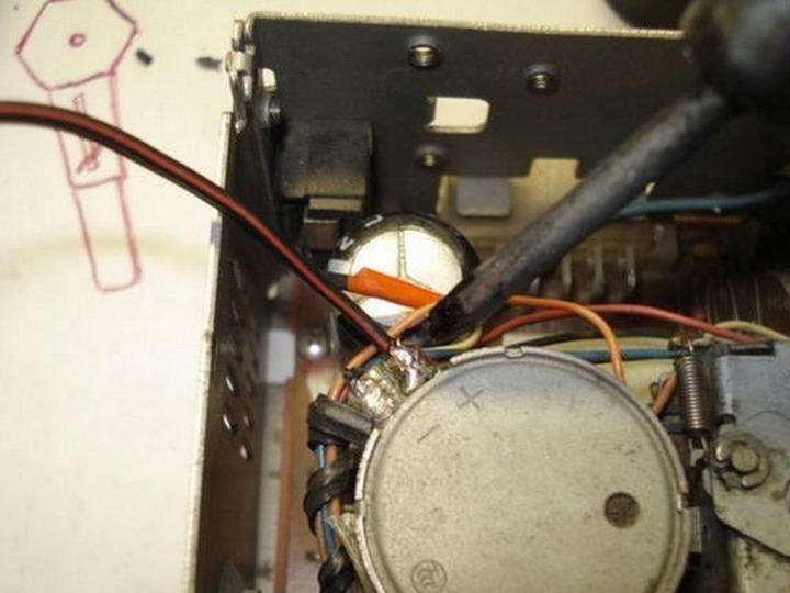
Isolate and remove it from the radio.
We continue the complete assembly of the case, we update the thermal grease.
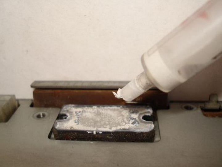
We fix the radiator in place.
Front panel
Everything is collected.
ITEM 3. Locksmith.
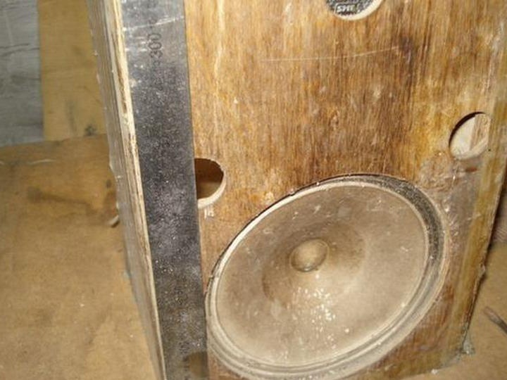
We clean and disassemble the column body.
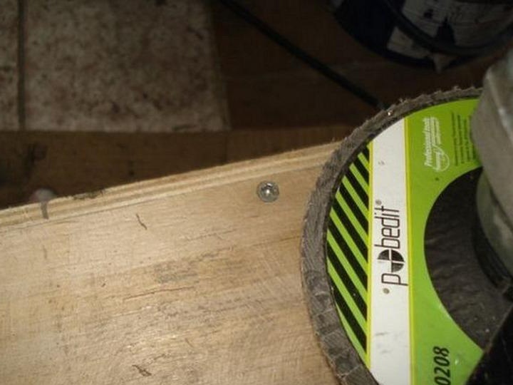
She doesn’t want to figure it out, we use the grinder.
Gone.
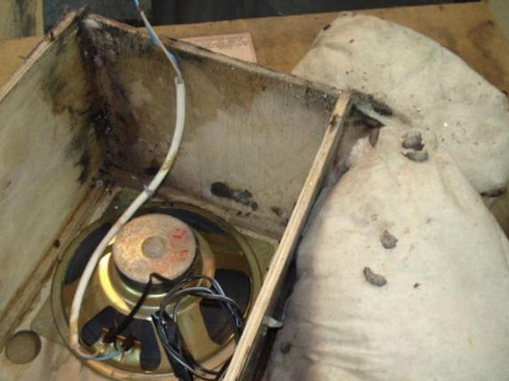
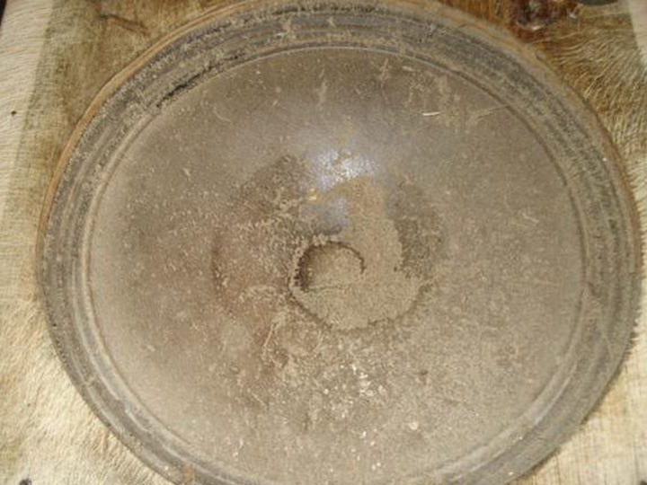
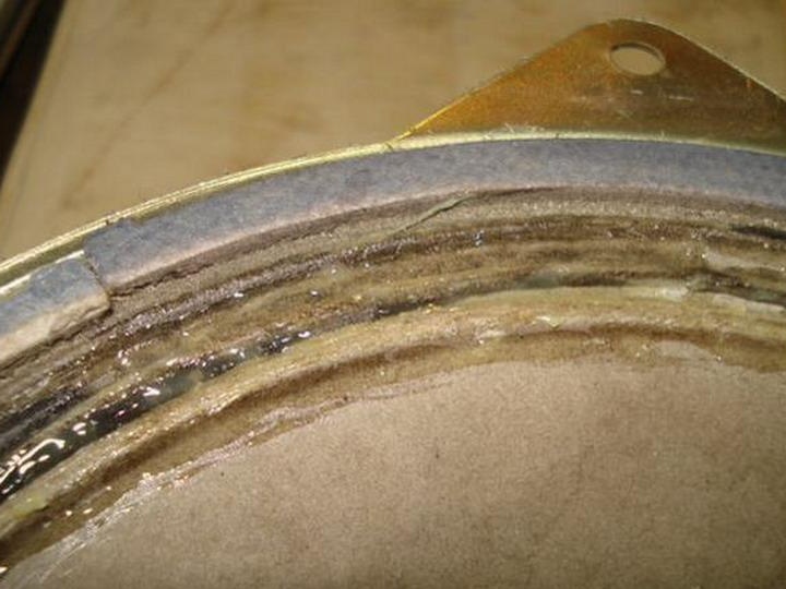
Let's see what's going on there.
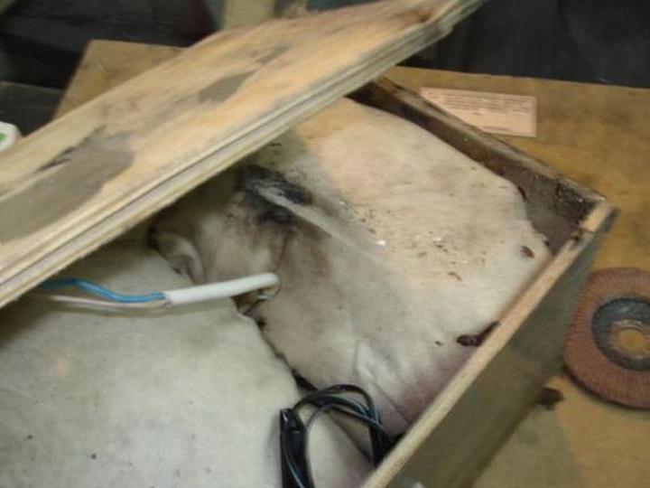
And what's going on, something terrible, from the remains of excrement, it became clear that there was a house of earthen toad!
But how is this possible!!! : no: The only small holes are at a height of 22 cm and never fell lower, and judging by the rest of life, the toad lived there for a long time and regularly walked outside. Here they are well-aimed jumpers. I can imagine how she was inside during a disco, a music fan damn it!
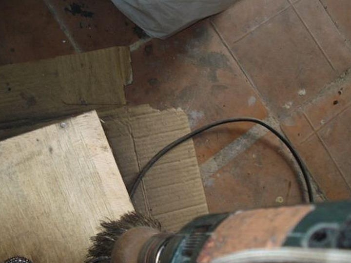
We process plywood with various tools.
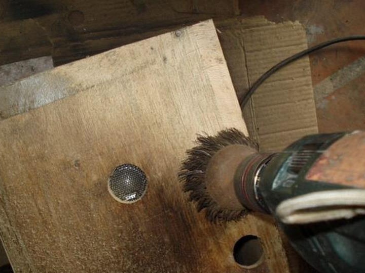
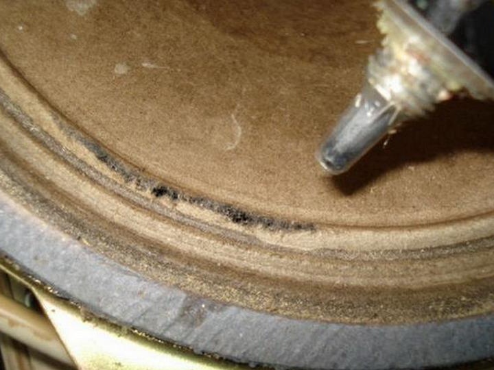
Caution !, I hooked on the old diffuser paper.
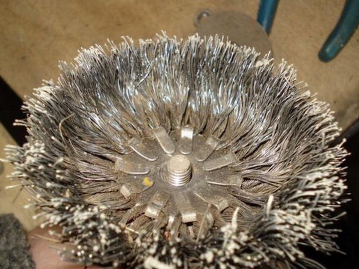
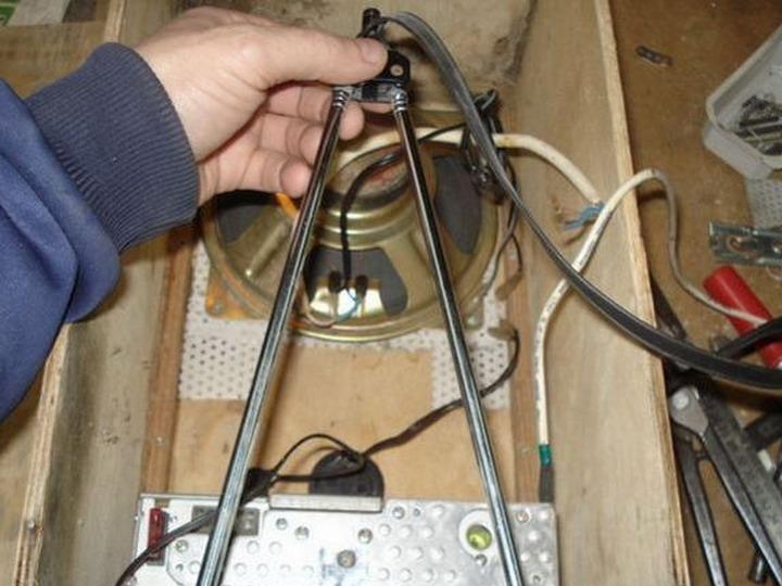
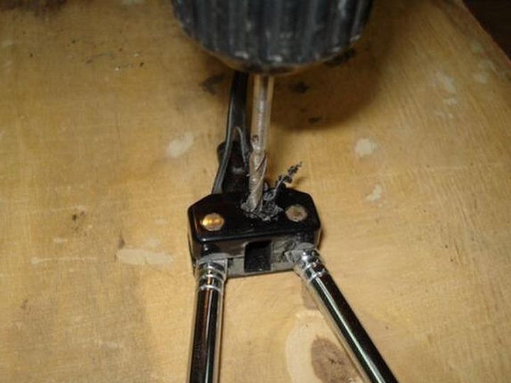
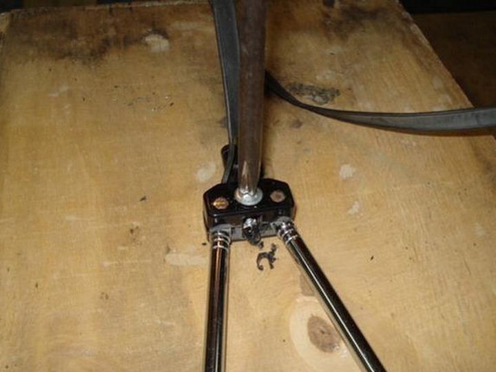
During the reverse, the brush nut was untwisted, I found out how it is arranged inside, see also who did not see it.
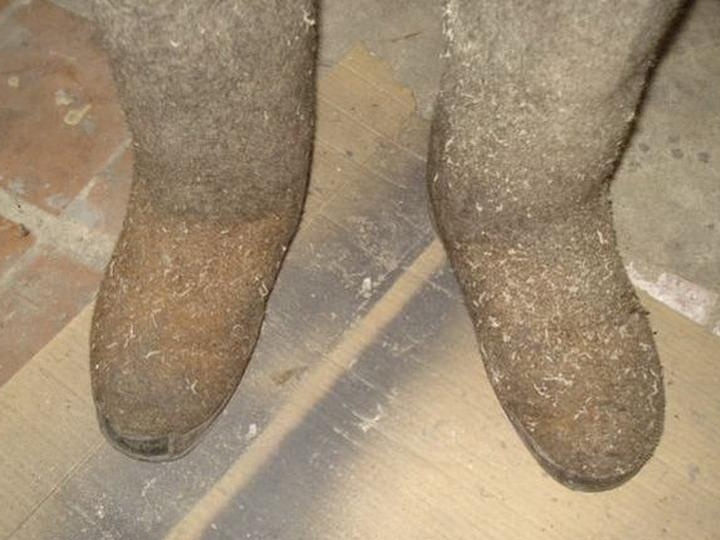
The best shoes when working with such a brush, flying needles do not see your feet!
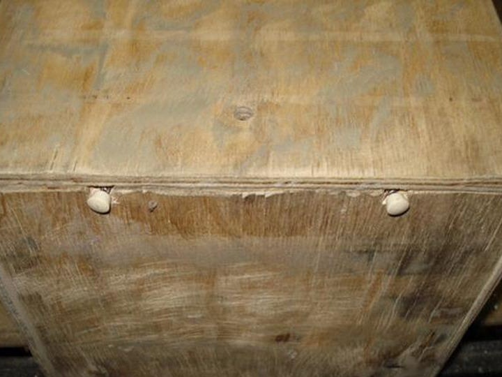
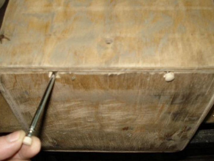
Stitching the hats of screws.
Finished rough cleaning of the housing.
ITEM 4. Installation of the insides.
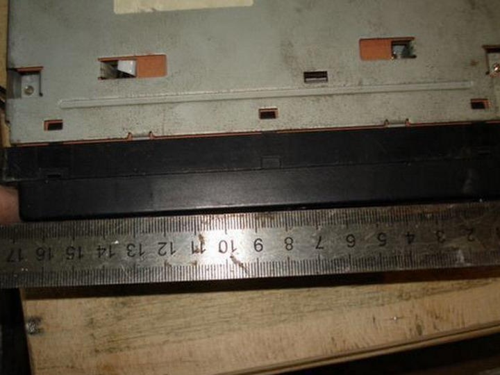
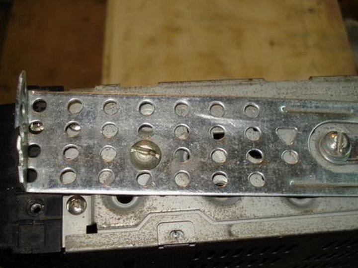
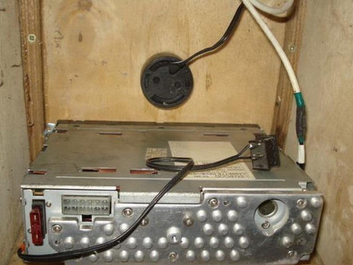
Try on how the radio is placed inside.
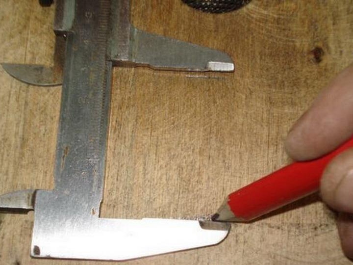
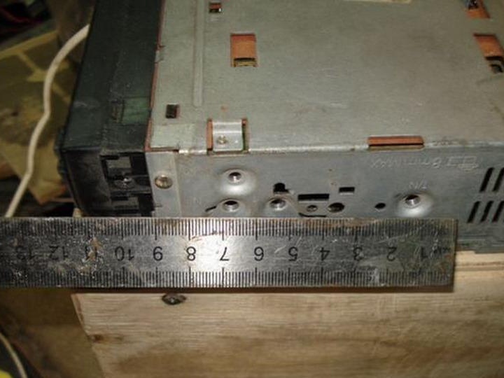
We measure the landing size of the front panel, it is necessary that only it passes outside the plywood of the case.
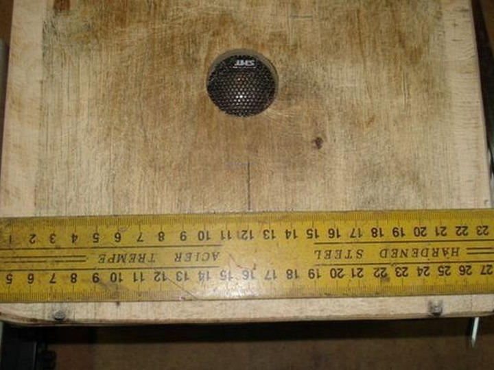
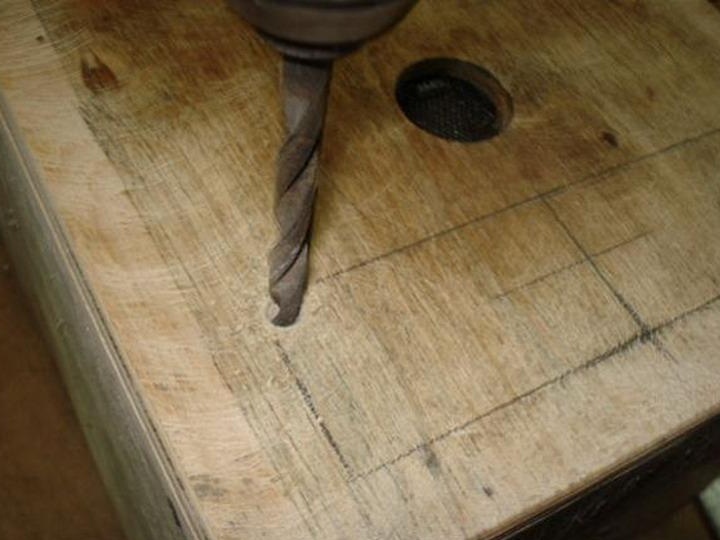
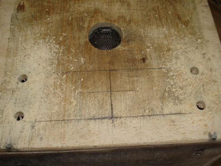
We make markup in size.
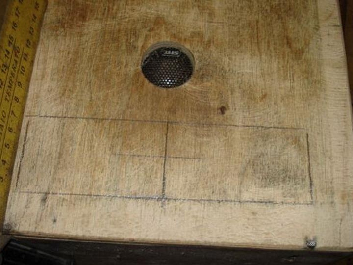
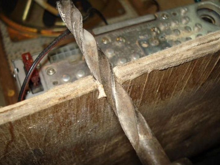
Drill a drill at 8 in the corners of the hole.
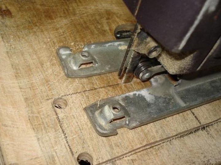
Saw a rectangle with a jigsaw.
We try on how the panel fits, if necessary, customize more.
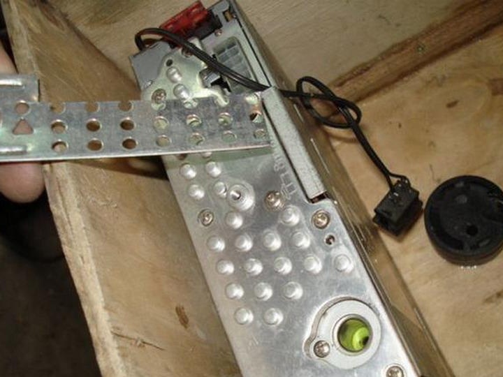
We make measurements for the manufacture of fasteners.
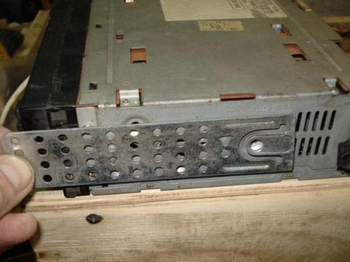
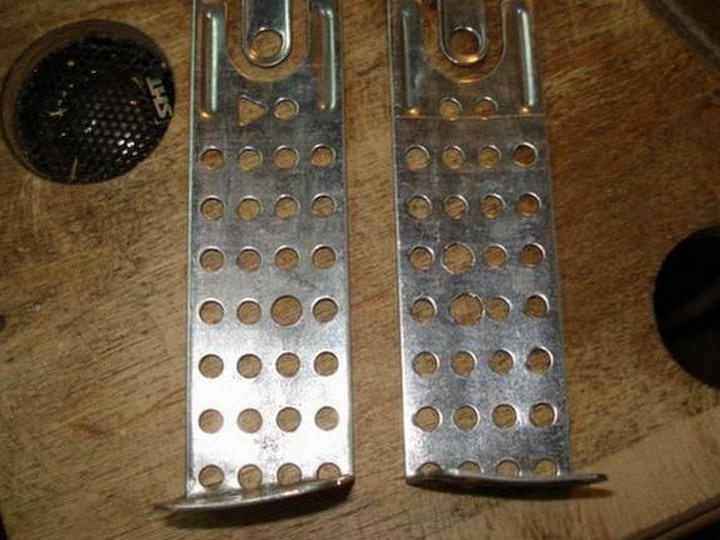
Very convenient pieces of iron these suspensions came in handy this time.
And the holes fit perfectly.
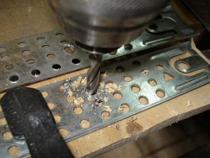
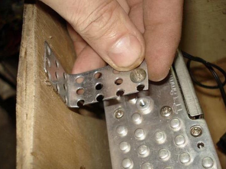
Drill a drill 5 mm.
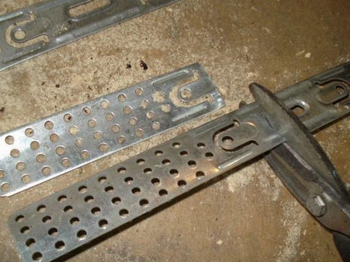
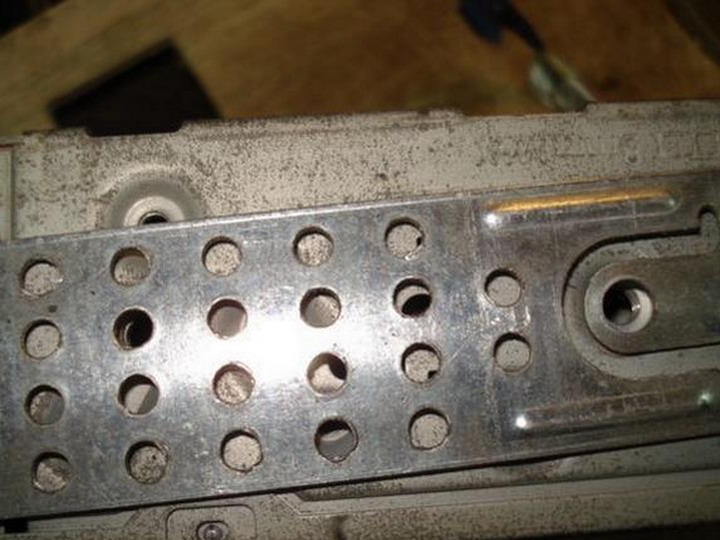
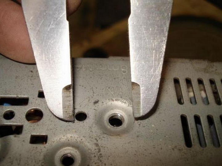
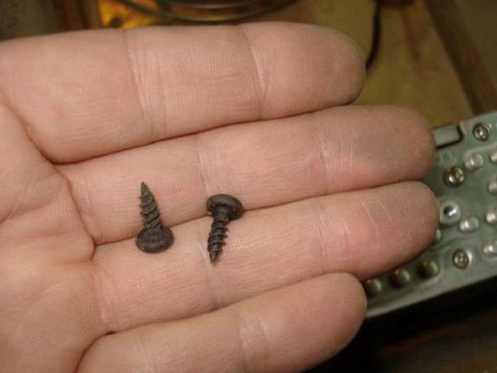
We select the bolts, as written on the case, the length should not exceed 8 mm.
We personally check the safe depth.
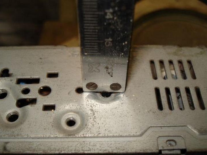
They deceived, the deepest thread turned out to be 15 mm., And the rest are generally bottomless, it turns out, except for the first one, you can screw a bolt of almost any length into the rest and not soar with sawing.
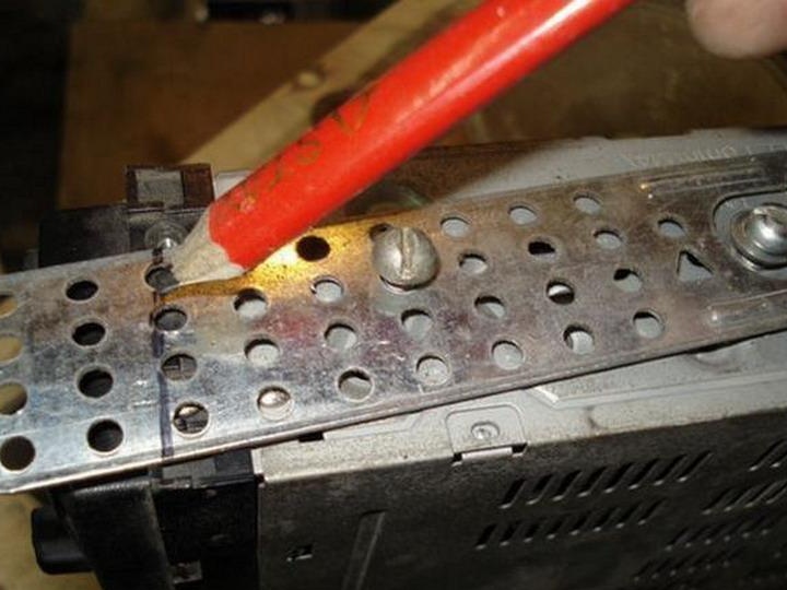
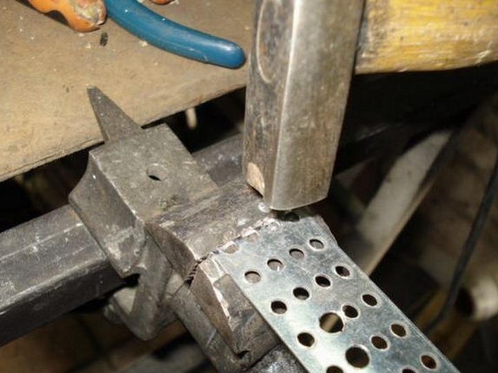
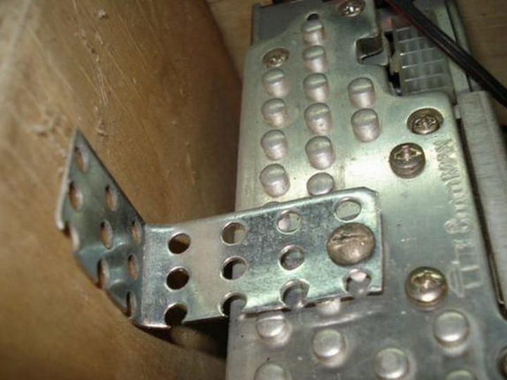
We bait the bolts and outline the bend line of the attachment angle.
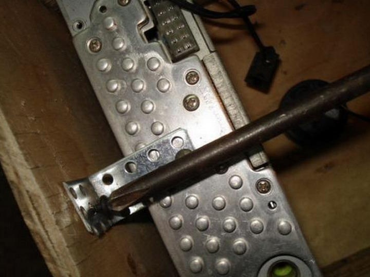
Clamp tightly in a vice.
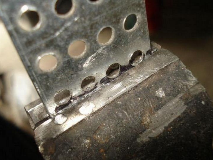
And hammering, bending the corner.
In a similar way we make fastening for the other side.
Screw both into place.
Install everything inside the case.
Need small screws.
A screwdriver is required long, otherwise nothing.
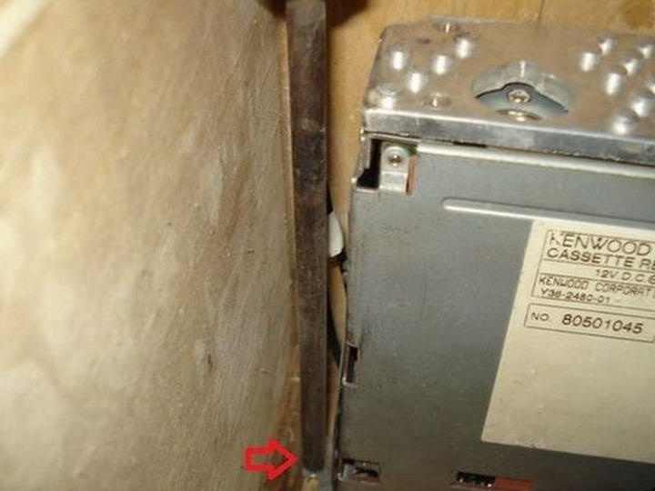
A third mounting point is also required.
Now it definitely will not fall off from constant vibrations.
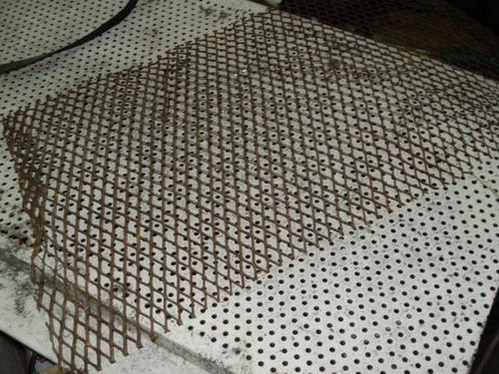
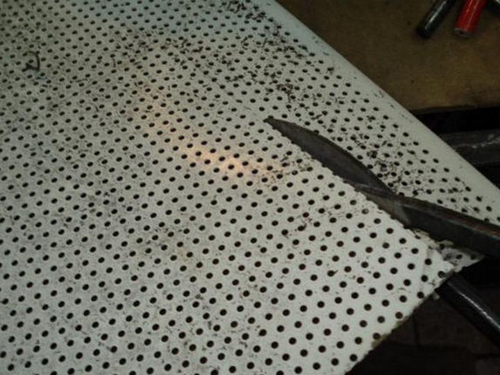
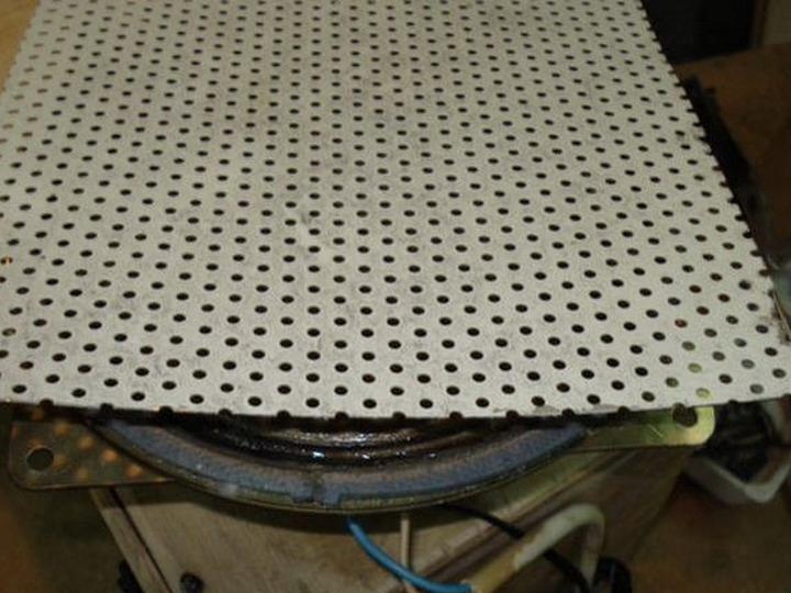
Take a suitable grill or mesh, make protection for the speaker.
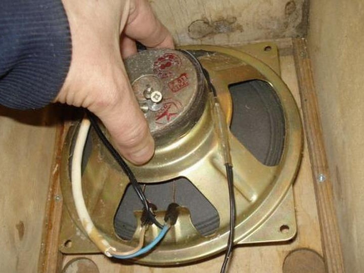
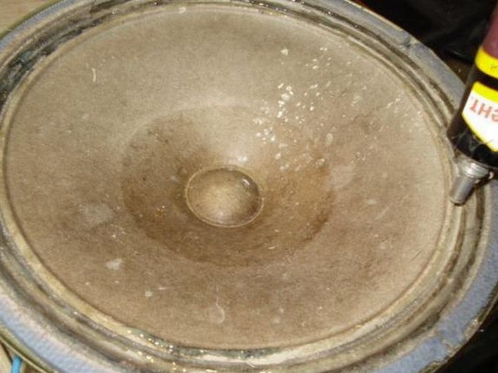
Unscrew the screws and take out the speaker.
It's time to treat the old speaker.
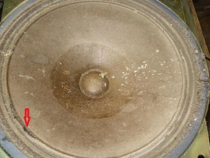
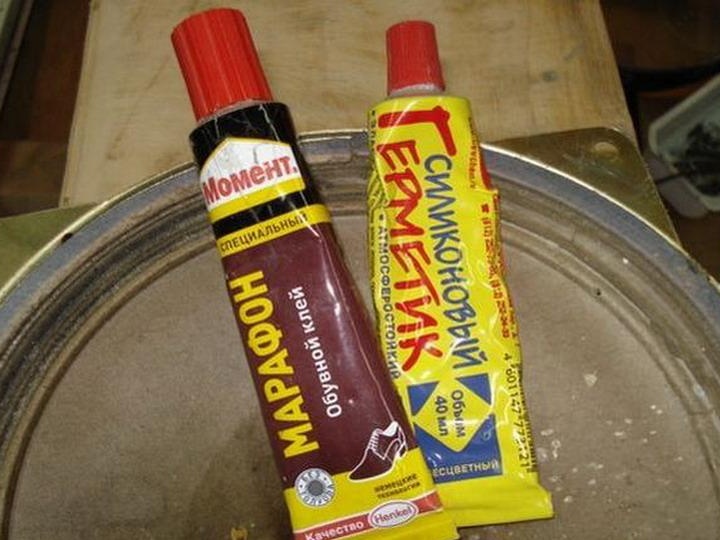
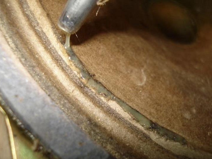
Apply elastic silicone sealant or rubber glue.
Put on a gust.
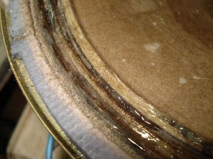
And also around the circle.
While the glue dries, cut the grate to size.
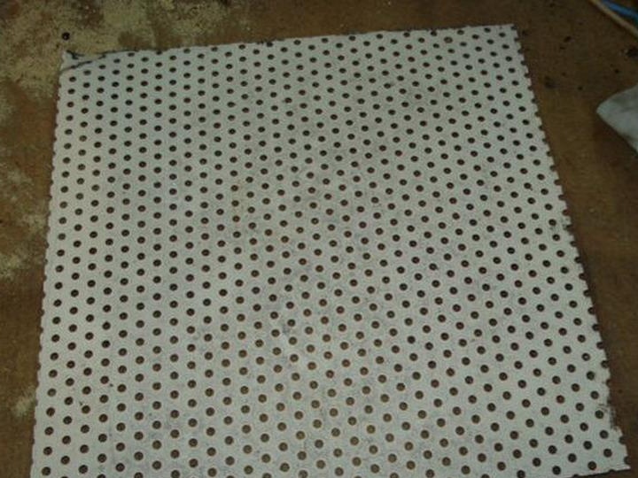
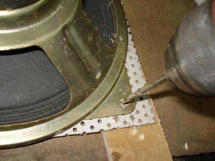
Drill holes for screws.
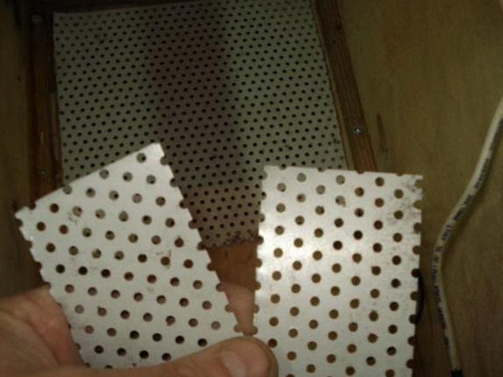
For one, we close the holes of the bass reflex so that the sparrow settles in.
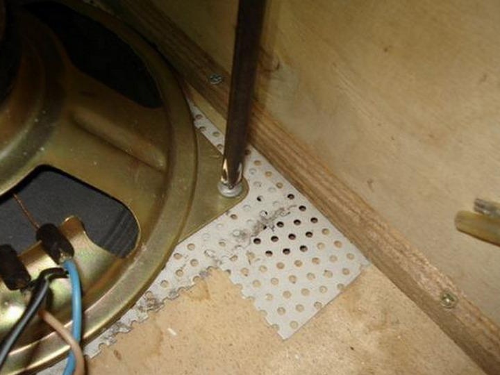
Screw the screws into place.
The first glance is what happens there.
It's time to tackle the antenna, I found one from the TV.
Let's drill a hole for fastening.
Screw on the screw with a wide hat.
We mark the places where the antennas exit.
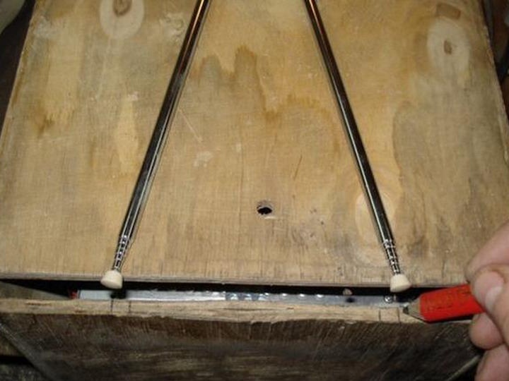
We make cuts with a jigsaw.
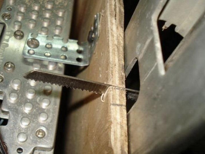
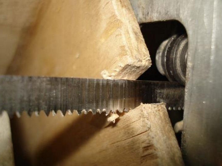
You can mill a bit with a drill.
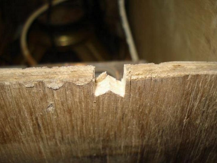
Check how everything went.
We remove the antenna connector with a matching transformer.
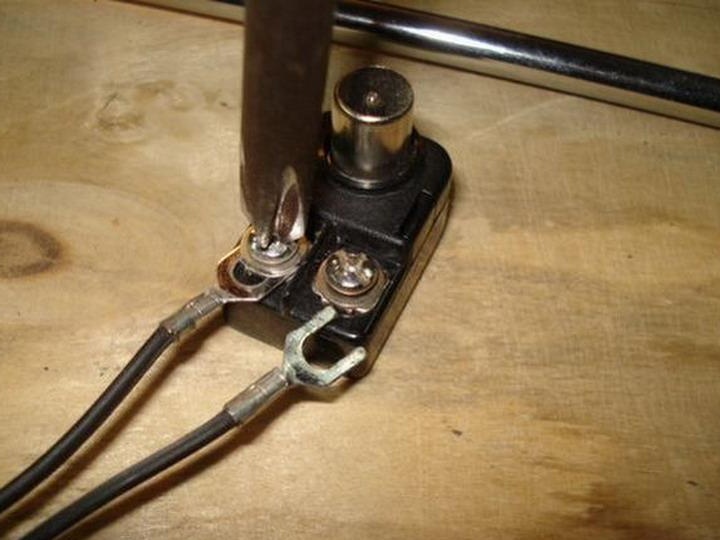
A suitable bolt or nail is crimped with contacts.
Isolate.
We check how it came in.
We put sound insulation in the unnecessary half of the body.
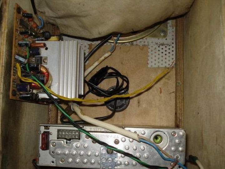
ITEM 5. Wiring.
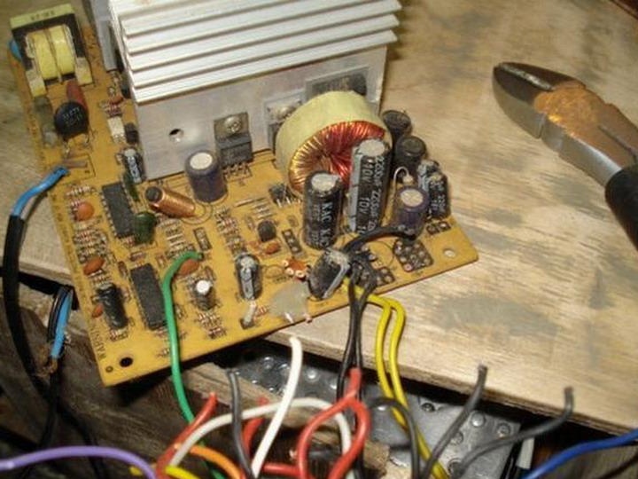
We get only the board itself from the PSU case.
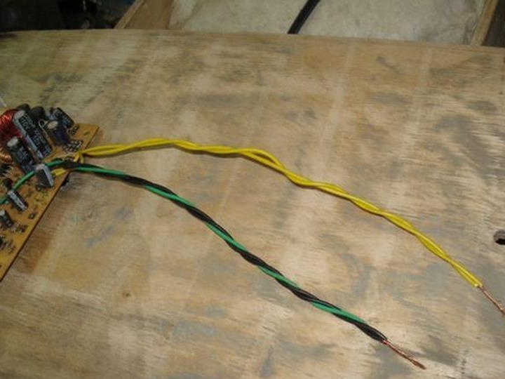
By biting out all the extra wire, leave only yellow + 12 in., Black and green (for ATX).
Solder the 220 volt power wire in place.
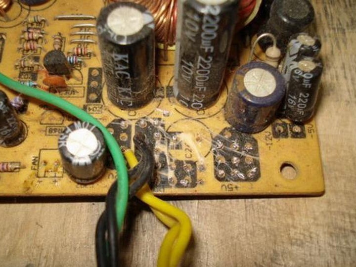
Connect the green and black wires.
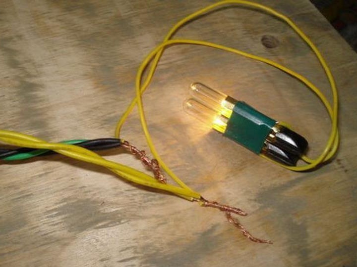
Check the operation of the power supply using 12-24 century. light bulbs. All is well, continue on.
We outline the mounting points of the board in the case.
We use short self-tapping screws and small cambric or tube linings so as not to break the board.
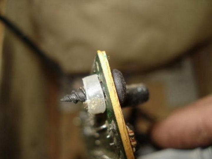
Install, fasten.
We insert the radio connector into place.
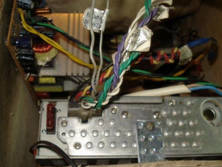
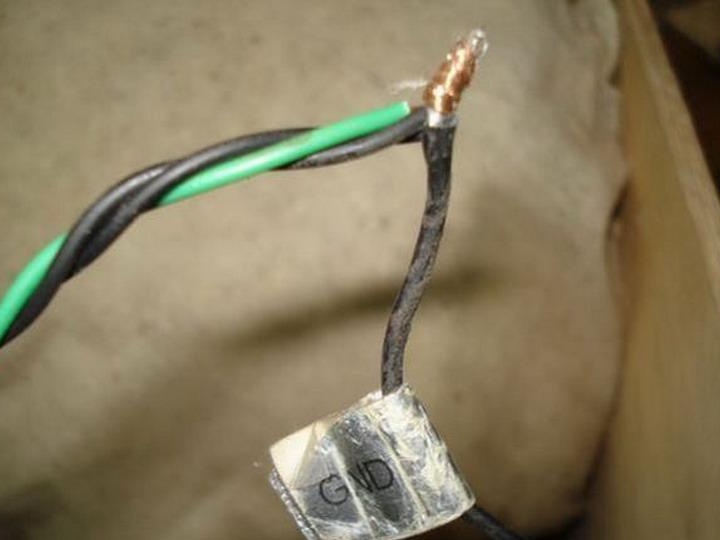
We connect the power wires to the radio, black-green with the GND radio.
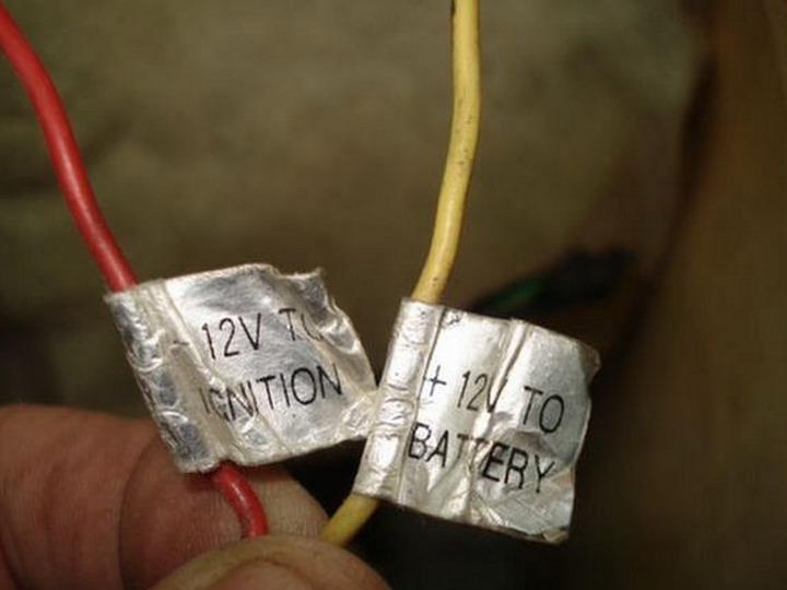
We find such wires and connect them together to the +12 V yellow wire. BP
We connect the speaker to any of the channel pairs.
If there is no + and - marking on the speaker, you need to find them yourself using a conventional battery, briefly attach it to the speaker coil outputs and observe that the diffuser is pushed out rather than retracted. The correct direction of ejection correspond to + to + batteries. We attach everything correctly in accordance with the experiment.
We isolate and fasten everything so that nothing is stuck.
We bring the engine switch to the housing.
On the power wire we make a knot, as a limiter for pulling out.
We separate the PSU radiator with cardboard so that it does not crawl or cover the cotton.
Check that everything is connected.
Close the case.
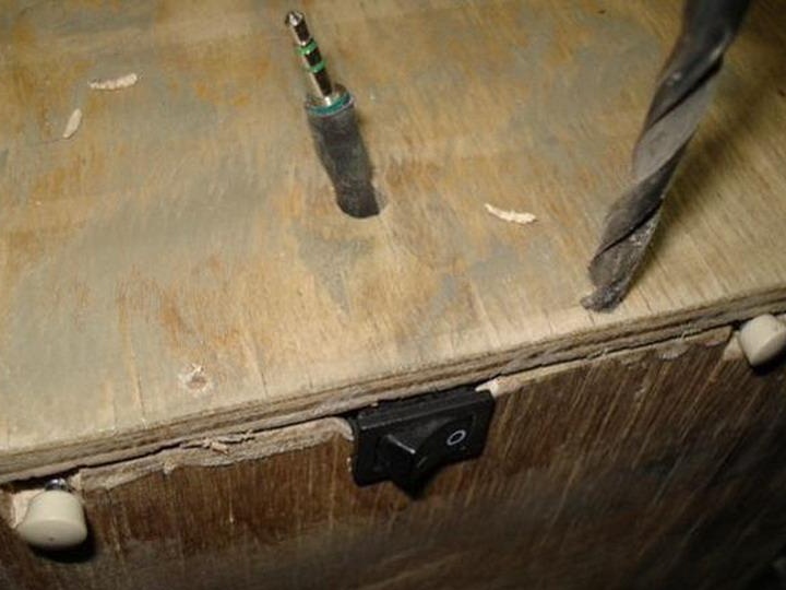
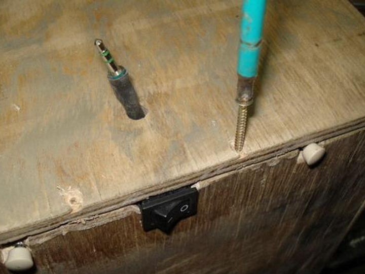
We put the switch in the section of the supply wire.
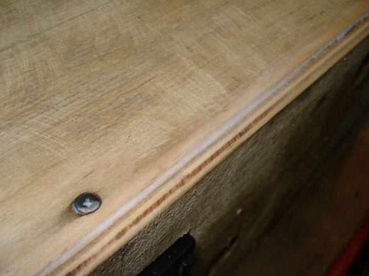
We drill holes for self-tapping screws, make holes for hats.
We twist a pair of fasteners and turn on to check how everything works.
If everything is fine, then we twist everything thoroughly using glue for cracks.
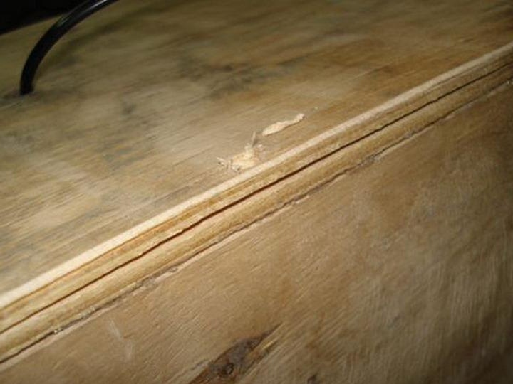
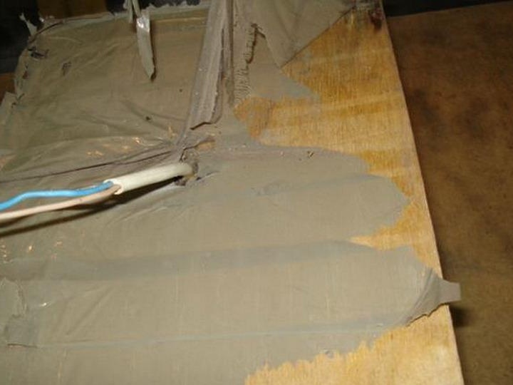
We coat all defects and cracks.
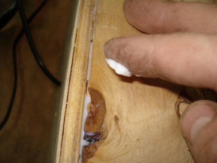
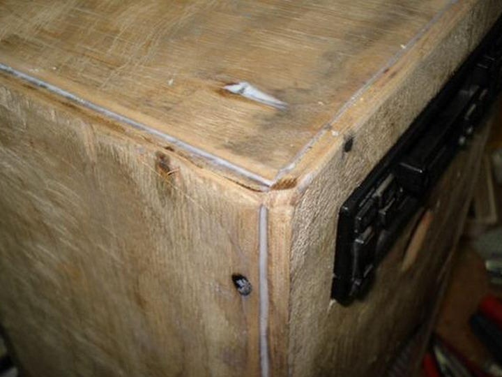
Leave everything to dry completely.
Further refinement of the case will be done in the next part.