Incubator was made to incubate home birds such as quail, chickens, ducks, geese, turkeys. Such a variety was made possible thanks to microcontroller automation.
Materials for the case:
- a sheet of chipboard or old furniture panels (like mine)
- floor laminate board
- aluminum sheet with perforation
- two furniture canopies
- self-tapping screws
Instruments:
- A circular saw
- Drill, drill, furniture drill (for awnings)
- screwdriver
Materials for automation:
- circuit board, soldering iron, radio components
- transformer for 220-> 12V
- electric drive DAN2N
- two 40W incandescent lamps
- 12v computer fan, medium size
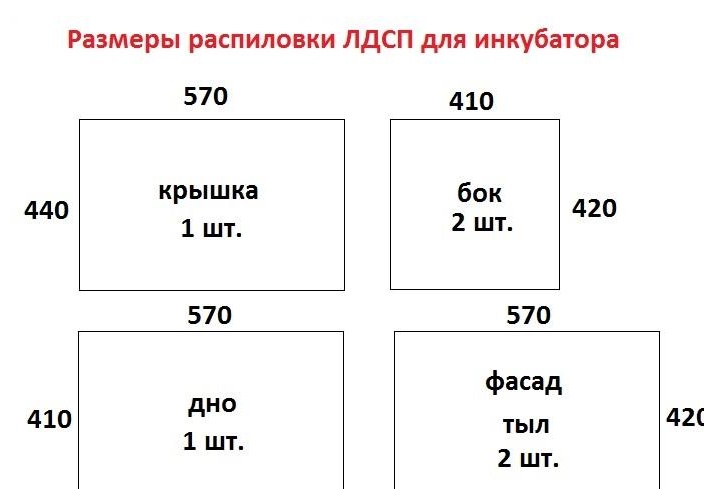
Item 1. Production of the case.
Using a circular saw, we cut the workpieces from the chipboard sheet in accordance with the dimensions in Fig. 1.
In the resulting blanks, in accordance with Fig. 2, drill holes D = 4 mm. for self-tapping screws, they are marked with red circles, green circles indicate the place of attachment of the roof canopies. Assembly of the body is carried out in accordance with the scheme. We install a cover on two furniture hinges.
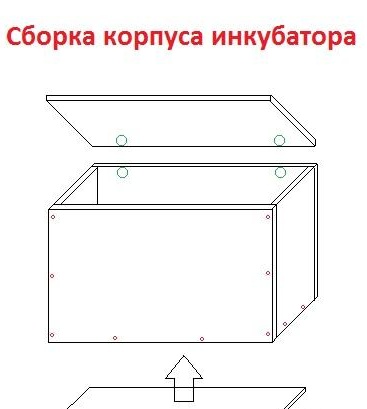
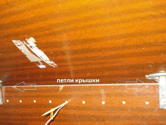
We drill rows of ventilation holes D = 5 mm. front and rear, top and bottom of the case.
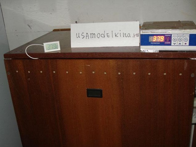
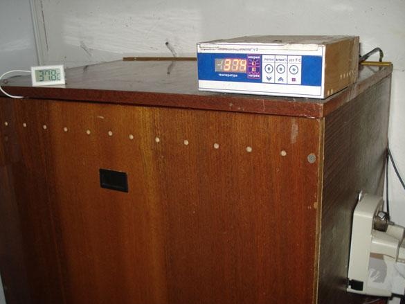
As a result, a completely finished case for the incubator was obtained, it is not necessary to additionally insulate it, electronics perfectly copes with heating the drawer with just two bulbs.
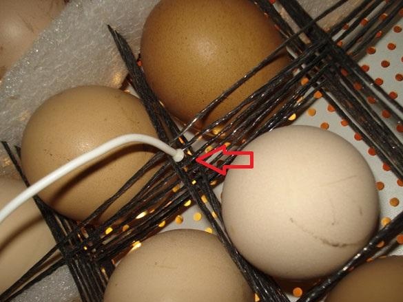
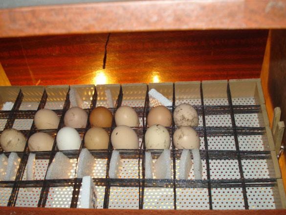
Item 2. Tray for eggs.
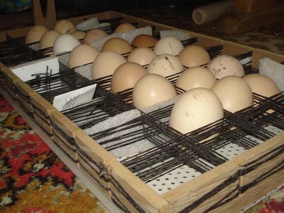
The main part of the tray is the base, an aluminum sheet with frequent openings for unhindered circulation of heated air. If there is no similar material, then you can make the bottom of any sheet material of sufficient rigidity and drill a lot of holes D = 10 mm in it.
I made the sides of the laminate, in which cuts are made up to the middle with a pitch of 50 mm, the net for holding the eggs is braided in them from garden twine, and at the end of the twine, the cuts are glued with titanium glue. It turns out a cell of 50x50 mm, the size of large duck eggs, so as not to make many different trays for different birds, so chicken eggs in some places have to be slightly burst with foam bars. The capacity of such a tray is 50 eggs. Goose eggs are laid in a checkerboard pattern, a net of twine compresses the bookmark well.
For quails, a separate tray similar to this is made, but with a step of a cell of 30x30 mm, the capacity of which is 150 eggs.
The incubator capacity does not end there, because there is a second tier, a second tray which, if necessary, is installed on top of the first tray.
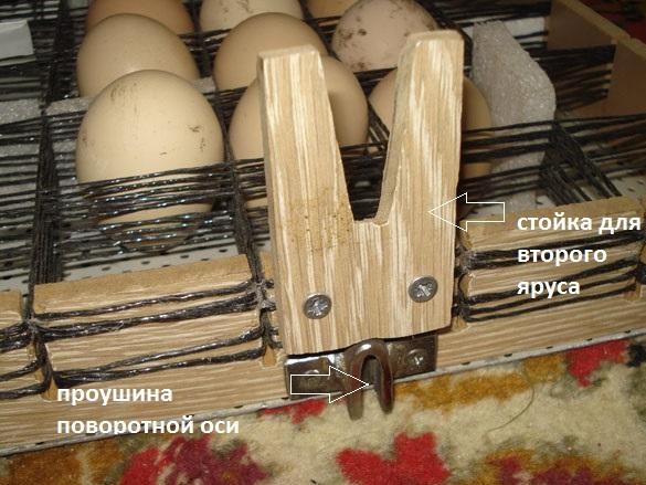
This (V) shaped mount is located at both ends of the tray and is only needed if a second tray is planned. At the upper additional tray, the same mount is only directed downward and enters the dovetail in the lower tray with a wedge.
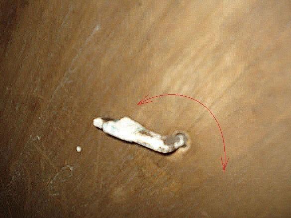
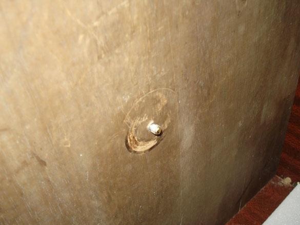
Also visible in the photo is a metal eye for attaching the tray to the flag of the rotary mechanism.
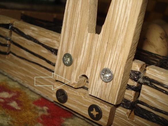
Here you can see (V) the mount and the hole of the support axis of the tray.
Item 3. Device for tilting the egg tray.
To turn the axis with the flag, which in turn tilts the egg tray 45 degrees to one side and the other, I used the DAN2N electric drive, which is used for ventilation pipes.
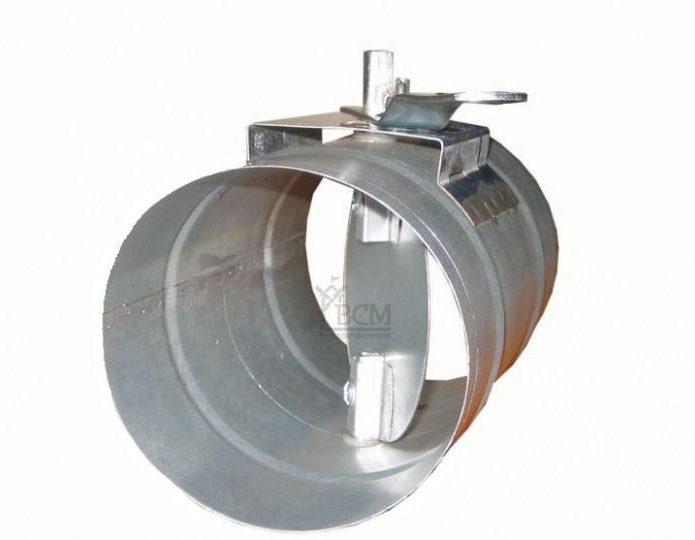
It is perfect for this job.
This drive works out a slow rotation of the axis 90 degrees from one extreme point to another, and when it abuts against the limiter of the rotation angle, then, when the current in the motor is exceeded, it switches to stop mode until the control contact changes its state to the opposite.
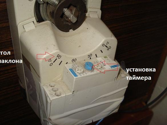
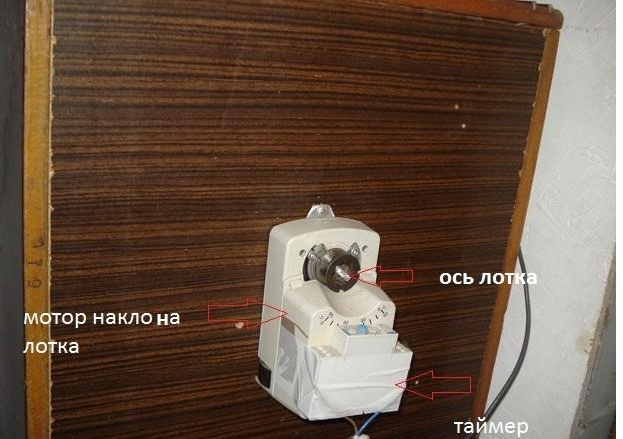
To control the change of position on the control contact, any timer that will close and open the contact after a specified period of time is suitable. For this purpose, I found a French timer with adjustment from a split second to several days. But all these functions are already in our microcontroller control unit, therefore, to turn the tray, we just need to use any small motor with a gearbox, and the control unit will take charge of it.
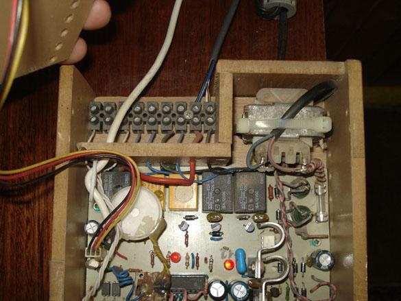
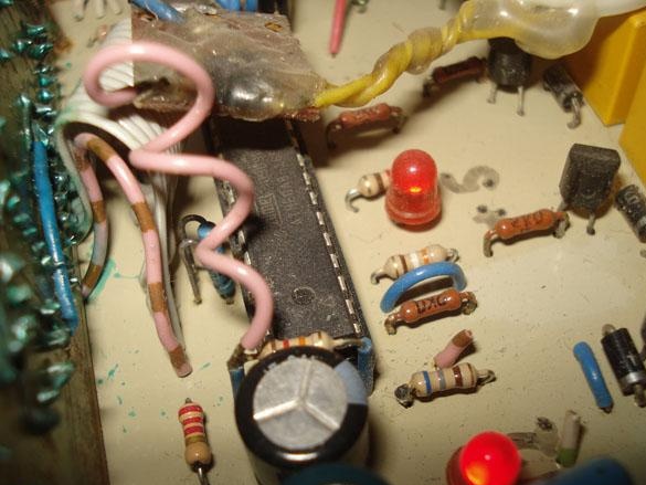
Item 4. The control unit.
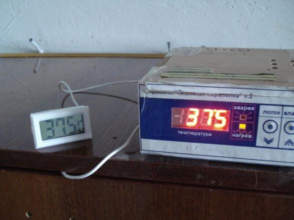
The control unit or heart of the incubator, which determines whether you will get chickens or not.
With the publication of the popular Atmel microcontroller, many interesting projects began to appear, including simple and very reliable thermostats. So, the March project from the 2010 Radio magazine turned into a full-fledged complete incubator control module with all possible functionality. And this: the adjustment range 35.0С - 44.5С., Indication and alarm in case of emergency, temperature control by a complex algorithm with the effect of self-learning, automatic tray rotation, humidity control.
When heating PETN (in our case, incandescent lamps), the algorithm selects the heating power, so that the temperature goes into balance and can be constant with an accuracy of 0.1 g.
The emergency mode will help out if the output triacs are damaged, the control passes to the analog relay and will maintain the temperature in the permissible range until the breakdown is fixed.
To control the rotation of the trays, the controller provides a range of adjustments up to ten hours, supports the presence of tilt limit switches, and without them, by setting the time to turn on the motor to travel the desired distance.
Automatic humidity control is controlled by a second electronic wet thermometer, a psychrometric method of calculation and when necessary, the load will turn on - a sprayer or an ultrasonic fog generator with a fan.
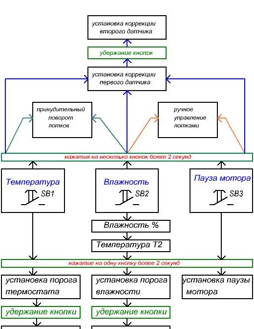
All manipulations of adjustments are made by three buttons.
The circuit uses temperature sensors DS18B20, the accuracy of which with an accuracy of 0.1 degrees can be set from the control unit menu.
Scheme of the incubator control unit on the Atmega 8 MK.
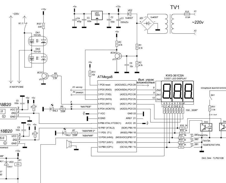
Depending on the used output power keys, you can apply different options for output circuits with different connection points and firmware options.
* If pulse transformers MIT-4, 12 with a connection point (A) are used to control thyristors / triacs, then this circuit is used.
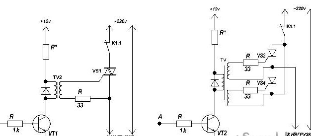
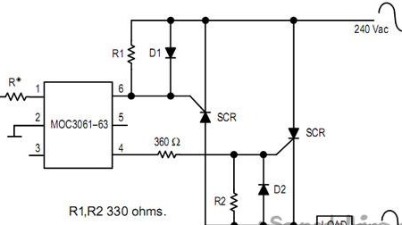
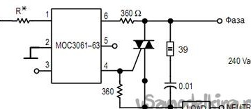
* Management of optocouplers of MOS.
Firmware - Phase-pulse, connection at point (A), MOC3021, MOC3022, MOC3023 are applied (without Zero-Cross)
Firmware - Low-frequency PWM, connection at point (V), MOC3041, MOC3042, MOC3043, MOC3061, MOC3062, MOC3063 (with Zero-Cross)
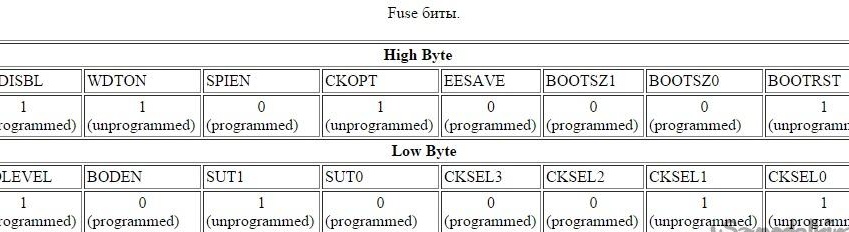
For firmware: MK works from an internal 4 MHz generator RC.
Download firmware here
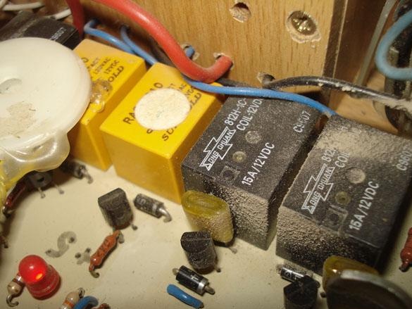
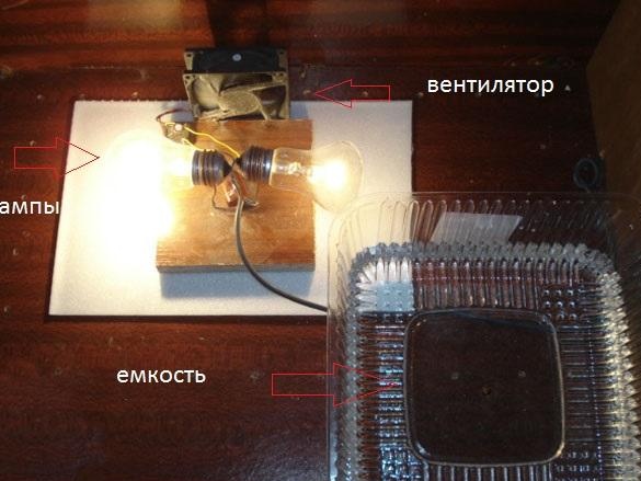
Point 6. Heater and fan of air circulation.
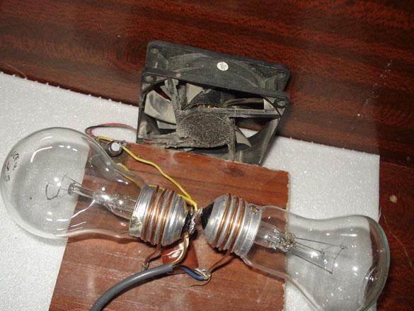
Two 40 W incandescent lamps are connected to the output of the power switches. each, further parallel to the lamps, a fan power circuit is connected, which starts to rotate with the lamps on.
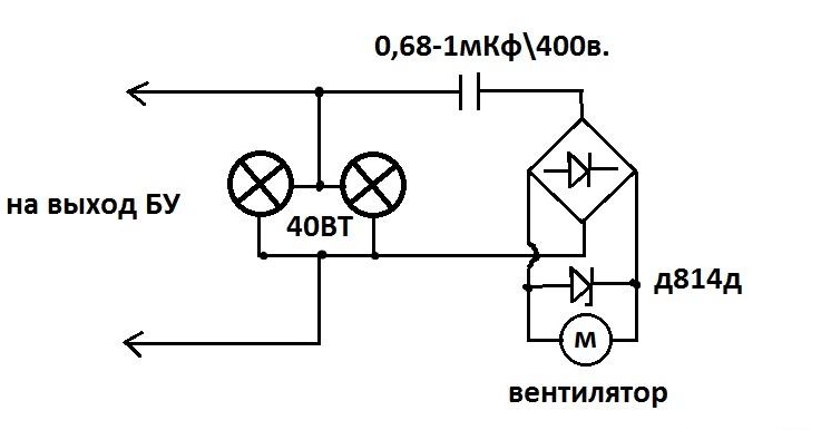
A container of water is placed next to it to maintain the necessary humidity.
For the initial calibration, you need to use several thermometers and set the error of the sensors through the menu.