

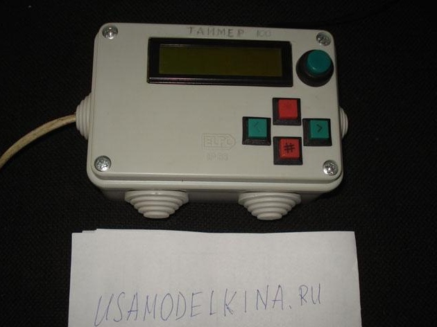
I want to offer the masters for consideration and possible repetition, a very simple scheme, a very good timer. With convenient menu navigation, with a liquid crystal LCD display, with a real-time clock, with the smallest possible number of parts, and with all this, you can program as many as one hundred time intervals during the day.
Compact size
Timer Check Video
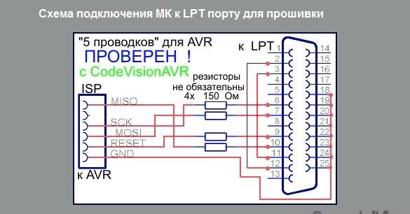
The heart of this timer is the very popular and no longer expensive Atmega8 microcontroller. You can say that for the firmware we need a programmer which is not, but this is not so, for Atmega firmware it’s enough just five short 10-15 cm. Of wires connected through 150-200 Ohm resistors. directly to the LPT port according to this scheme.
For this reason, these microcontrollers have become the most popular with ham enthusiasts.
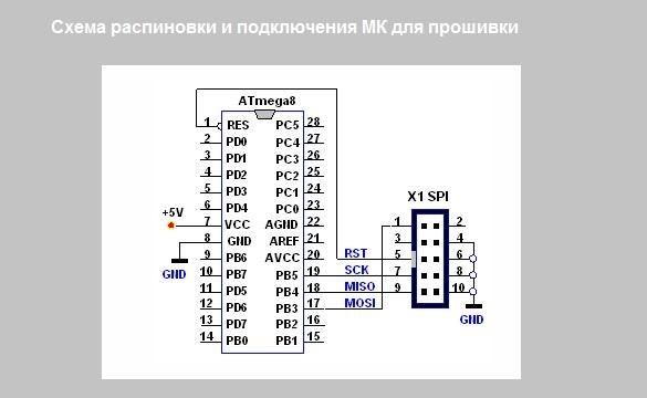
In this figure you see: The pinout diagram of the MK legs for connection and firmware.
Point 1. We will prepare everything necessary for the manufacture of a timer.
The most mandatory radio components of the circuit, the rest can usually be found at home, the smallest microcircuit is the DS1307.
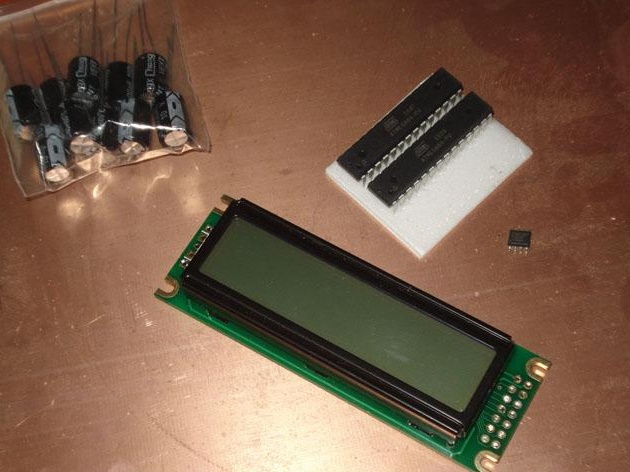
We will need such radio elements:
•
• Integrated watch DS1307
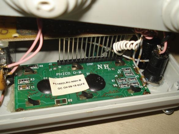
• LCD liquid crystal display
• Stabilizer 7805
• 500-1000 MF - 16 volts.
• Relay or electronic key (depending on the load that you plan to connect).
• resistance 5,1kom - 3 pcs., Variable resistor (according to LCD display manual).
• Quartz time 32768 Hz.
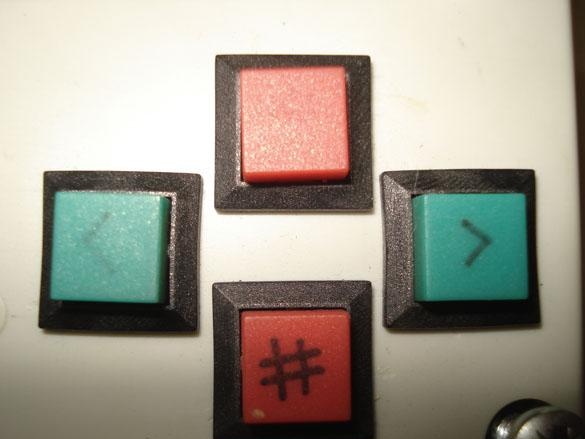
• Buttons without fixing - 4 pcs.
• 3 volt tablet battery.
• Textolite for the board.
• Small transformer ~ 220v. -> ~ 6-12v.
• Unpacking box for the housing.
+ For the programmer: resistors 150-200 Ohms. - 4 pcs., LPT port connector (for convenience, not required).
Required tools for each amateur radio:
• Soldering iron for soldering microcircuits, soldering iron for soldering passive radio components and wires.
• Tester for ringing tracks and checking radio components.
• Tin, rosin.
+ Laser printer (for making a circuit board or other method).
Point 2. Let's start manufacturing.
We will do the timer according to this main scheme.
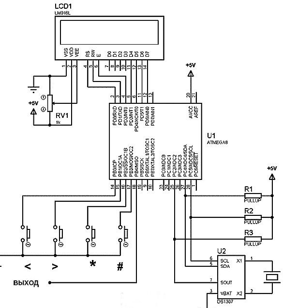
As you can see, there is no diagram of the power supply unit and the output executive device, this is because maybe you decide to use a remote stabilized power supply, and it is also not known what load you plan to connect, therefore, everyone should choose the executive device for their own technical requirements.
Personally, I used my BP timer and actuator on a transistor and relay.
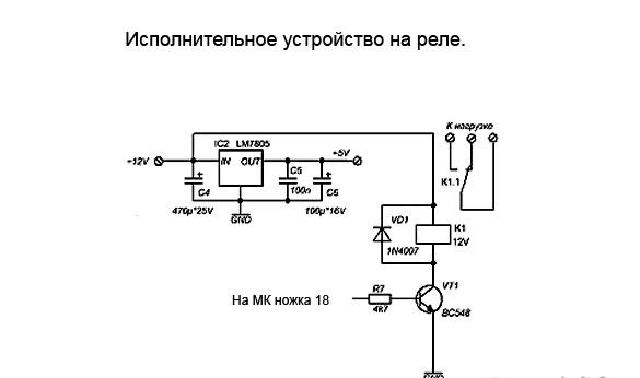
But you may want to use triacs, thyristors and triacs as an actuator; options for such circuitry are shown below.
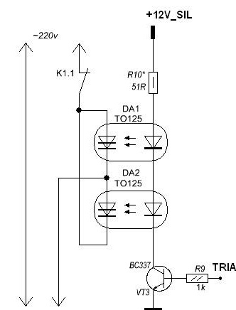
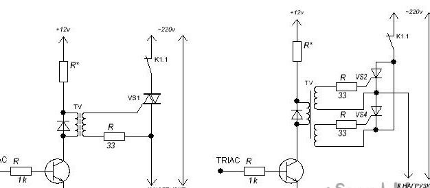
They are more compact (without a radiator), but less powerful than a simple relay.
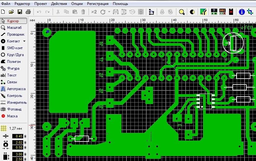
In accordance with the main circuit diagram + PSU + IU and analysis of the mounting dimensions of your box for the case, as well as the dimensions of the selected radio elements, we design the shape, size and pattern of the tracks on the board. For this, it is convenient to use the Sprint Layout program.
For my device, I got such a simple board.
The resulting pattern can be transferred using a special marker or using the LUT technology (using a laser printer and iron) on a copper layer of textolite. If you have a Brother laser printer (like mine), then it is better to abandon the idea with LUT right away, because of the refractory toner ~ 400C used in it instead of the usual ~ 200С, by the way, I used to stupidly buy this printer specifically for LUT :(. , therefore, as a result, my board is drawn with a marker.
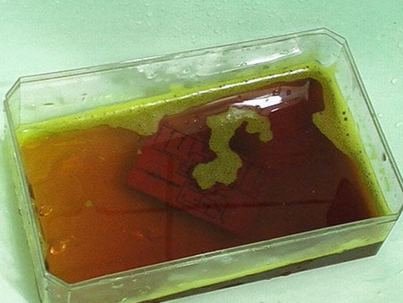
The pattern applied to copper is etched in a bath with ferric chloride or any other special solution.
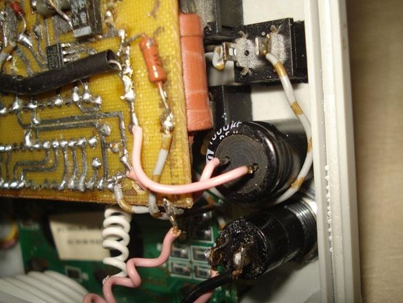
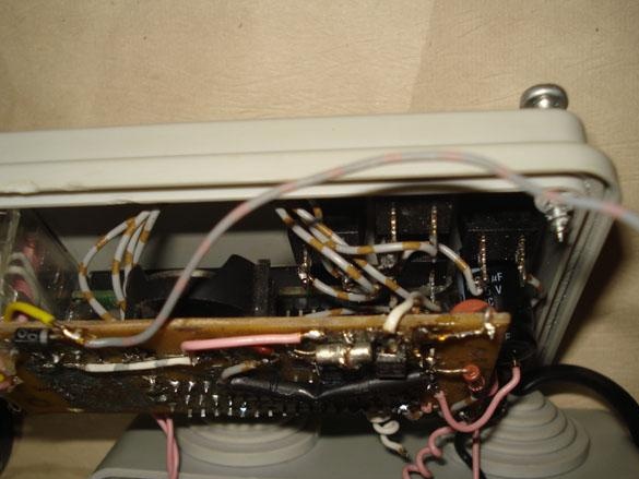
We solder the parts to the finished board according to the scheme, we pay special attention to when mounting and soldering the microcircuit of the clock and the quartz element. The length of the tracks between them should be minimal, but it is better to use micro quartz from a watch and solder it directly to the legs of the MC watch. We fill all the free space next to the MS of the watch and quartz with the body pads (GND). A battery is needed to maintain the watch in working condition while disconnecting from the mains. If for some reason you did not install this battery, then put the plus wire on the case, otherwise the watch just won’t work.
We flash the microcontroller with the programmer or with the help of 5 wires.
*Firmware*
The author of the firmware is especially for convenience (for which I thank him) and did not change the factory fuses, which greatly facilitates, without troubles, the firmware for a beginner radio amateur. If MK has not been used yet, a new one from the store, then just fill in the firmware and that's it, but if there are already changes in the fuses, you need to set them like CKSEL = 0001. Everything else is simple and needs no explanation.
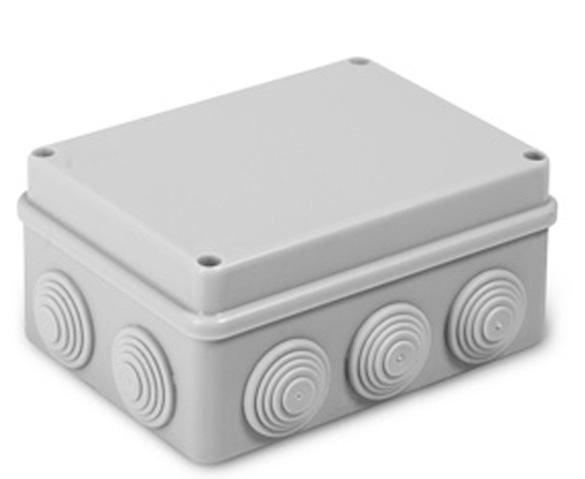
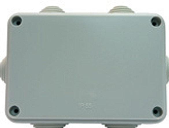
Item 3. Assembly.
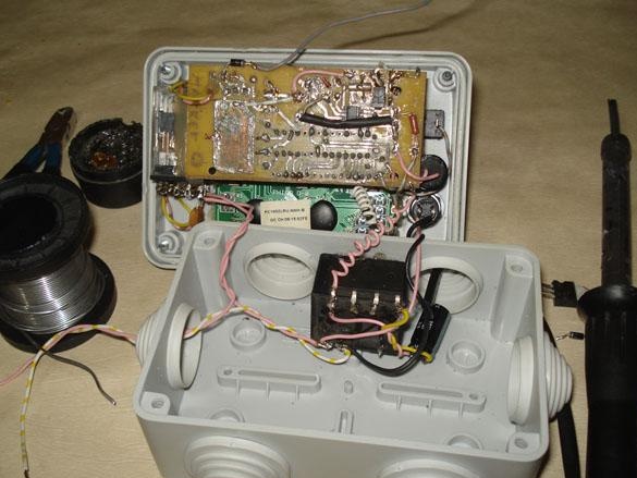
For the case, it is very convenient to use plastic junction boxes, they come in different sizes and shapes.
We fix the LCD screen into the cover cut by the knife with the help of hot glue from the gun.
Cut the protruding glue.
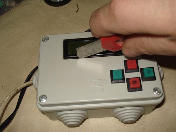
We place all the nodes inside the case, constantly checking how the lid closes, if necessary we transfer or bend the interfering ones. Everything is fixed on hot glue.
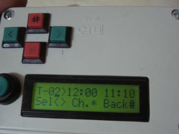
We supply power to the assembled circuit, such an image should appear, the clock starts from zero.
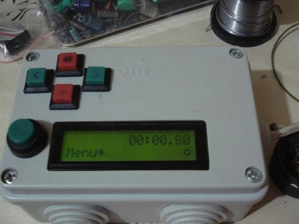
The menu is controlled by four buttons.
The menu consists of three items, CLOCK - setting the clock, TIME - setting timers and RESET - resetting all set timers.
First we go (*) to the clock menu and set the exact time.
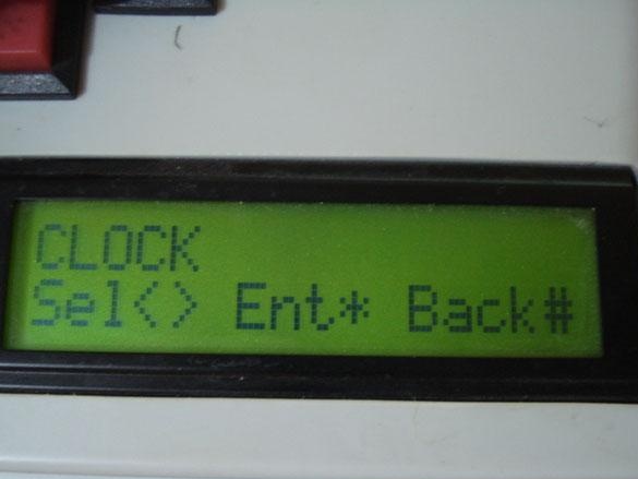
Hint for the control buttons in the bottom line of the display, each menu is different, so there is no need to describe the buttons.
Now everything is ready to correctly set the temporary timer entries, after pressing the trellis, the program is written to the permanent memory of the MK.
In the video at the beginning of the article you can see more about the menu.
I use this timer to water hydroponics.