

1. Not expensive
2. High-quality sound
3. Few parts and easy to assemble
4. No configuration needed
Good day the inhabitants of our site!!! =) Today I will bring to your attention an amplifier that I collected from (practically) rubbish lying in my zashashnik. Long ago working at the service station, we often removed amplifiers from cars, since they arrived without tape recorders (and standard two-single mayfuns often went through an additional amplifier) and in order to put a regular tape recorder we had to dismantle the amplifiers from them !!! I have since then a couple of amplifiers with such chips as. A lot of time has passed since then until my sister asked me to do something for my laptop to play in the courtyard with acceptable quality and loud sound, since 2 pcs speakers were idle at home!
As soon as I drove something similar to “Amplifier on LA4708” in Google, I was thrown to foreign sites where there was a ready-made solution for denyuzhku. There were no schemes. I downloaded Datashit, soldered a sketch on it and the sound was just UG !!! Climbing a little more on sites, from different schemes it was decided to create something good that really would sound, and not fart and distort the sound. As a result, I used the Internet, forums (thanks to them) and made a simple, improved scheme with my head:
Here, half is taken from the datasheet, and half is just from people and schemes that have been tested for years !!! If you look at the circuit, then the capacitors C3 and C4 are storage, standing at the output of the amplifier, there is simply no way without them (the sound seems to disappear at high bass and is not enough to swing the speakers). In the amplifier where I soldered this microcircuit from the input, there was a storage choke (but I was too lazy to wind it up, since the standard one was a bit too big, and in the picture at the very top it wasn’t) it was decided to do without it !!! The nominal value in microfarads and capacitor C7 was increased to 3300 microfarads, additional capacitors were installed at the input from the sound source, and instead of the zener diode, I put a heel on 5V to the 5th leg (since it was at hand) Well, here are all the components that we need:
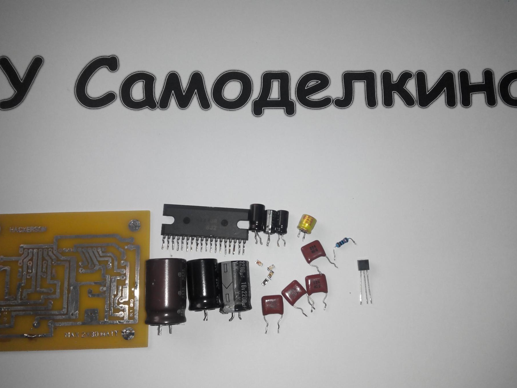
Unfortunately I forgot to add a couple of smd capacitors to those that are at the input, but about the size is clear =) I must say right away that the capacitors are C1, C2, C5, C6 (Mylar or polypropylene). Next we tin, drill, solder elements, from small to large. Unfortunately, the cache was malfunctioning and the photos disappeared with my tinning and soldering = (Only the result and test remained for 2 weeks =)
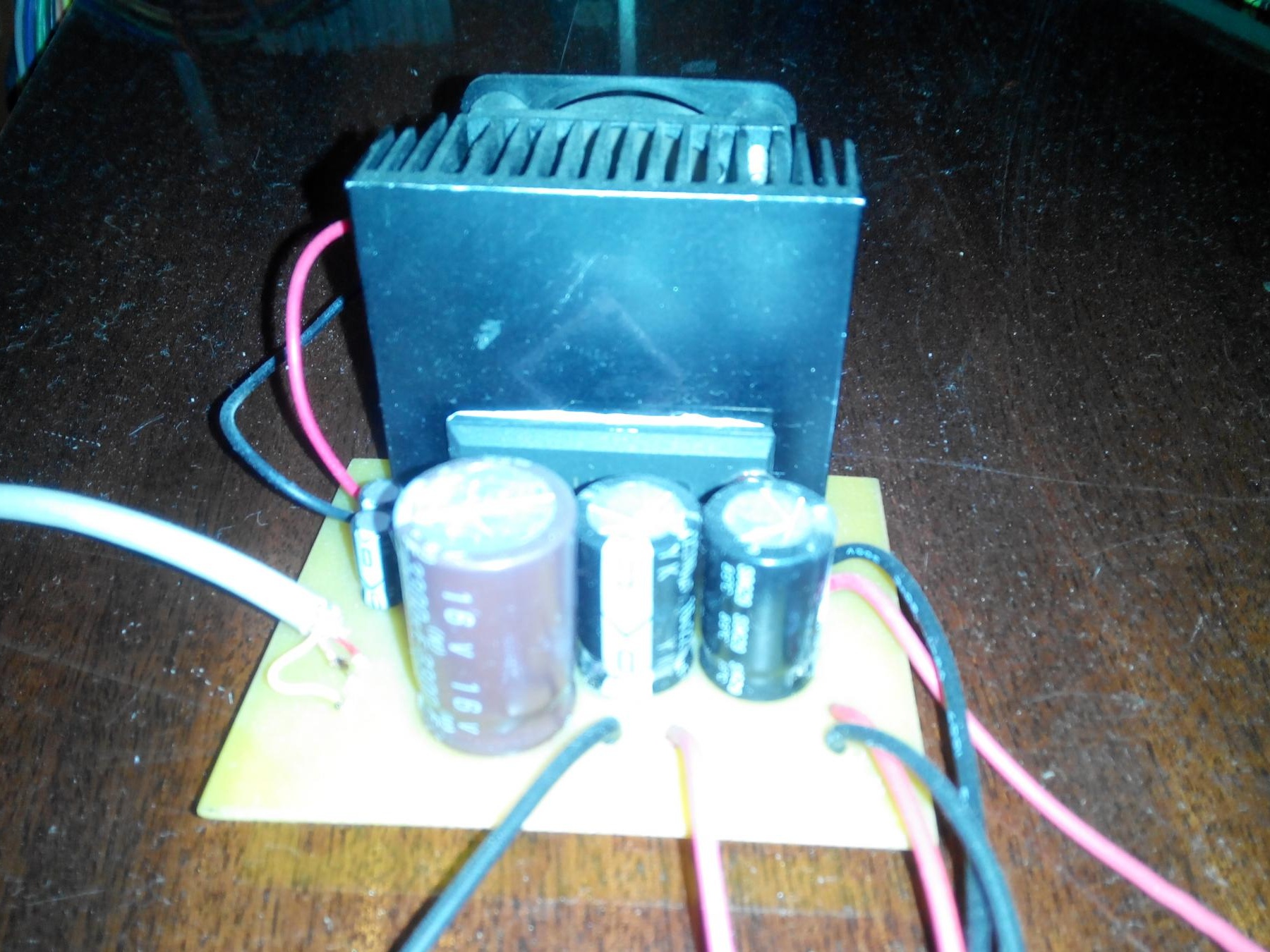
Put on active cooling, the signet will be provided !!! My advice is not to set the active, but rather to increase the area of the radiator. Below the signet:
Test driver =)
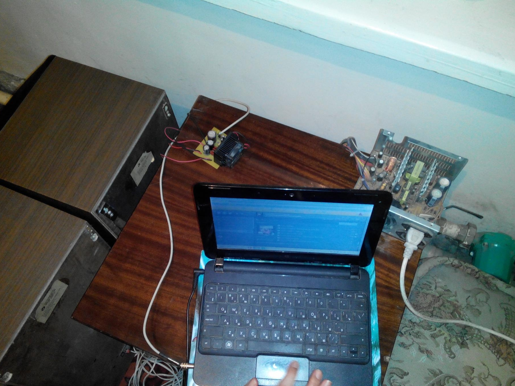
The amplifier delivers its net 20-30 watts per channel! Tested on AC35! Keep in mind that this is a tip, there are no volume controls !!! Before starting, the volume is at a minimum !!! I started the amplifier from a regular computer PSU, it still works like that (there’s no time to stick it in the case =)
Archive with circuit and signet
All success in the assembly and of course new ideas: wink: