

Sitting at home and bored, I remembered my old dream: to control various devices (lighting in the house, a lock on a wicket door, blinds on a window) without getting up from a computer, and when writing and own software, it can be done from anywhere in the world via the Internet, after spending a couple of hours on the Internet, having reviewed a bunch of amateur radio sites and forums, I chose a device option that is more suitable for me, as for a beginner amateur who recently got acquainted with the properties of a transistor, diode, and other elementary radio elements and absolutely nothing go not understanding in microcontrollers.
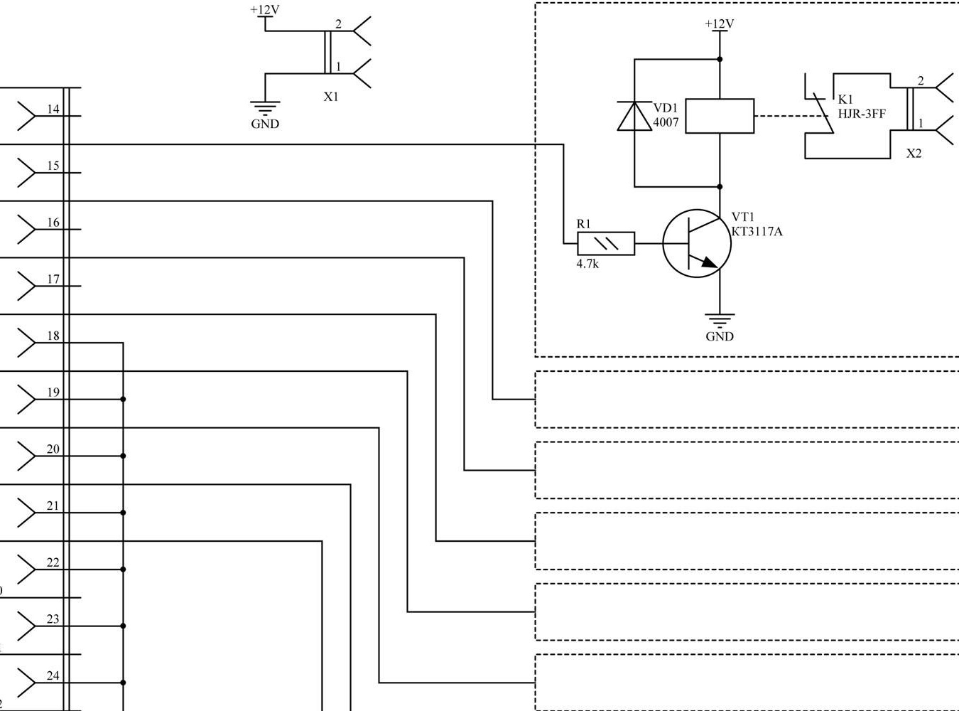
After reviewing the circuit which consists of a resistor, transistor, relay and diode, I decided for myself that I can easily cope with this task, and modify it a bit, namely adding LEDs for convenience and indication.
The only drawback of this analog circuit is that the load control is done through the LPT port of a desktop computer with an outdated motherboard, but since this circuit is very easy to repeat and I have an old desktop computer that no one needs, which can serve as a great start to create a smart home , then I just could not miss this little scheme.
To create an LPT-controlled outlet, we need:
• Textolite
• LPT port side “B” (opposite to the side that is inserted into the computer) I picked out from the board of the old printer
• I took 4 HJR-3FF-S-Z relays (12V winding, 10A switched contact, 250V AC), although the board is wired for 8 of these relays. 4 things
• Diodes VD 4007 4pcs.
• Transistors KT3117A (I took their Chinese counterparts, since they are cheaper, I have the same characteristics) 4pcs.
• Resistors, I used SMD resistors, they are easy to install because they do not need to drill holes with a nominal value of 4.7 Kom
• Power supply for 12V. I took the power supply similar to charging from a mobile, it turned out to be 12V at the output.
• Outlets I took 4 outlets from old military equipment
• Wires
• 5 LEDs for indication (4 indication of relay activation 1 power indication)
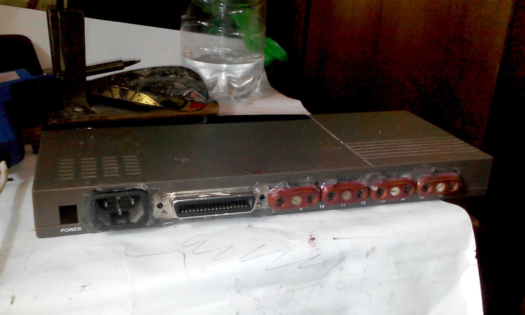
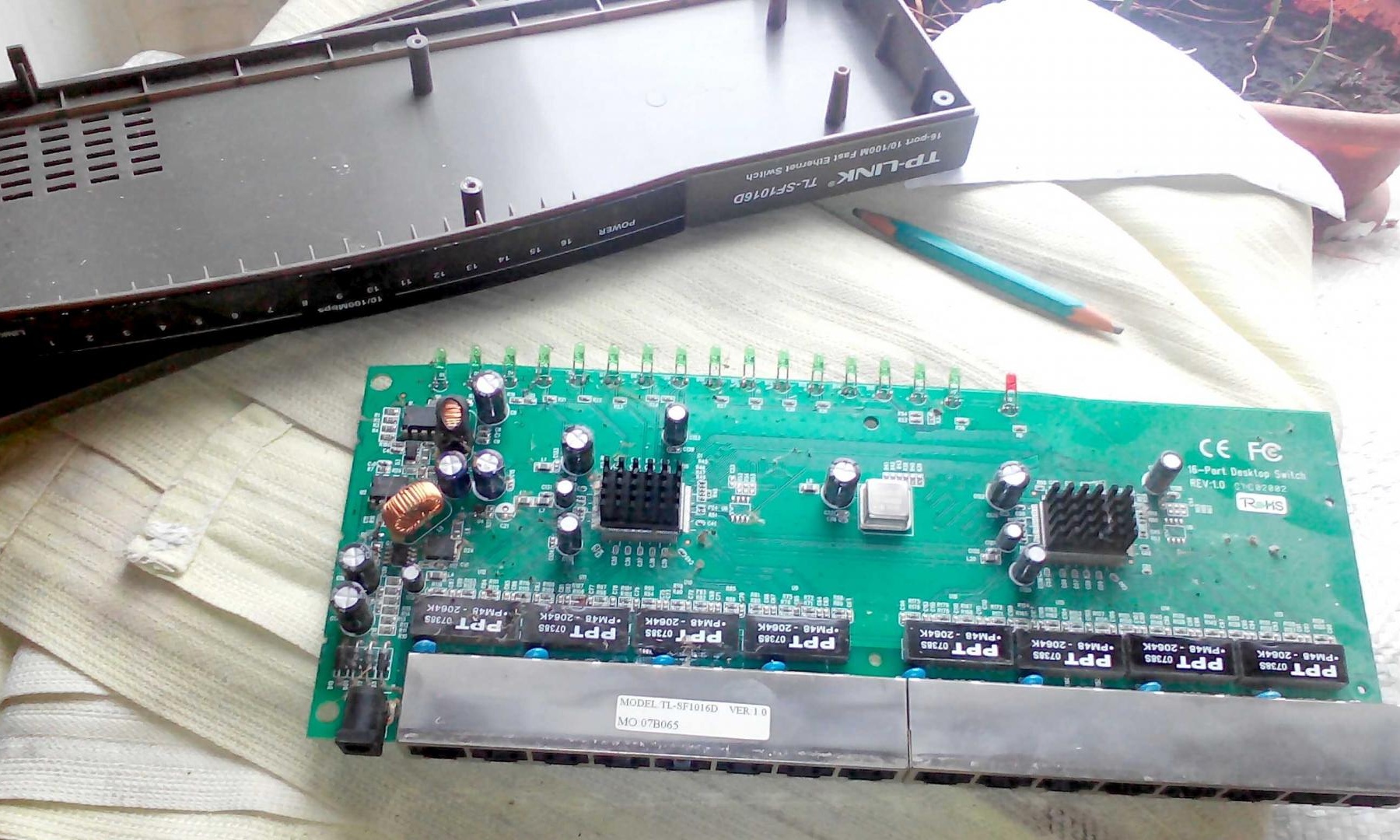
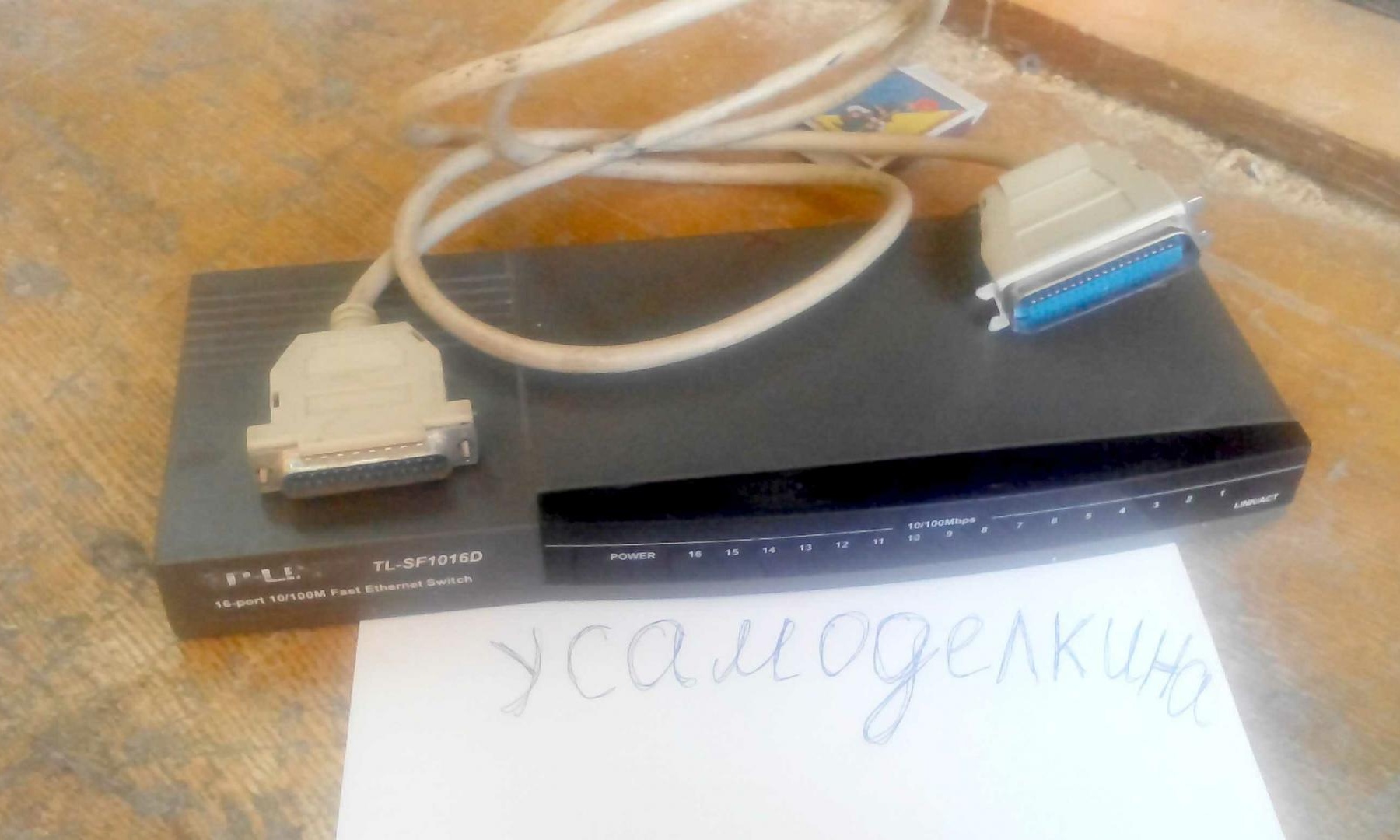
• Case (I took from an old idle switch for 16 ports)
• LPT wire
• Soldering iron and soldering accessories
We will start by developing the board and etching it. I was lucky to find a ready-made printed circuit board in the “.lay” format, for its opening I used the program “Sprint-layout_6.0”.
We print the board on a laser printer and translate it to textolite, then it must be etched and pooled.
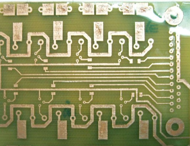
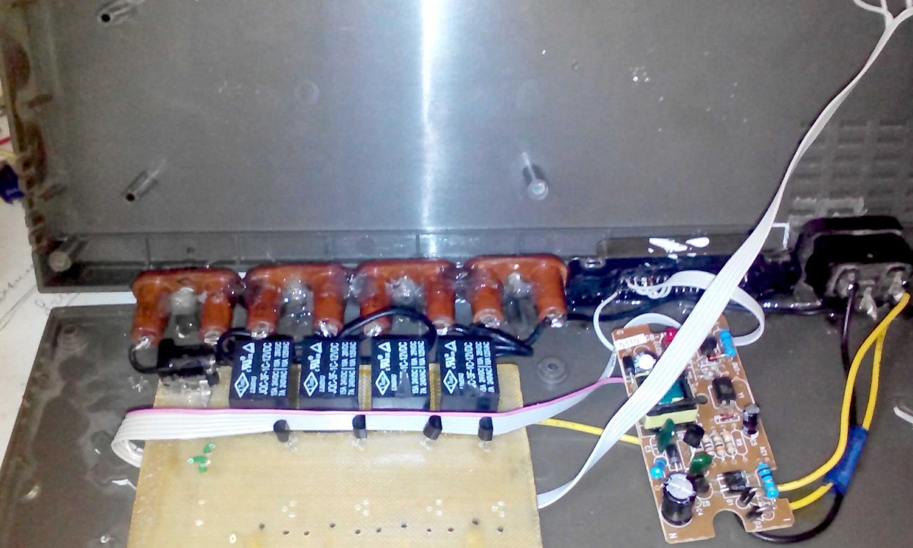
Next, we solder the holes for the relays and transistors and we can proceed to assembly.
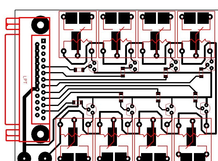
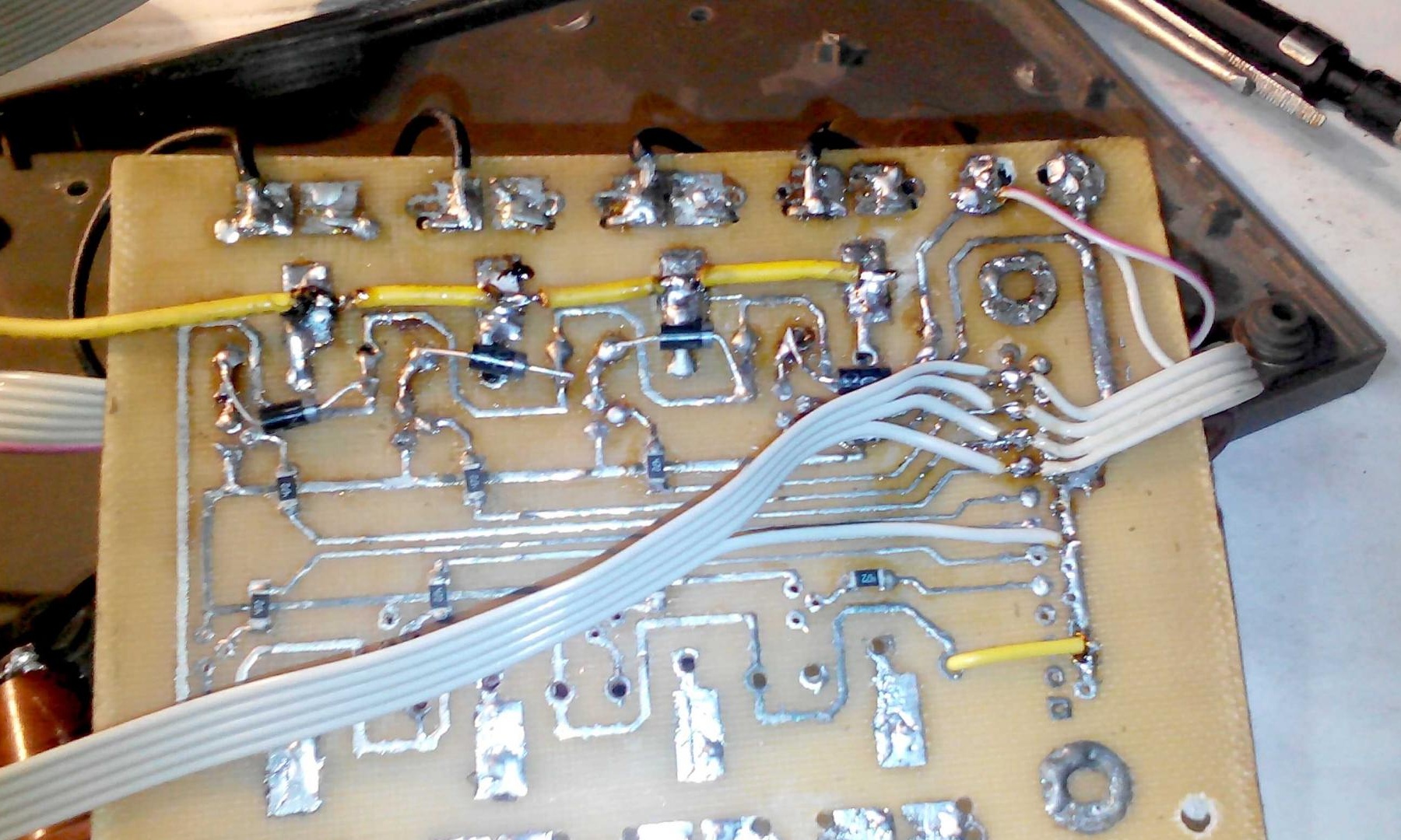
We solder the elements according to the scheme or look at the picture in the "Sprint-layout_6.0" program, I personally like the second option more.
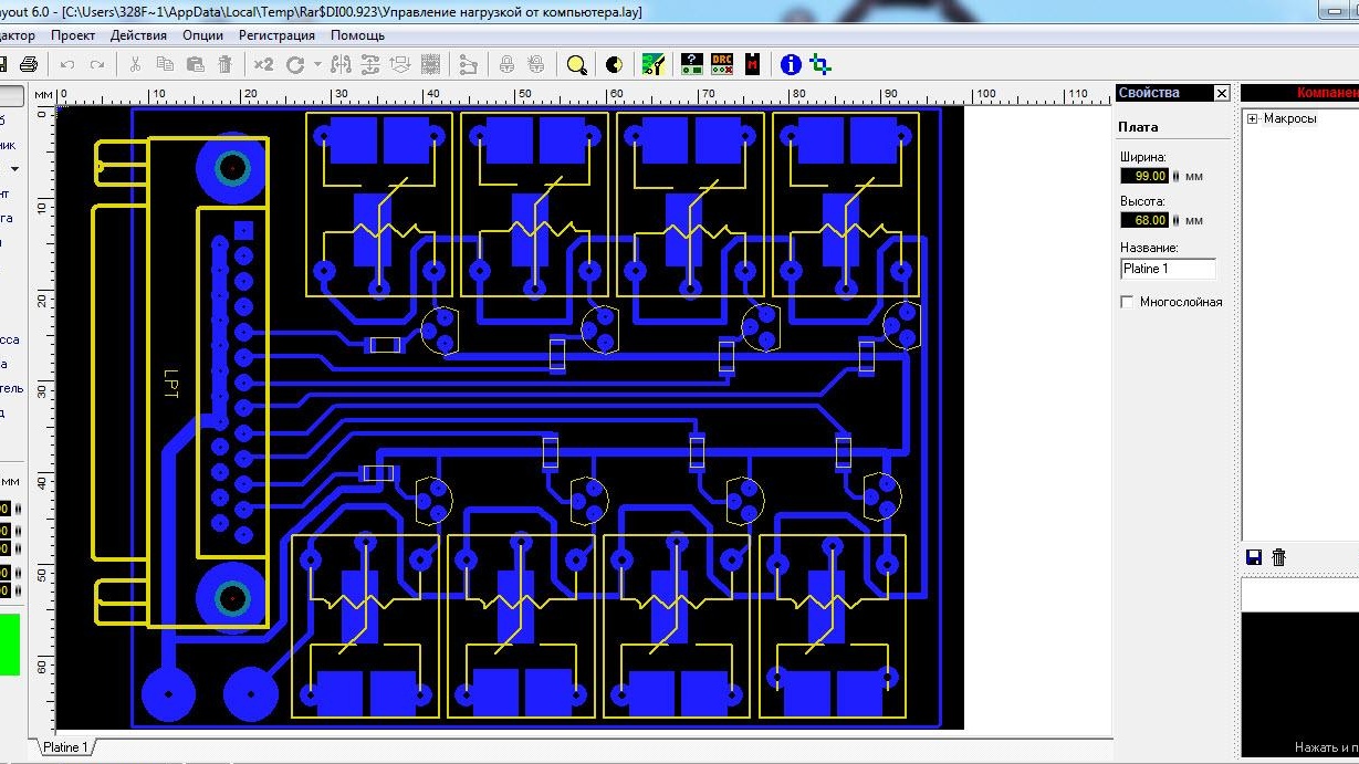
Here is what you should get
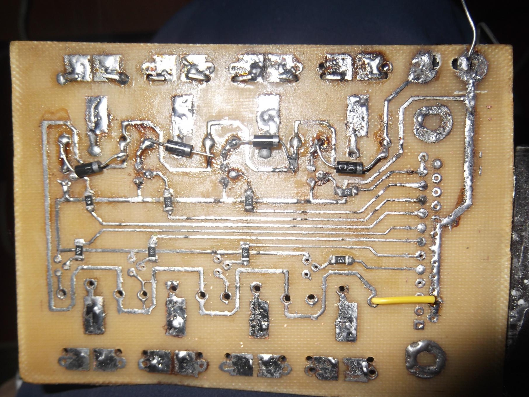
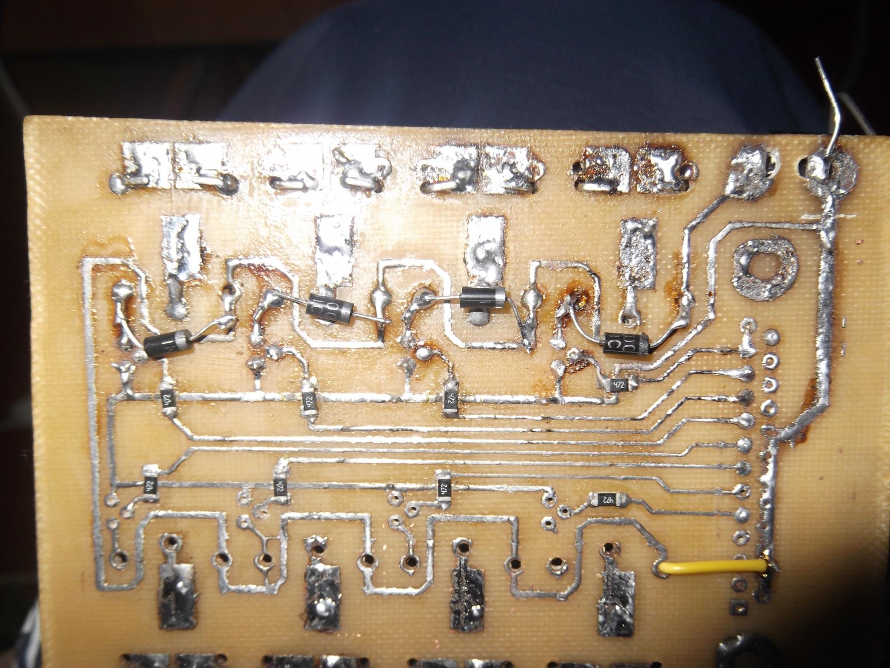
I almost forgot, it is necessary to install a diode to protect the transistor from reverse voltage surge, throughput direction to the plus. The board is almost ready.
Now you can begin to manufacture and assemble the housing.
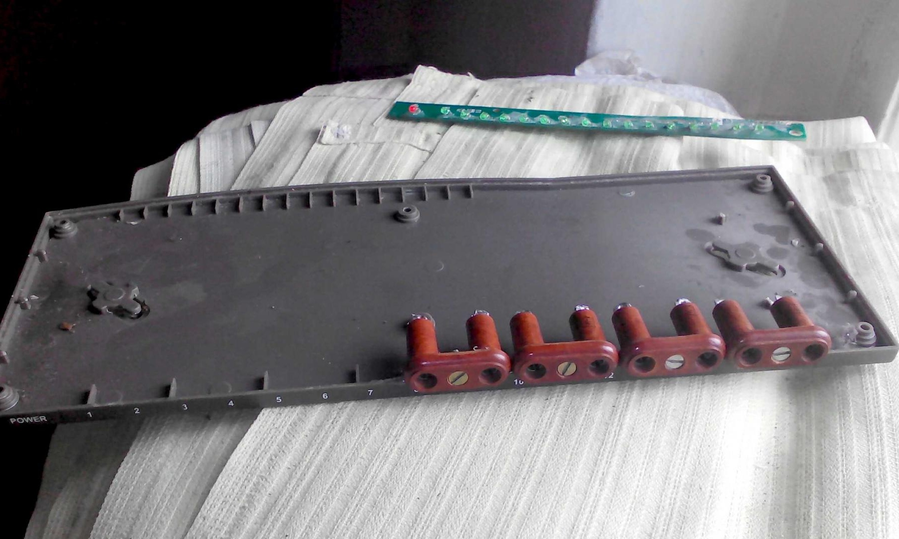
First of all, we disassemble the old switcher and throw the board out of it)

The second thing is to figure out the placement of boards, sockets, ports in the case.
As it turned out, the LPT port and connector for connecting 220 did not fit in size and I had to file the case a bit
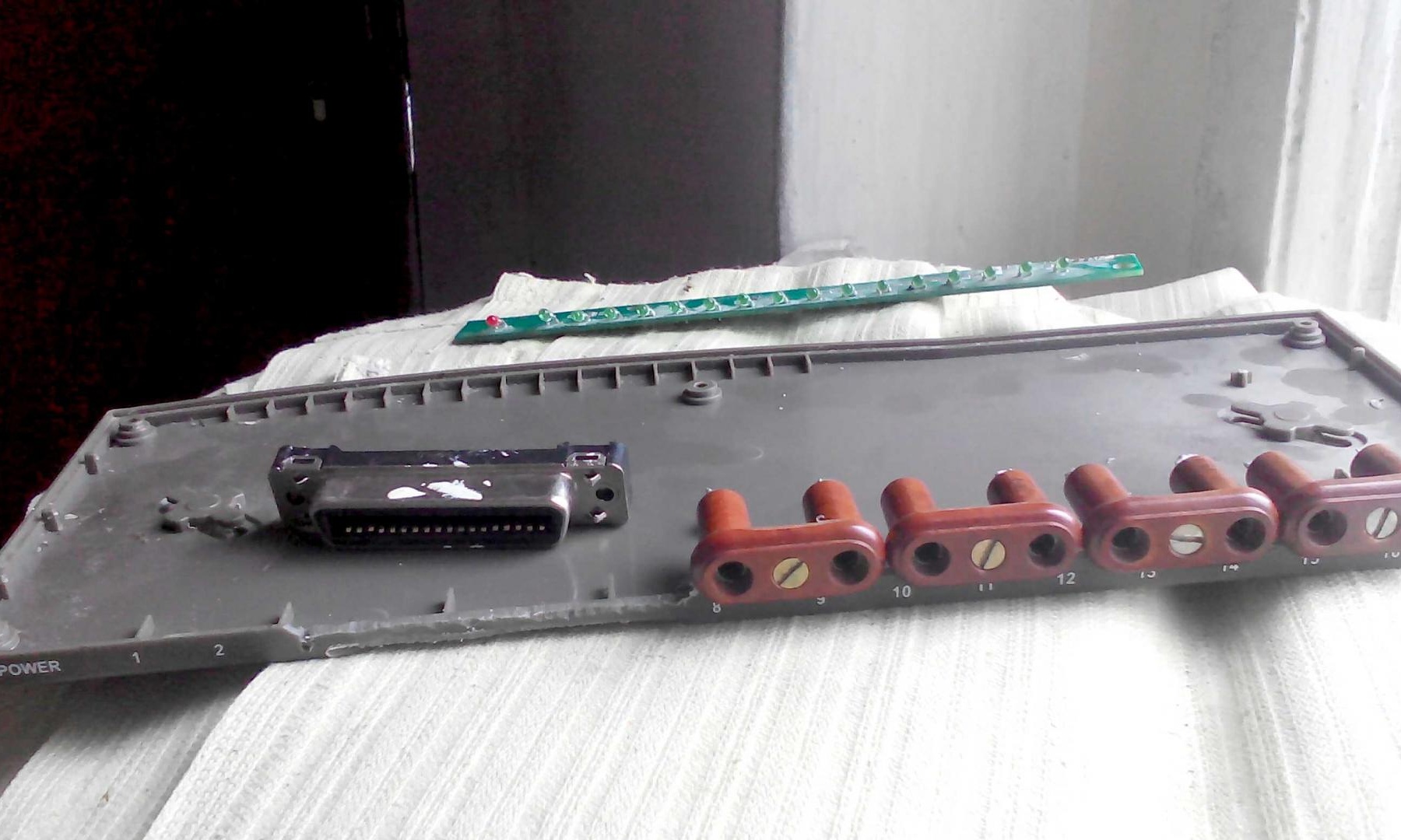
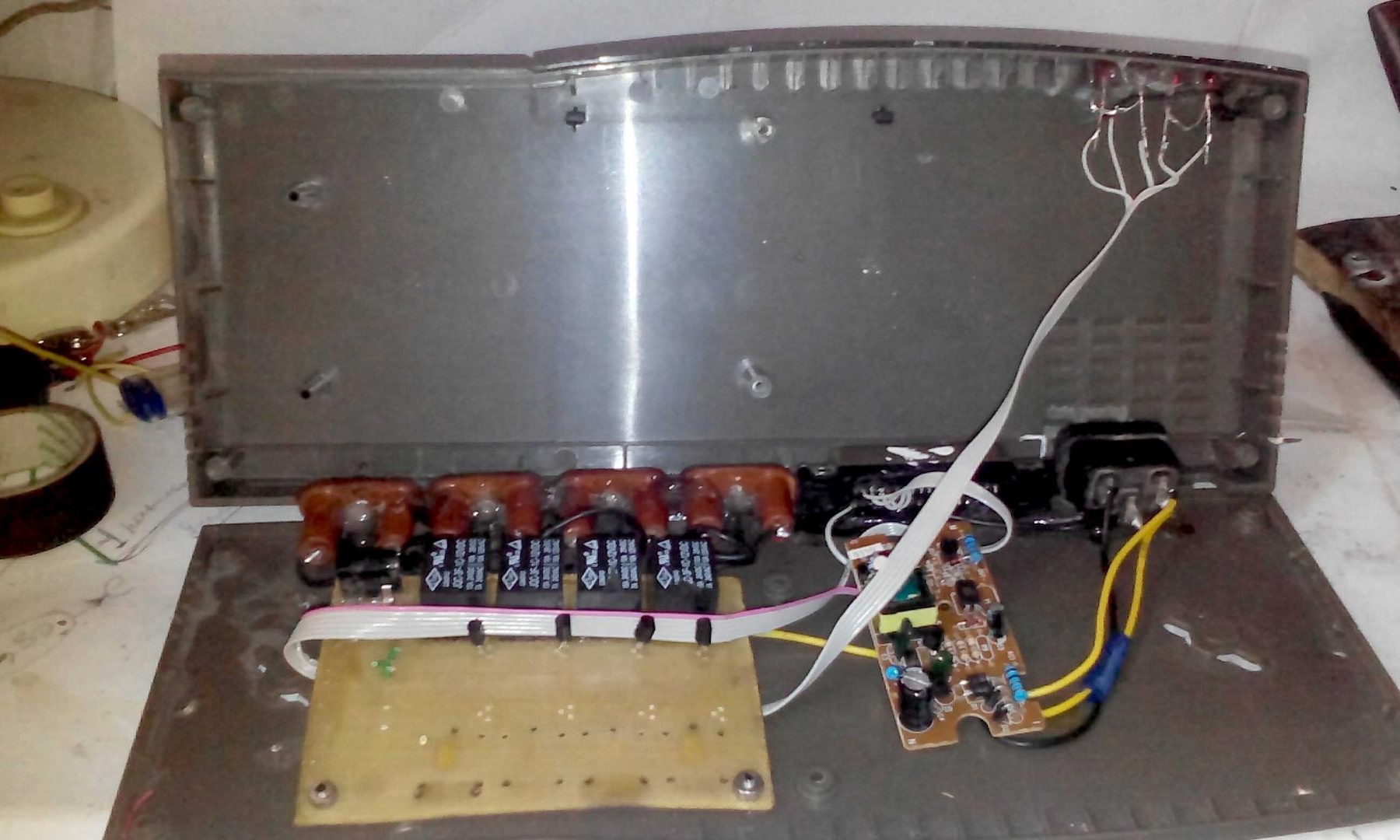
We put everything in place, fill it with hot glue and close the lid of the case to make sure that everything is fine and it fits.
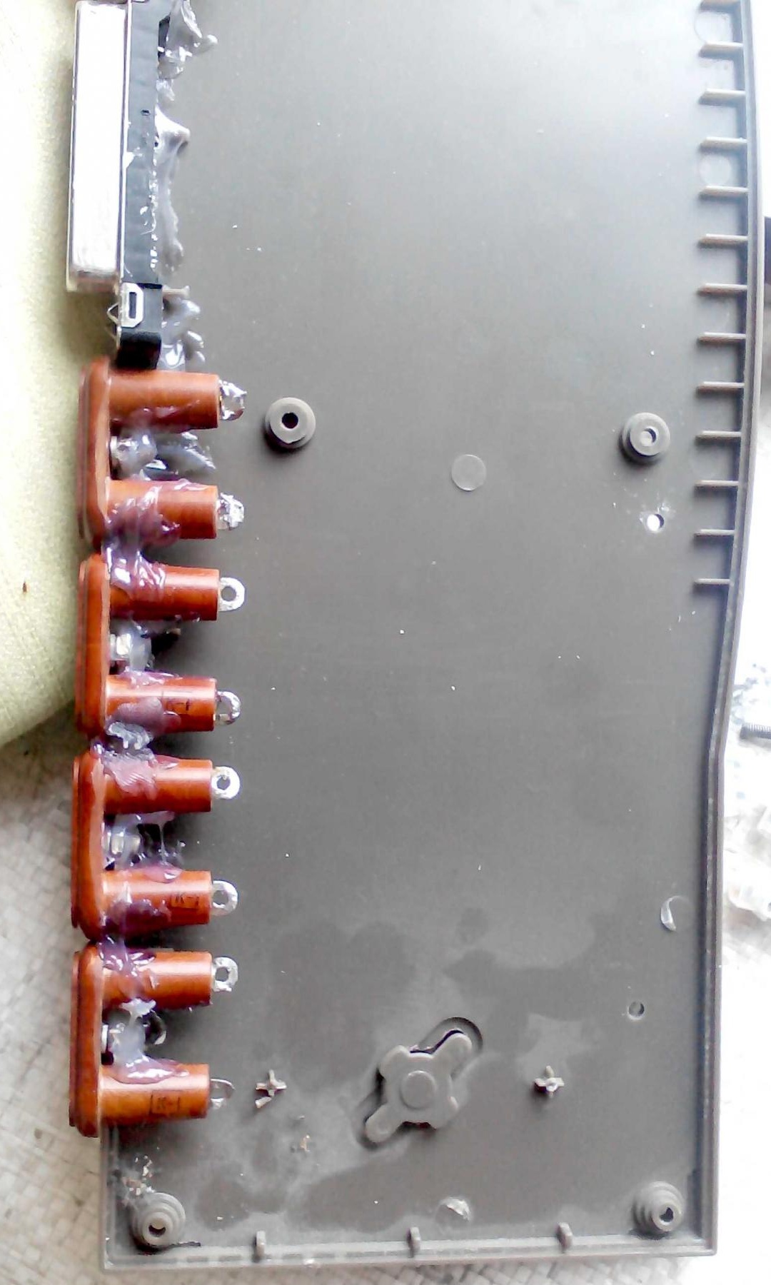
We return to our board and solder control wires to it in a hinged way, which in turn solder to the LPT port glued to the case.
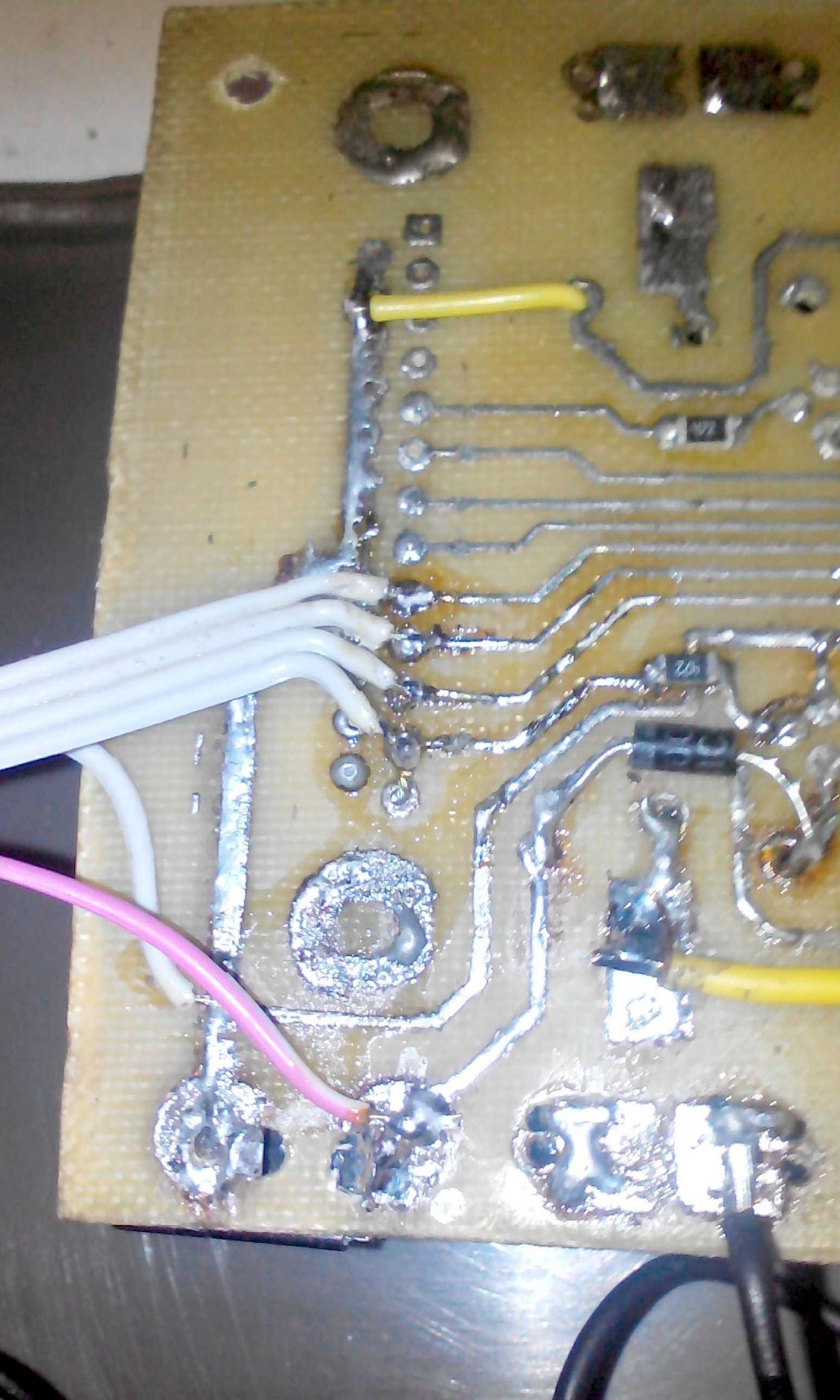
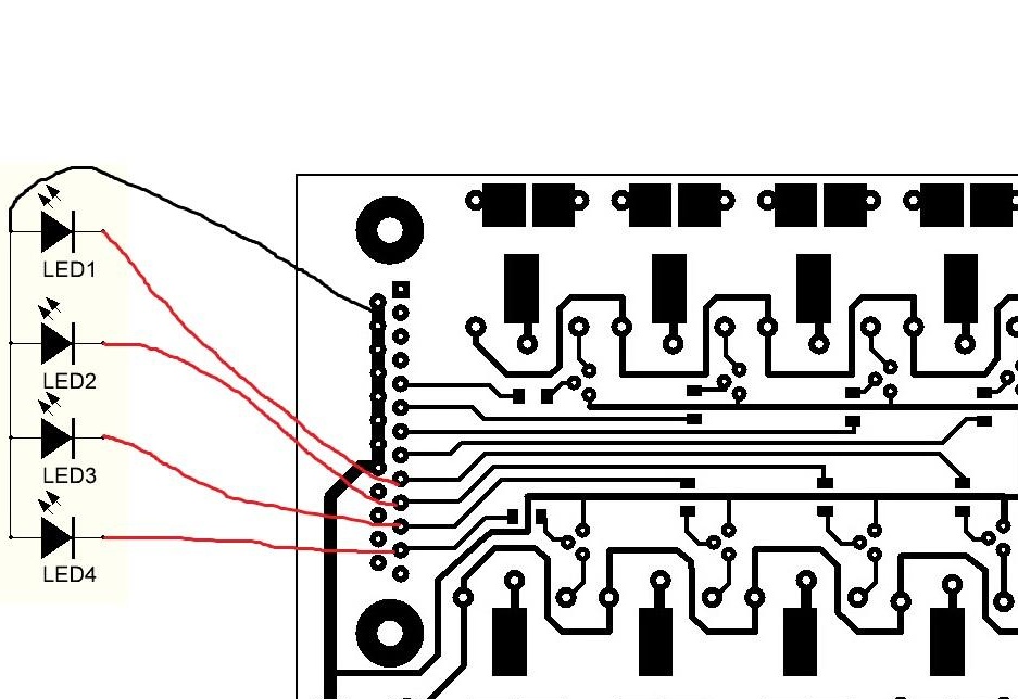
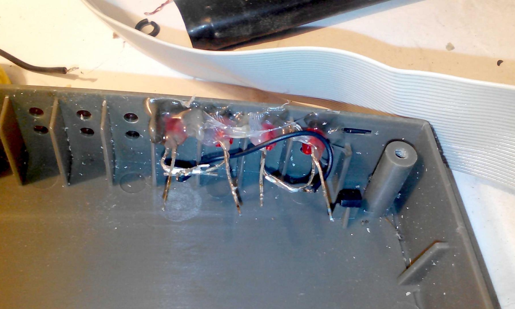
After the wires from the LPT port are soldered, you need to solder another 5 wires for the LED indication, I installed the LEDs in place of the LEDs that showed the presence of wires connected to the switch.
Soldered wires according to this scheme
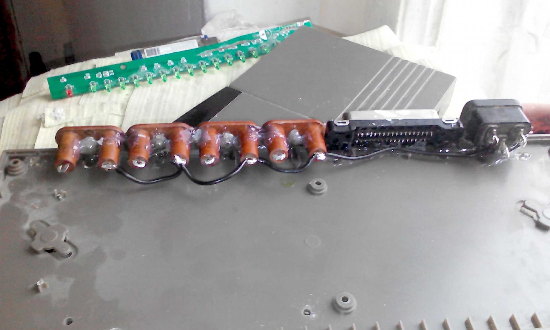
Here is what you should get
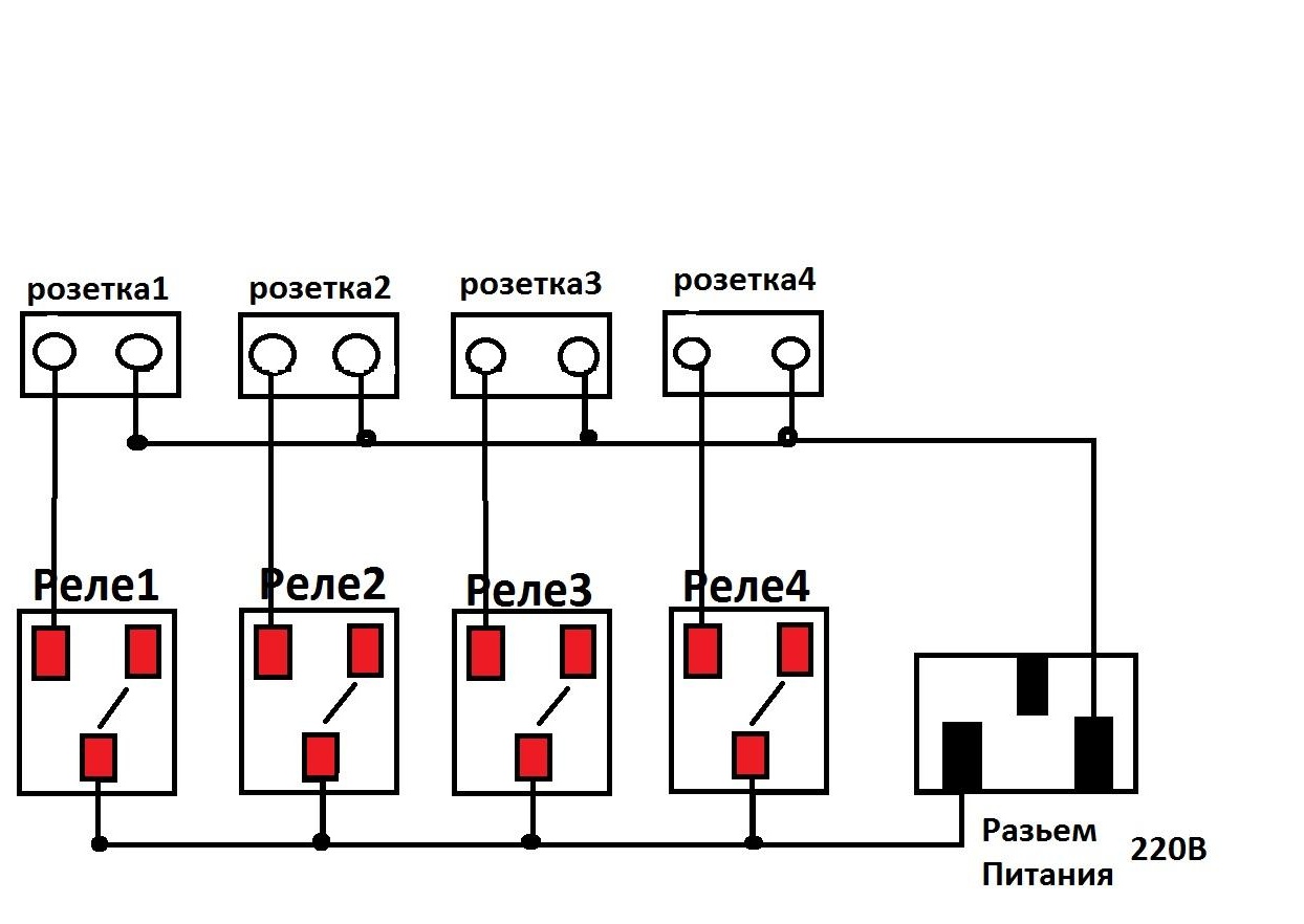
Next, we combine all the central relay terminals, terminals on sockets and solder to the 220V input connector
Here is a visual diagram of connecting wires with voltages 220V
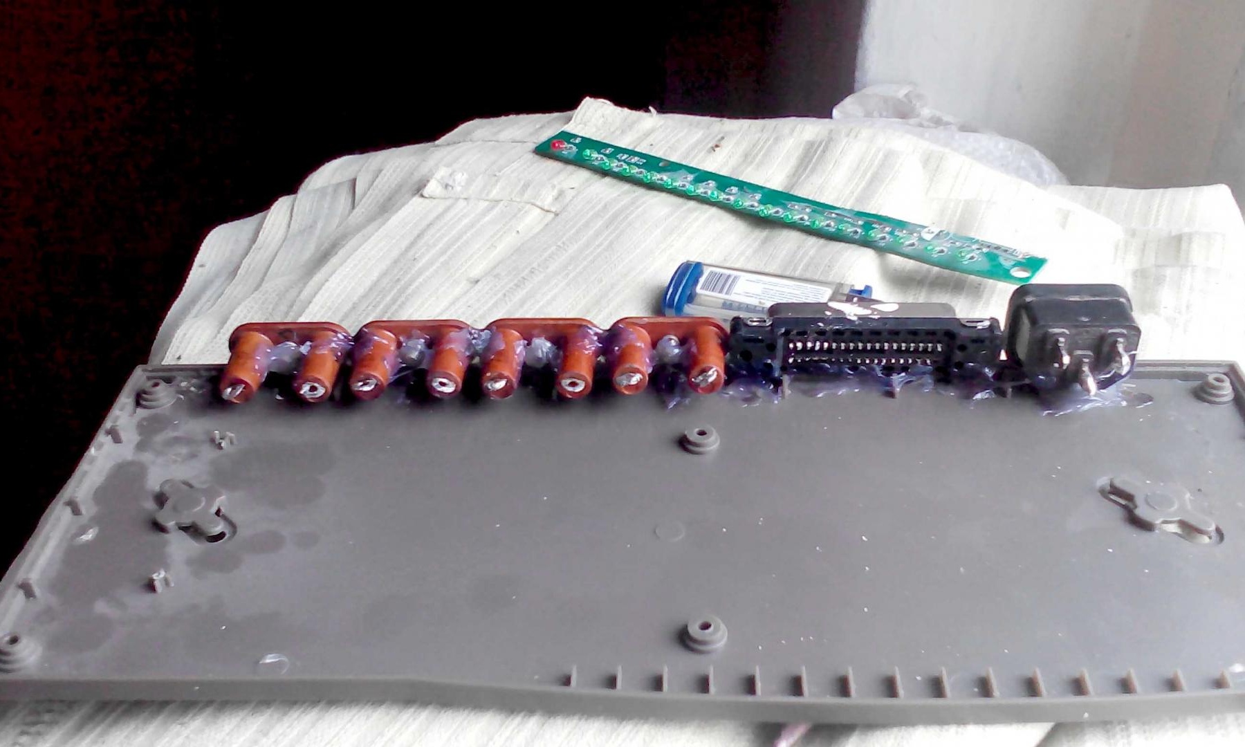
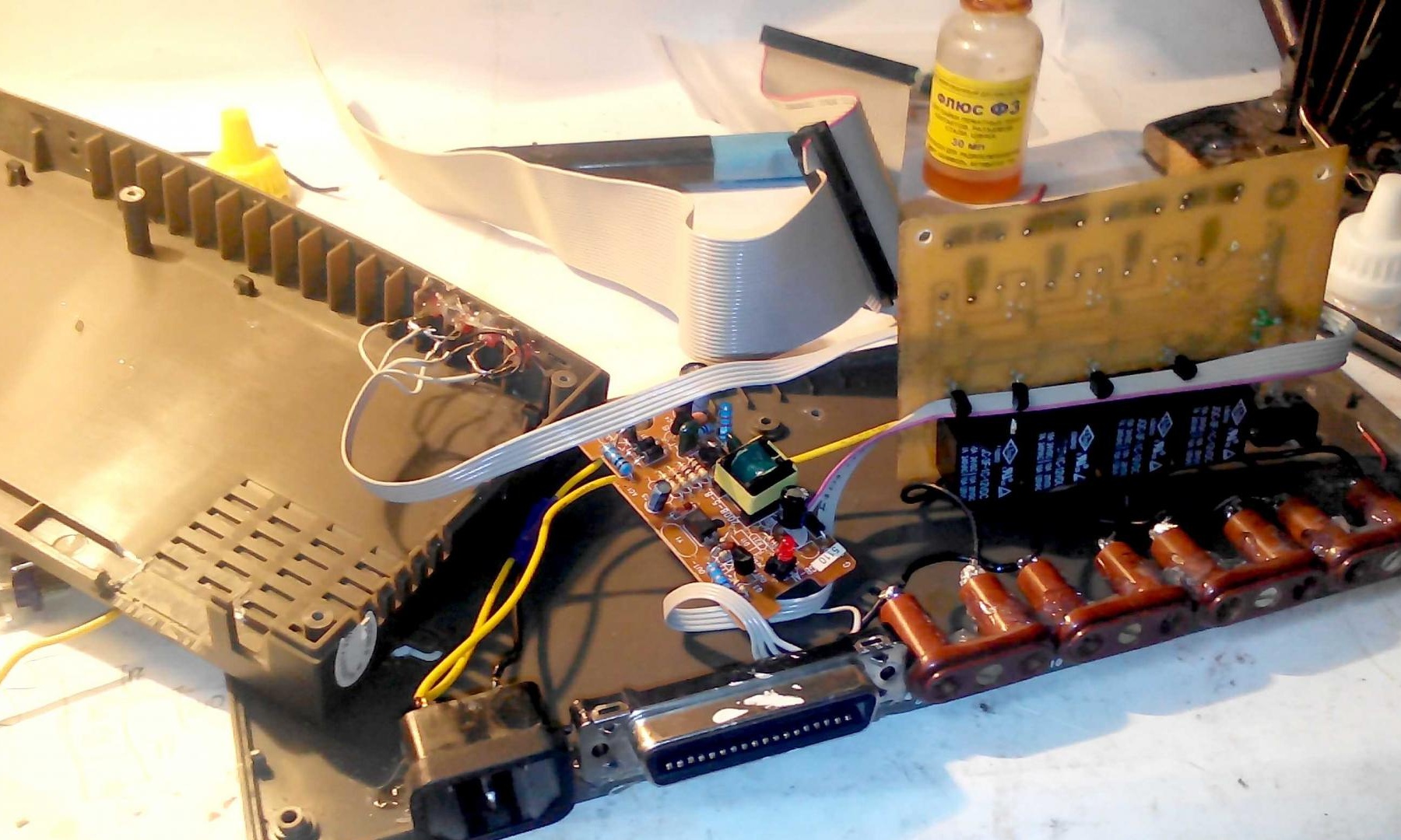
It remains for us to connect the control voltage for the 12V relay, we will take them from the power supply (I don’t know why, just lay in a heap of unnecessary rubbish)
We disassemble the unit, solder off the standard wires and solder the wires that will record the relay to 12V voltages through the transistor.
The principle of operation of a transistor amplifier, I think, you know. 5V is supplied to the base, the transistor opens and 12V voltage is applied to the relay, which in turn commutes the load more.
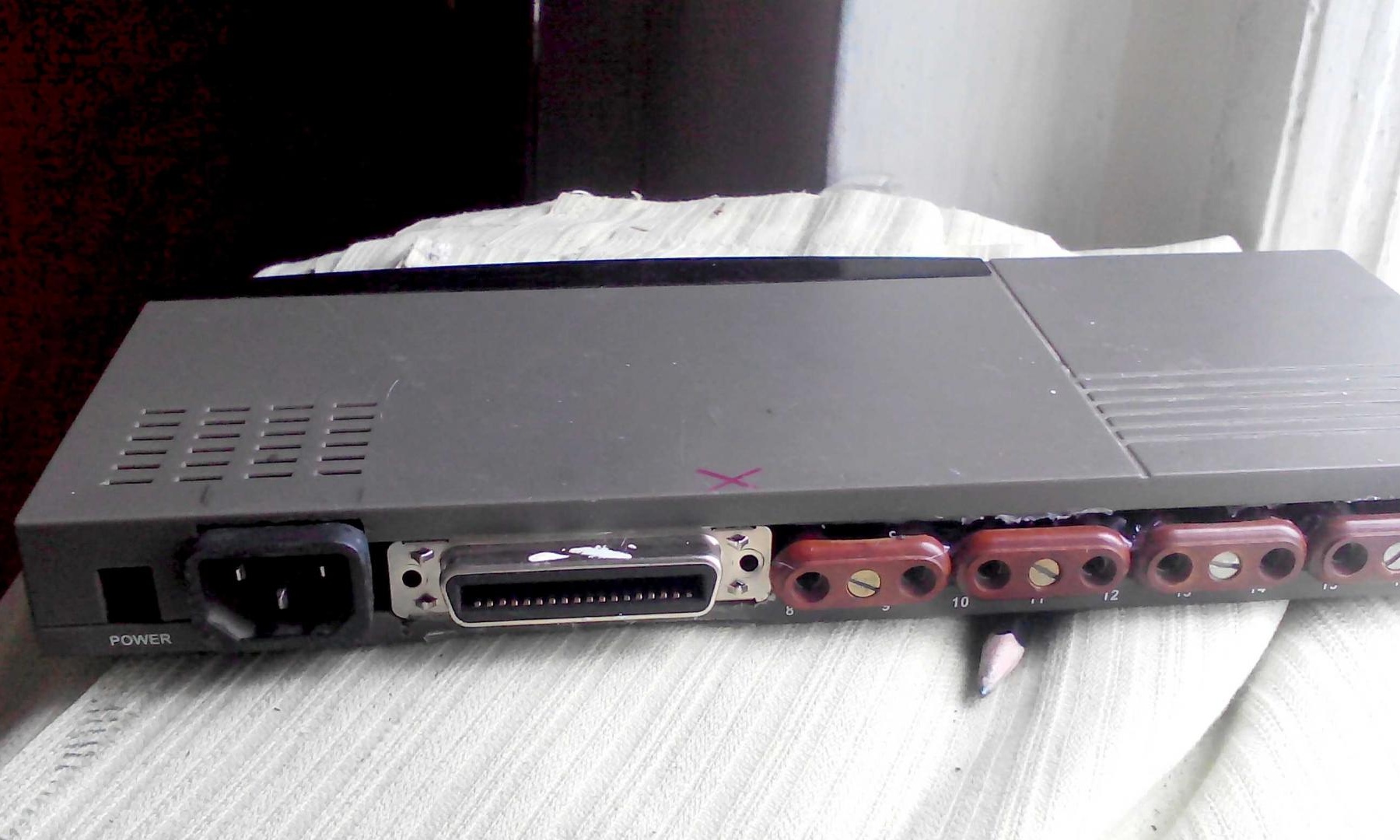
We connect the power supply, we sit the boards on the screws and you can proceed to the final stage - assembly
When the assembly is finished, you can start testing)
Launch the LPT-Control-Panel program
We see a window in which loads are displayed, if we correctly assembled the circuit, then when we click on the load we need, the corresponding load will turn on.

For the test, you can use ordinary incandescent lamps.
We try, click "Load 1" - lamp number 1 should light up

Etc.
I have 4 relays, you have the opportunity to connect 8 relays and, accordingly, 8 loads.
Thank you all, good luck!
Here is the archive with the program and the circuit board