

The first scheme (Fig. 1) is based on a reprint in the journal Radio (1970, No. 10 from radio serkehen elektronik).
To improve the accuracy of maintaining the temperature and reliability of the power unit, changes and additions have been made. Transistor VT2 is loaded on a resistor, not a relay. Added resistors R9 and R10, transistor VT3, a heater switching circuit through a thyristor included in the diagonal of the diode bridge.
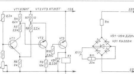
The temperature controller is assembled according to the bridge circuit. The thermistor is included in one of the shoulders of the bridge, the remaining shoulders of which consist of resistors R4R5-R6-R2R3. Power is supplied to one of the diagonals of the bridge, and the base – emitter of the transistor VT1 is included in the other.
The voltage across resistor R6 is approximately 5.6 V. If you add the threshold voltage of transistor VT1 to it, a switching voltage will be obtained.
Circuit work. When the temperature in the incubator is lower than the rated voltage, the base on the basis of VT1 is small, the transistors VT1 and VT2 are closed, and the transistor VT3 is open. Current flows through the relay winding, its normally open contacts are closed, they include a thyristor control circuit. The thyristor is open, the heater circuit is on, and the incubator is heating.
When the set temperature is reached, the resistance of the thermistor decreases, the voltage based on VT1 increases. The transistor VT1 opens, through the circuit R6, the emitter-collector VT1 junction, the current passes through the resistors R5R6. A voltage drop is created on the resistor R4, it is applied to the base with a plus, and minus through the resistor R7 - to the VT2 emitter. Transistor VT2 will open and, by an open junction, the collector-emitter will connect the VT3 base to its emitter through the low resistance of resistor R7. Transistor VT3 closes, the relay de-energizes, its contacts open the control circuit of the thyristor, the thyristor closes, the heater turns off.
Variable resistor R3 is used to set the required temperature.
To power the circuit, any stabilizer that provides a current of more than 150 mA is suitable. The stabilizer can be included both in the negative circuit and in the power plus circuit. It is convenient to use the integrated stabilizer KR145EN8B or KR145EN8D.
Details. KMT-1 or CT1-17 thermistor. The inclusion of several series-connected thermistors with a total resistance of 8.2 k is allowed. Relay RES-10, passport RS4.524.302. You can use any relay with a trip current of up to 50 mA at a voltage of 12 V and whose contacts are designed for switching 220 V. The transistor VT1 can be replaced with KT361E, KT3107 with any letter, VT2, VT3 with KT315E, KT3102 with any letter.The VD1 diode can be replaced with any of the D226, KD105, D7G-Zh series. The bridge diodes can be replaced by KD203, D246 and others with a maximum permissible current of 5 A or more and a reverse voltage of 400 V or more.
Thyristor and diodes must be installed on radiators. The power of the heater should not exceed 1500 watts.
Resistor R3 type SP-1 with a functional characteristic of type A. Resistors can be ULM-0,125, BC-0,125, MLT-0,125. Resistor R11 MLT-1. Resistor R7 type MON, TVO-0.125. It can be made independently by winding the required amount of wire with high resistivity on an MLT resistor.
Establishing. Before switching on, it is necessary to check the circuit for errors in installation, paying attention to the correct connection of the terminals of transistors, diodes. It is undesirable to connect a 220 V circuit at the first stage of tuning the low-voltage part. If another relay is used instead of the RES-10 relay, then it may be necessary to choose the value of the resistor R10 so that the transistor current is sufficient for the relay to operate, but no more. The lower the resistance of resistor R10, the greater the collector current VT3, and vice versa.
To check the operation of the circuit, power is supplied and the thermistor is held above the heated soldering iron without touching it. After a few seconds you can hear how the relay will work. Remove the soldering iron from the thermistor - after a few seconds the relay will work again.
If the relay does not work, then a short-term connection of the emitter and the VT2 base is allowed. In this case, the relay should operate. If the relay does not work (no clicks are heard), then you need to check the health of VT2, VT3. If, during a short-term connection, the relay operates, and when the thermistor is heated, it does not work, then you need to check the health of VT1.
Installation can be any. Having mounted the circuit, it must be placed in a case made of insulating material, connected to the unit for mounting the incubator. The thermistor should be placed at the tray level.
The second circuit is suitable for those who can not purchase a thermistor for any reason.
As a heat-sensitive element, the contacts of the TM103 sensor are involved. It is used in automotive technology as a sensor for a warning lamp for water overheating in a radiator. It is great for a thermostat, which cannot be said about the TM101 sensor. No need to waste time experimenting. It was verified that the TM101 sensor is not suitable for a temperature controller, although its contacts operate on opening, and not on closing, as on TM103.
In order to ensure low current through the contacts and invert the operation of the contacts, the sensor is included in a simple circuit (Fig. 2) parallel to the resistor R2.
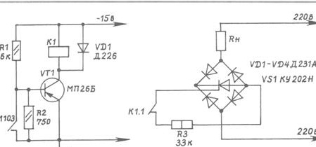
Work circuit. At a low temperature, the sensor contacts are open, voltage is applied to the base of transistor VT1, it is open, the relay is on. Its normally open contacts are closed, they close the thyristor control circuit, the thyristor is open, the heater circuit is on.
When the set temperature is reached, which is set by the adjusting screw on the sensor contacts, the contacts will close, the transistor will close, the relay will open the thyristor control circuit and the heater circuit will turn off.
The sensor must be disassembled, for this its faceted part is clamped in a vice and a thin brass glass is cut around the circumference to a shallow depth with a hacksaw for metal or a file. Remove the contacts from the glass. The long terminal of the movable contact is used to secure the contacts in the incubator. Solder wires to the contacts. Sensor adjustment is easy. When the adjusting screw is rotated clockwise with a thin-blade screwdriver, the temperature in the incubator decreases, while counter-clockwise rotation increases. Deformations of the moving contact should be avoided.
In the incubator, the contacts should be arranged so that there is convenient access to the adjusting screw and free movement of the movable contact.
As a drawback, it should be noted that, as experience has shown, after the chicks are hatched, fluff remains in the incubator, which, falling between the contacts, can disrupt the operation of the thermostat. Therefore, after hatching, it is necessary to carry out wet cleaning.
Such a scheme successfully worked for me for two seasons.It must be remembered that in both schemes the relay contacts, thyristor, bridge diodes are under voltage, therefore, when adjusting, you must follow the safety rules.
Before the first laying of eggs in the incubator, it is necessary to check the incubator for 1-2 days, controlling the temperature using a thermometer.