

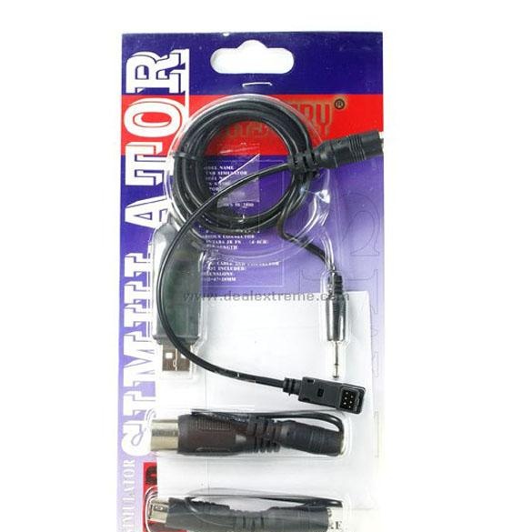
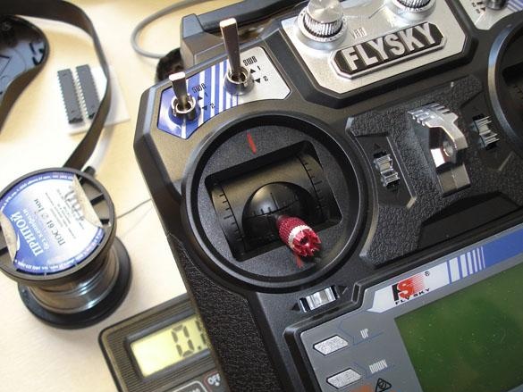
Almost all modern equipment for controlling radio models (such as Futaba, Hitec, Multiplex, FlySky, etc.) has a TRAINER connector on board, with a PPM output (analog coding principle), which is used to connect a transmitter (control panel) to the computer in the usual joystick mode, so you can virtually train in virtual model aircraft, helicopter, etc. without risking breaking the real model. To connect the remote control to the computer, special purchased adapter cables are used,
Type of such
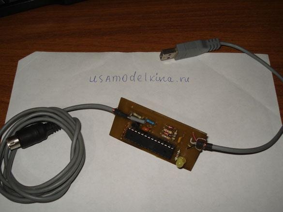
But we the inhabitants of our site we can make a home-made analogue of the adapter, one of the best circuit options is a USB cable on the atmega8 microcontroller, designed by Oleg Semenov, Vadim Kushnir, Vitaliy Puzrin. This self-made software can work with any number of channel pulses from the remote control (transmitter) and does not depend on their polarity, not all purchased adapters can do this.
Step 1. What we need.
•
• BC 547 (or KT315, KT3102)
• Two zener diodes for 3.3-3.6v. (e.g. 1N5226, 1N5527, KC133)
• Resistors 68 Ohm-2 pcs., 2.2k., 4.7k., 10k., 200k., Capacitor 0.22
• Ceramic or quartz crystal at 12 MHz
• USB extension cable 1m. or more (for parts), S-video cable (for parts)
• Soldering accessories, PCB board.
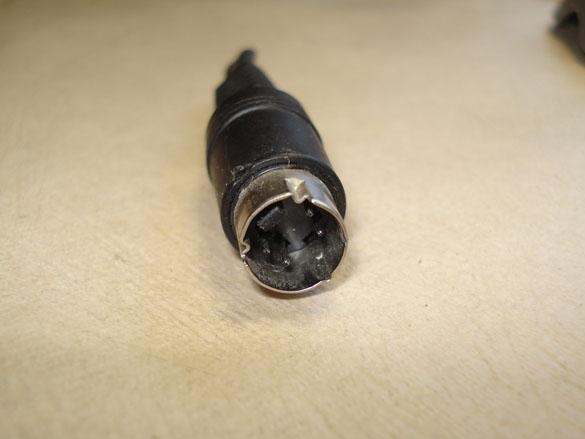
Step 2. Making a plug for the connector "TRAINER".
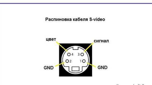
The plug for the S-video cable is ideal for the TRAINER connector.
Only it must first be properly soldered.
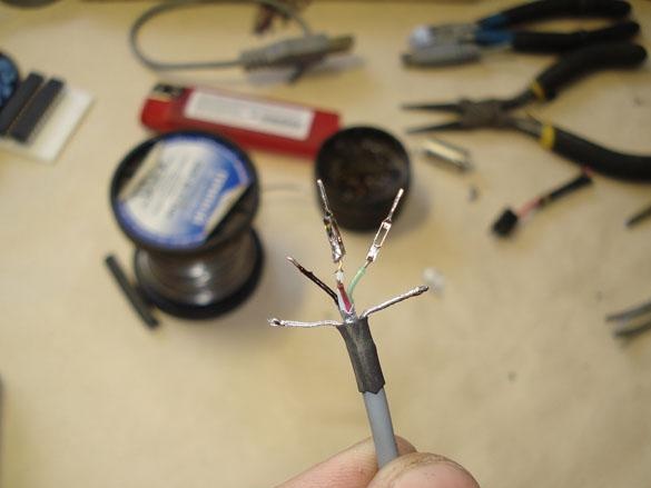
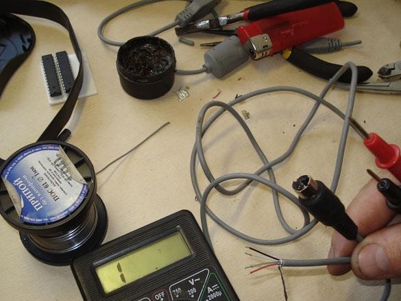
On the picture: This is the standard wiring of the S-video cable.
On the picture: And we need to redo it according to the following scheme below.
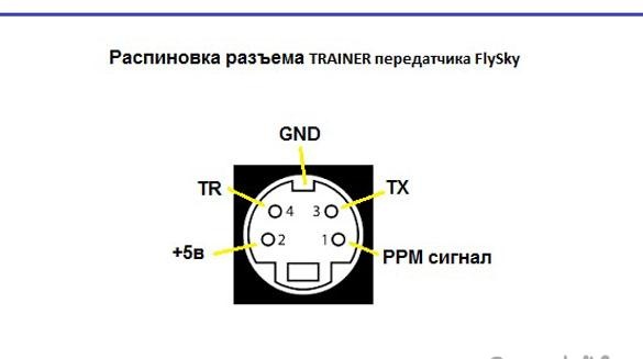
This option is suitable for FlySky remotes, for other manufacturers of remotes the pinout may be different, so first you need to look-check additionally on the Internet.
To work with the simulator, only 1pin will be used - PPM signal and GND.
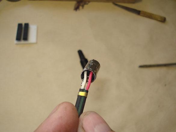
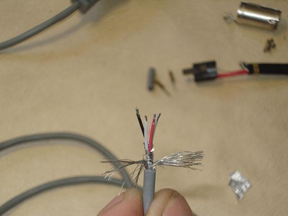
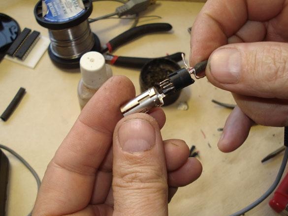
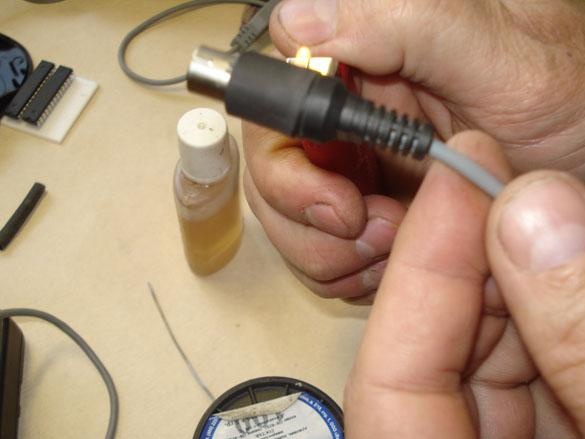
We take the s-video cable and cut off the plug we need.
We remove the plastic shell (case), if it is not removable, make a cut with a knife and remove.
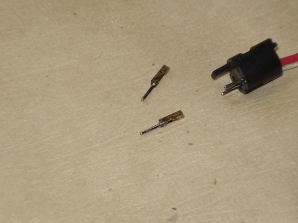
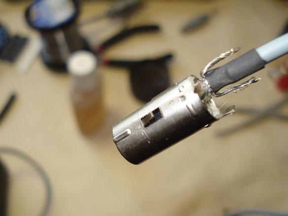
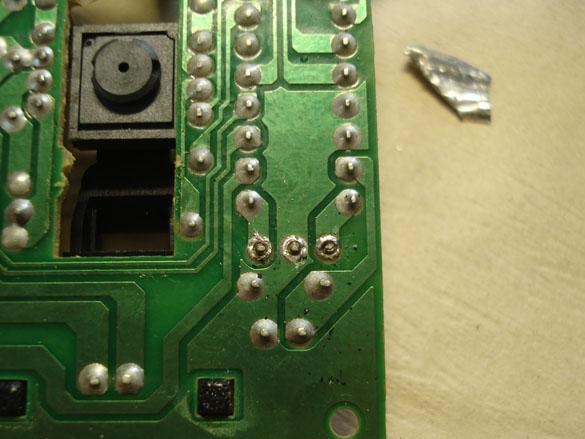
Inside, it is clear that the two input wires are soldered to the wrong pins for our circuit, and the other two pins are connected together to the body, which also does not suit us. Therefore, we take out all the insides.
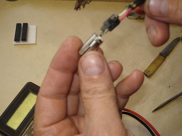
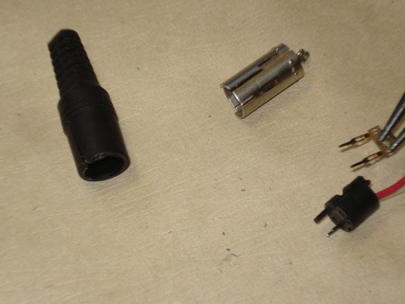
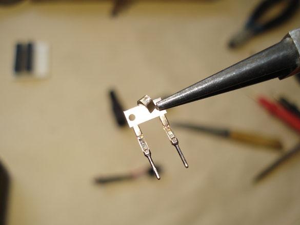
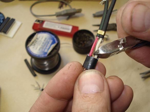
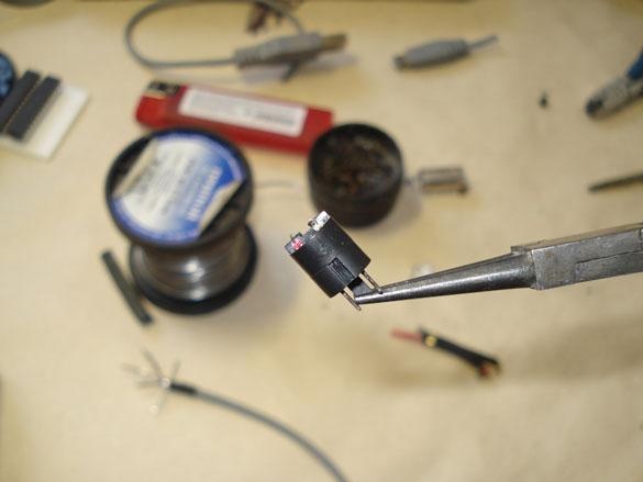
We take out the GND legs and disconnect them.
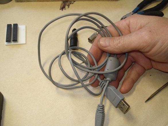
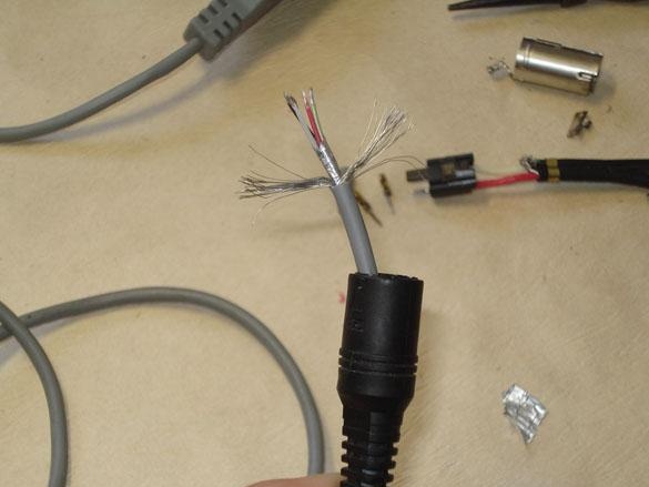
We take the prepared USB extension cable, cut off the Type A connector with a 20 cm piece of cable and set it aside for further connection to the board.
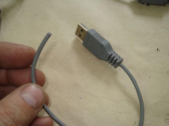
We take the rest of the cable, at least 80 cm long., Cut the ends to connect to the plug.
Immediately put the sheath on the cable.
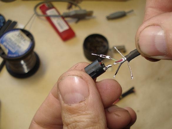
The stripped wires are ennobled with a piece of heat shrink.
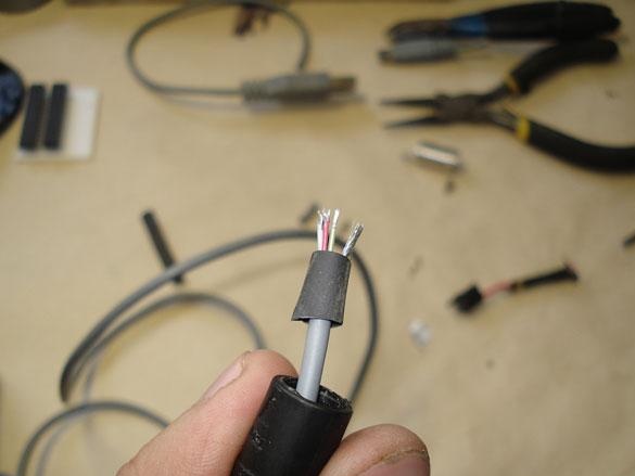
We serve the ends of the wires.
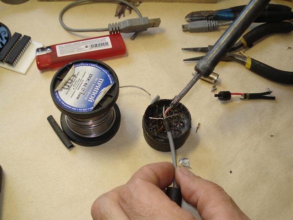
Solder the legs of the connector and insert them into place in accordance with the connection diagram to the remote control.
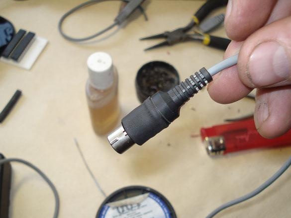
We assemble the connector, fix everything to hot-melt adhesive and put the shell of the case in place.
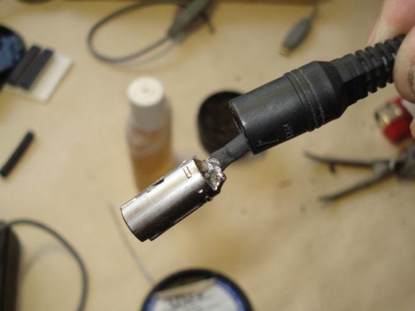
To repair the cut case, we put on several heat shrink tubes and crimp with heating.
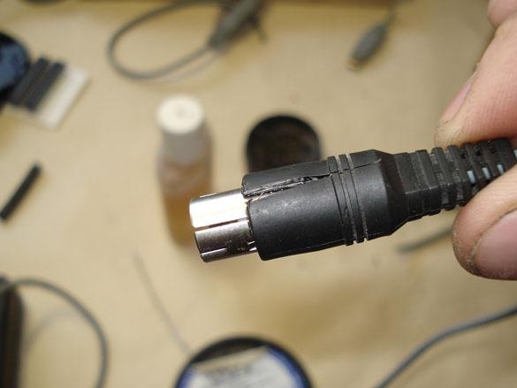
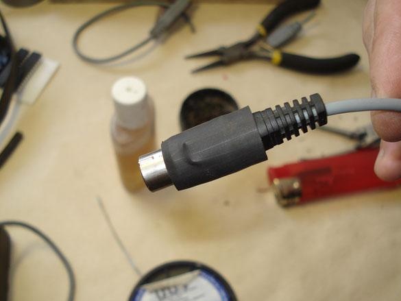
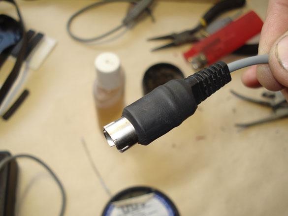
We check the operability of the cable received by the tester, if the circuit rings, there is no short circuit, then the cable is ready.
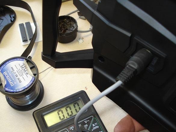
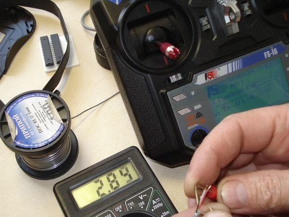
Now you need to insert the plug with the cable into the TRAINER connector, turn on the remote control (transmitter) and measure the presence of voltage at the output of the PPM signal wire, it should be about 3 volts, if this is not, you need to check the voltage directly at the output of the console itself and configure the output in the menu.
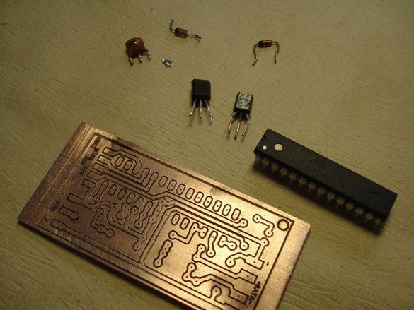
Step 3. Manufacturing the adapter board.
The main circuit of the adapter.
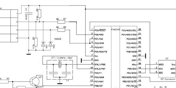
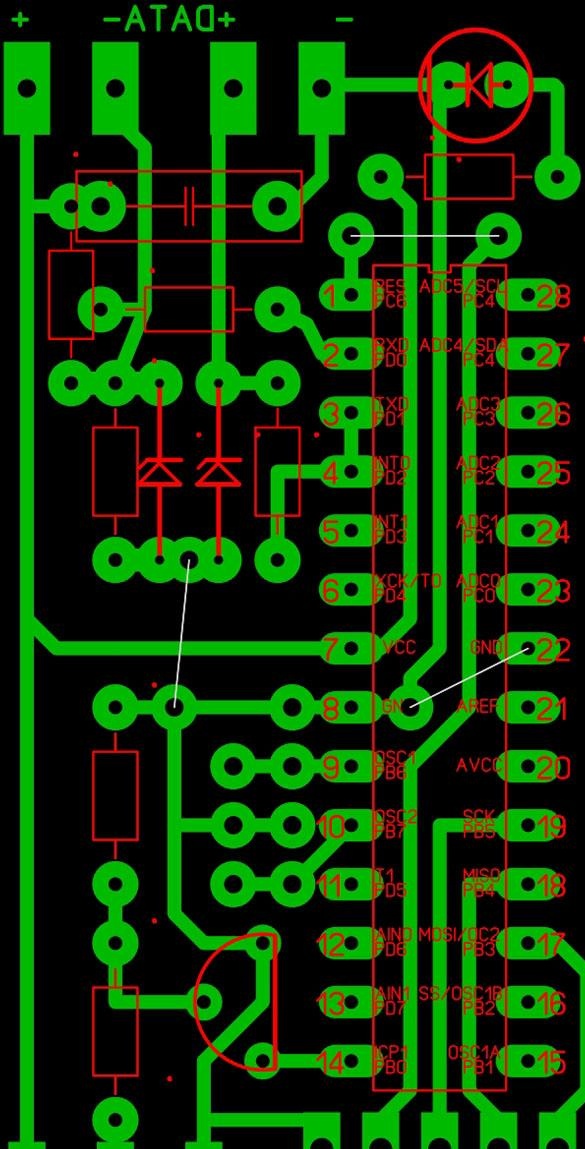
According to this concept, we design a circuit board.
I got such a small board, it was made in the program Sprint-Layout.
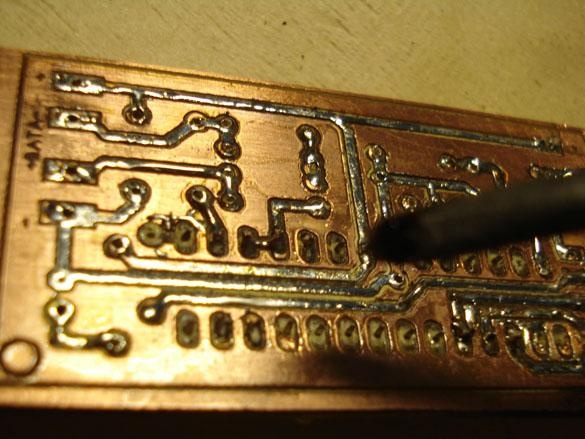
We make the board itself in one of the ways available to you, LUT, CNC, etc.
I have fun on the CNC.
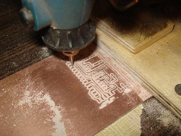
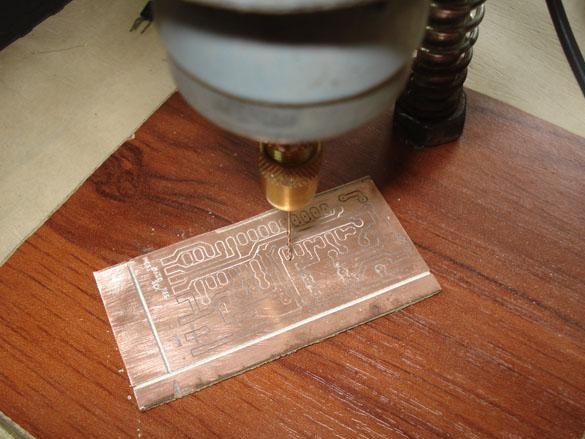
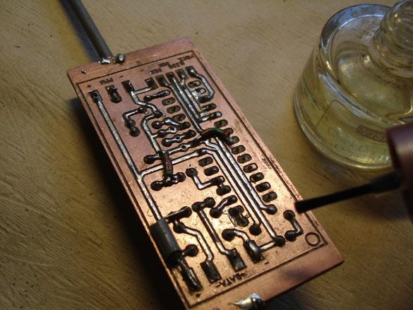
The result was such a scarf.
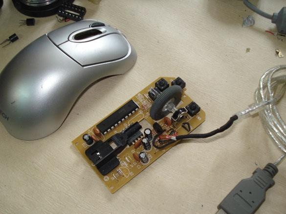
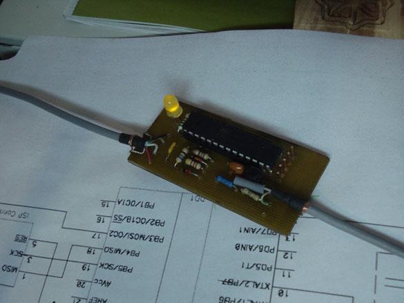
Step 4. Wiring the board.
Do not rush to immediately buy quartz at 12 MHz, each house has an unnecessary usb computer mouse, an old flash drive or other unnecessary USB devices, check them inside, for sure there is what you need.
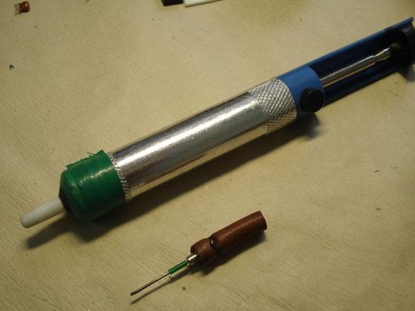
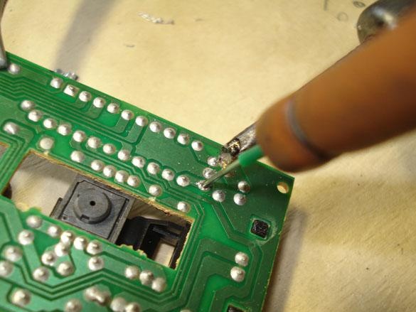
The suction failed, so I used the old grandfather method, the needle from the Spitz.
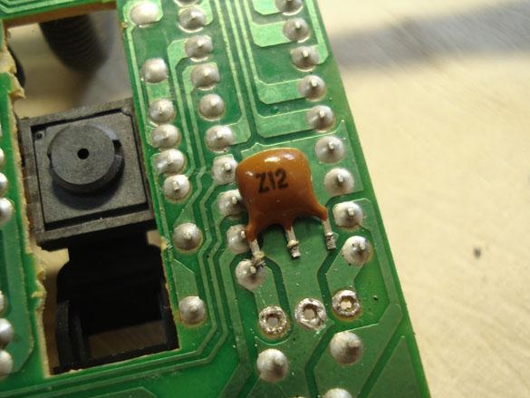
We solder all the details onto the board, solder our manufactured cable with an s-video plug and 20 cm previously prepared. USB cable.
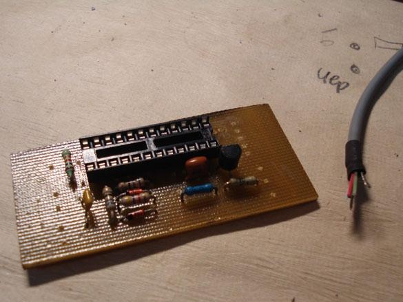
We cover the finished board with varnish.
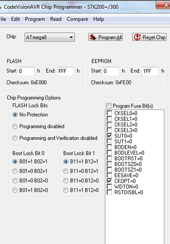
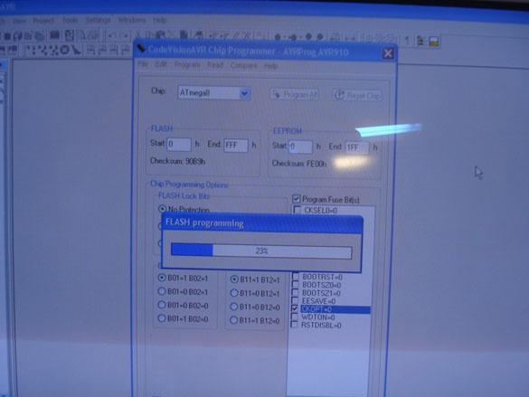
Step 5. Firmware microcontroller.
For firmware via the CodeVisionAVR program, we expose the fuses as in the photo below, for PonyProg, vice versa, respectively.
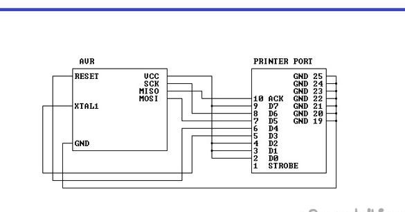
We flash MK through the programmer or simply through the LPT port according to the scheme below.
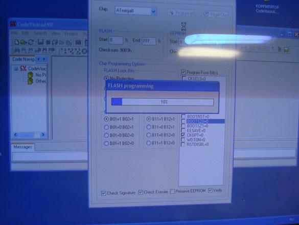
Firmware process.
Step 6. Checking the finished device.
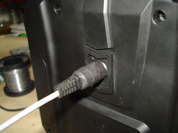
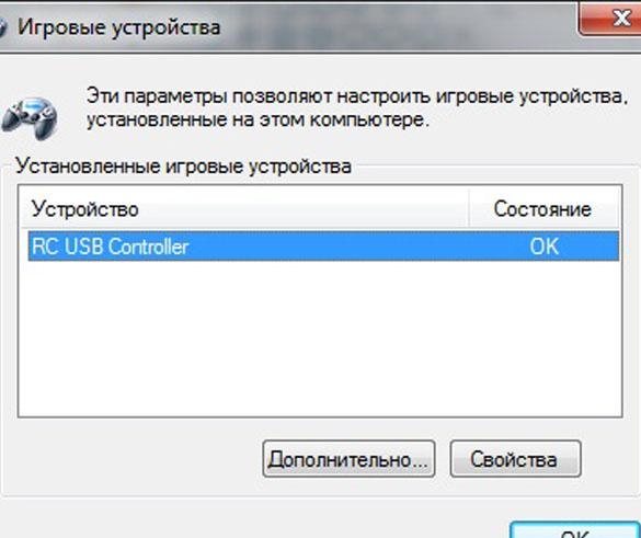
We connect the finished device to the USB port of the computer, it should be defined as a gaming device (joystick), if you have an Internet connection, it will probably happen before the installation of the device driver.
After the notification appears that the device is ready for use, you can go to the START DEVICES AND PRINTERS, there we will see the image of the joystick.
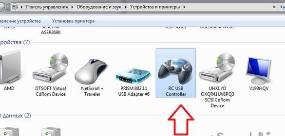
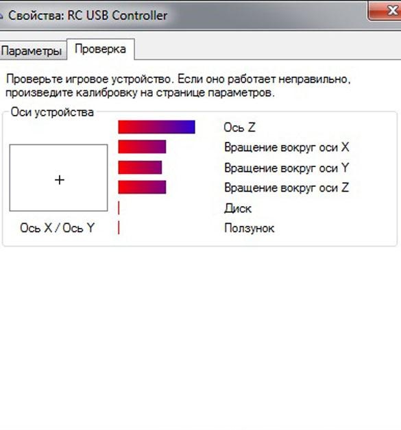
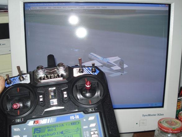
We go into the properties and check the operation of the axes, if everything works, it remains to run one of the many simulator programs, configure, assign the axes and you can fly!
If the adapter is not detected by the computer, then you need to check the wiring diagram.
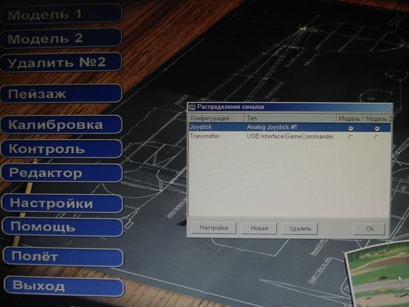
AeroFly Professional Deluxe Simulator Example
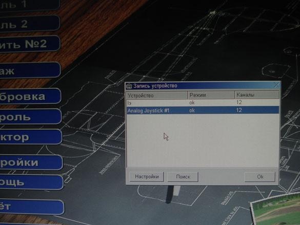
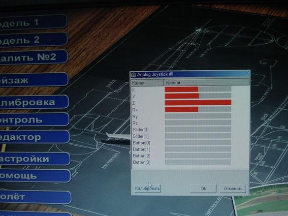
We select our joystick.
We calibrate the axis.
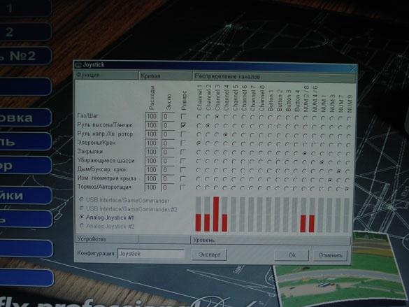
Set the axis to the desired channels.
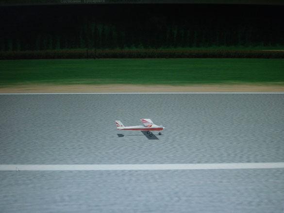
Hurray, flew!

Firmware, scheme, etc.