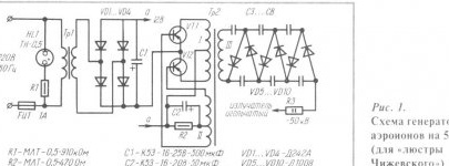
In the general case, the aeroion generator consists of a power source, a high voltage unit and a radiator. In fig. 1 shows a diagram of a generator of negative aeroions similar to that proposed by the famous scientist A.L. Chizhevsky in 1931. High voltage generator unit is a circuit for converting and multiplying the voltage of a power source to a voltage of 50 kV. The power source includes a transformer Tr1, a bridge rectifier, as well as a capacitor C1 with an output voltage of 12 V. The core of the transformer Tr1 of the source is assembled from plates of the SZO type (set thickness 20 mm). The primary winding of the transformer contains 1500 turns of wire PEV-0.4, the secondary winding contains 90 turns of wire PEV-0.9. Instead, any other power supply with a permissible load current of at least 1.5 A is suitable.
To enlarge the image, click on it.
The windings of the transformer Tr2 of the high-voltage block are wound on the core from the line transformer of the TV (type TVS-110). The winding I consists of 14 turns of wire PEV-0.8 (tap from the middle); winding II - from 6 turns PEV-0.8 (tap from the middle); winding III - from 8000 turns of PEL-SHO-0.8 (or from 10000 turns of PELSHO-0.1). In winding III, after every 800 turns, an insulating strip of fluoroplastic with a thickness of 0.1 mm (from FT type capacitors) is laid on the wires. It is allowed to use condenser paper 0.2 ... 0.3 mm thick wound in 2 ... 3 layers. The same spacers must be separated from each other windings I and II, as well as II and III.
Details Transistors VT1 and VT2 (KT837A) indicated in the circuit can be replaced with P217 transistors with any letter, GT806 B ... D, KT837 with any other letter. Instead of rectifier posts VD5 ... VD10, KTs105D, KD201D, D1007 are suitable. High voltage capacitors are any rated for a voltage of at least 10 kV.
Generator elements are placed on a mounting plate made of getinax or textolite with a thickness of 2 mm, the installation of radio elements is mounted. The case of the generator block is made of aluminum 1 ... 2 mm thick, U-shaped radiators for transistors are made of the same material. The assembled unit is placed near the place of suspension of the emitter so that the 50-kilowatt output is as short as possible. For output, they take a high-voltage wire of an automobile ignition system or a television cable RK-75 with a removed wire braid.
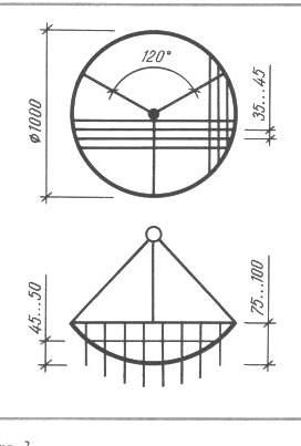
Emitter - a screen, which is a copper ring, to which a grid of copper wire is soldered with a diameter of 0.3 ... 0.5 mm (the diameter of the wire ring is 2 mm). The insulation from the wires, of course, is removed. The grid has square cells, the convex part of the screen is directed downward (Fig. 2). Sharpened pieces of copper wire with a diameter of 0.25 ... 0.5 mm and a length of 45 ... 50 mm were soldered into the corners of the cells. Suspensions are attached to the ring - 3 copper wires with a diameter of 1 ... 2 mm, deployed at an angle of 120 ° and soldered above the center of the emitter. The emitter is suspended from the ceiling using a ring made of dielectric material. The wire from the high-voltage block is connected to the suspension wires or to the ring. To control the performance of the "Chizhevsky chandelier", a ribbon of tissue paper 10x80 mm in size, doubled, is suspended from the wire of the radiator grid. During normal operation, the lower ends of the ribbon diverge by 30 ° or more.

A treatment session with negative aeroions is carried out in a well-ventilated and clean room at a temperature of 18 ... 25 ° C and normal humidity. The first procedure lasts 10 minutes, then, increasing the procedure time by 2 ... 3 minutes daily, the duration of the procedure is adjusted to 30 minutes. The procedures are carried out daily, the course of treatment is 20 ... 25 procedures. As a rule, they return to the second course after 6 ... 8 weeks. For the prevention of diseases, the "Chizhevsky chandelier" is switched on every other day for 5 ... 10 minutes.
Treatment with the Chizhevsky chandelier is recommended for mild to moderate bronchial asthma; with sinusitis, rhinitis, pharyngitis, laryngitis, bronchitis, burns, wounds, trophic ulcers, neurosis; also with increased fatigue, insomnia, headache.
Contraindications: severe forms of bronchial asthma, pulmonary emphysema, chronic coronary heart disease with decompensation, severe cerebral atherosclerosis, active pulmonary tuberculosis, a sharp general depletion of the body.
This design of the generator of aeroions has the following disadvantages: high complexity in the manufacture, as well as the need for periodic shutdown. A much more attractive design for independent manufacture is the design of the generator, where nickel or nichrome wire with a diameter of 0.1 ... 0.3 mm is used as ionizing electrodes. The use of wire as electrodes makes it possible to obtain a more uniform distribution of aero ions in the room than with needle electrodes. A very important advantage of wire electrodes is that during their operation, ozone and nitrogen oxides are not released. At the same time, generators with such electrodes can work for a long time without causing an overdose.
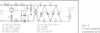
A diagram of the aeroion generator generating a constant negative voltage of 20 kV to power wire electrodes is shown in Fig. 3. In this design, the frequency of the supply voltage of 50 Hz is increased to 1000 Hz by the VS1 single-converter converter. The shunting of the dynistor by the VD1 diode is used to reduce the magnetization current of the magnetic circuit, which leads to an increase in the voltage at the transformer output. Thus, the mains voltage is increased using a transformer and a voltage multiplier, and then through the limiting resistor R4 is supplied to the wire electrodes.
To enlarge the image, click on it.
Details The circuit used resistors type MLT; capacitor C1 of the MBM brand, designed for a voltage of at least 500 V (it can be replaced with capacitors of the MBG type; MBGO; K42-11; K42U-2). Capacitors C2 ... C5 are polystyrene type POV, but with a voltage of 10 kV (they can be replaced with capacitors of the KBG, K73-12 type). Instead of the VD1 diode, it is not forbidden to put any other diode with a pulse reverse voltage of at least 800 V, for example, KD209B or MD217. A high-voltage transformer is used ready-made, type TVS-90PZ. In the absence of fuel assemblies, a high-voltage transformer is wound on a tube made of electric cardboard with an external diameter of 8 mm and a length of 150 mm, inside which a rod of ferromagnetic material is placed (the size of the tube). Primary winding the transformer contains 60 turns of wire PEV-0.3, it is wound directly on the frame. Then the winding is insulated (wrapped) with 2 ... 3 layers of capacitor paper or a layer of fluoroplastic tape. Secondary winding contains 5 thousand turns of PELSHO-0.12 wire, wound round to round (winding length 70 mm). Each layer of the secondary winding wire is separated from the subsequent one by one turn of fluoroplastic tape or two turns of capacitor paper. The finished transformer is impregnated with paraffin (bakelite varnish is allowed, as well as glue BF-2 or BF-4). It is better to choose a ready-made multiplier for a voltage of 18 ... 22 kV.
As a material for a wire electrode, a wire of nichrome, nickel, constantan or another alloy with a high resistivity is suitable. The electrode wires are placed around the perimeter of the room. A single electrode can be tensioned diagonally or in the middle of the ceiling, but in this case, the generator efficiency decreases by about a third.
When hanging a wire electrode in a room, certain requirements must be observed. So, the distance of the wire from the walls should be more than 300 mm; from the ceiling - more than 500 mm; between wires - more than 2500 mm. The height of the wires from the floor is 2500 m. If these requirements are violated, the number of generated ions decreases and the uniformity of their distribution in the room deteriorates.
The wires are fastened in the corners using a piece of fishing line with a metal washer at the end (Fig. 4). Thus, the wires screwed to one washer cannot but close, that is, form a single circuit. The free end of each fishing line is attached to the wall. For standard living rooms, four stretch marks are usually enough. On the wire electrode, the formation of nodules is undesirable; slight sagging does not affect generator efficiency.

Installation of a high-voltage rectifier is carried out on a PCB or getinaks board with a thickness of 2 mm; the rectifier case is cut out of sheet metal 1 ... 1.5 mm thick. Rectifier
suspended on the wall at the same height as the wire. The limiting resistor and wire electrode are connected by a piece of high-voltage wire 150 ... 250 mm long (the high-voltage and electrode wires are connected by winding several turns of PEV-0.2 copper wire with remote insulation on them).
The concentration of negative ions in the breathing zone of this generator reaches 800,000 ions / cm3. To control the operation of the generator, a ribbon of tissue paper is attached to the electrode wire (as in the case of the Chizhevsky chandelier).
The generator of negative aero ions is even easier to manufacture, the circuit of which is shown in Fig. 5. Its assembly is similar to the generator shown in Fig. 3, with the only difference being that the number of turns in the secondary winding of the transformer with its independent manufacture is 2000 turns. The ion concentration of this generator is 300,000 ions / cm3.
In rooms where negative air ion generators operate, smoking and cleaning with a vacuum cleaner is not recommended. At this time, the generator must be turned off. They turn it on only after airing. The device is safe to operate, since the current in the electrodes is several tens of microamps, so that touching the electrode causes only a sensation of a pin pin.
Once a month (when the power is off!) It is recommended to wipe the wire electrodes and the device body.
Very interesting data on the use of the aeroion generator in greenhouses was received by the American scientist M. Frents. The wire electrode was suspended under the ceiling of the greenhouse, a steel plate 20x20 mm was placed in the bed, to which the device case was connected. According to the researcher, the yield of tomatoes and cucumbers when using the generator increased by 40 ... 60%.It should be noted that to repeat this experiment, it is necessary to reliably protect the generator elements from moisture. This can be done by filling its body with sealant or epoxy. All compounds are carefully soldered before pouring.
Literature:
Genkin V.I., Mityushin Yu.B. Electronics in agriculture. - M .: Knowledge, 1981.
Livshits M.N. Aeronification: practical application. - M .: Stroyizdat, 1990.
Clerk B.C. Home physiotherapy. - Minsk, 1993.


