

Today I will tell you how to make a radio button do it yourself. I did not check the range, but it catches confidently throughout the apartment.
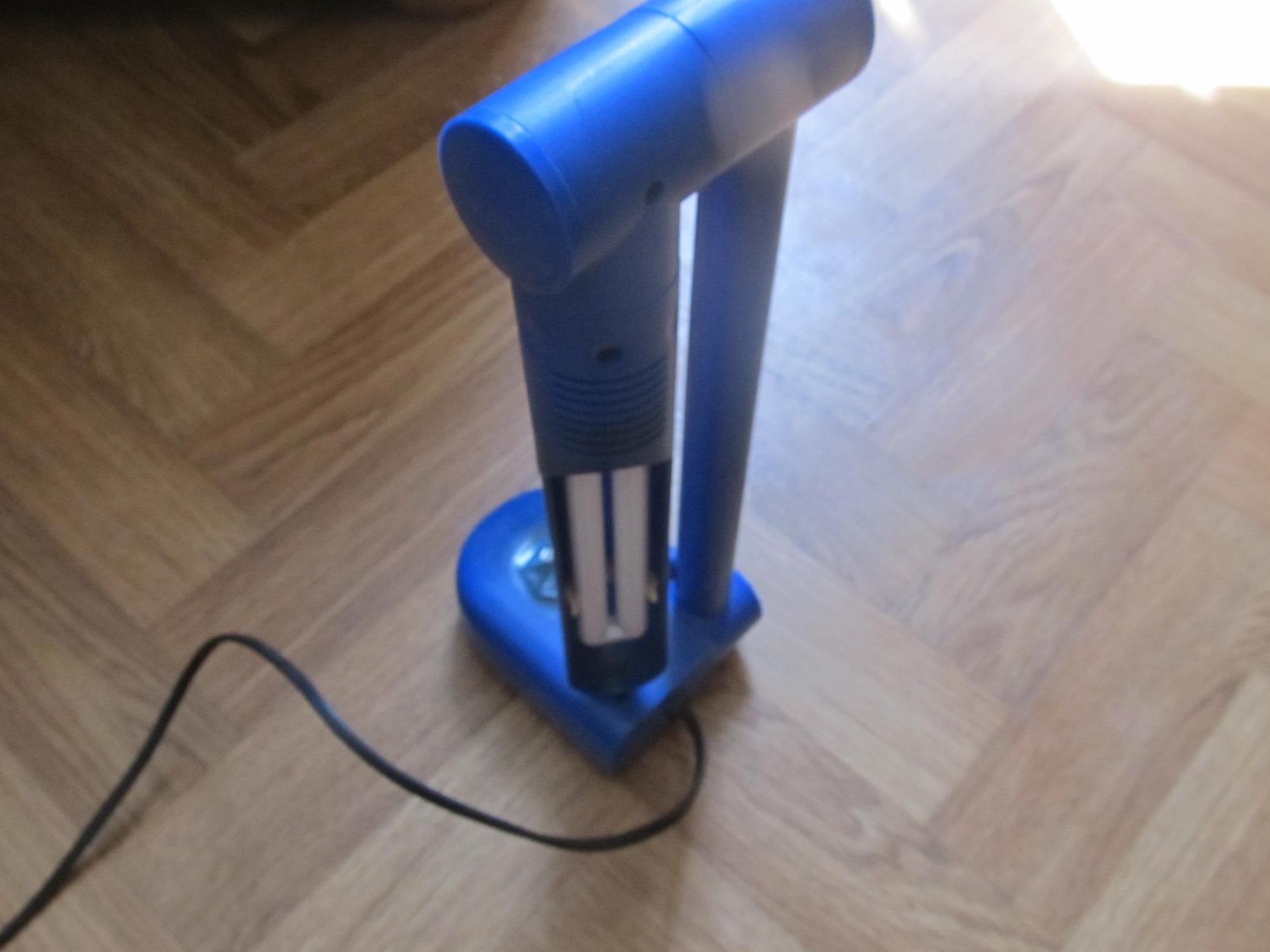
Using it, you can manage various loads. In my case, I chose a table lamp for the experiment.
For work, we need:
1) Soldering iron
2) Light
3) some radio parts
4)
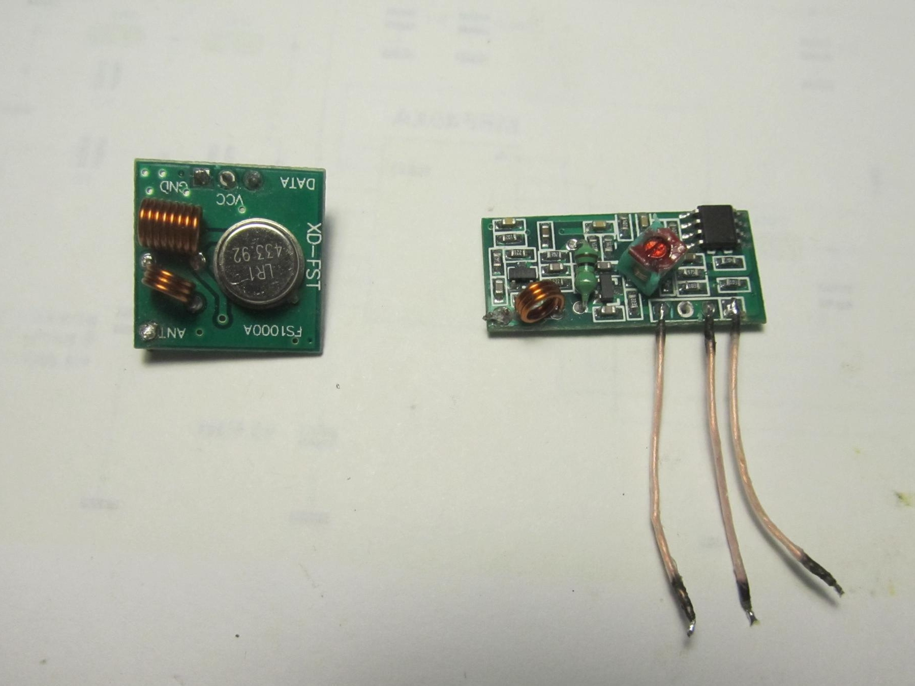
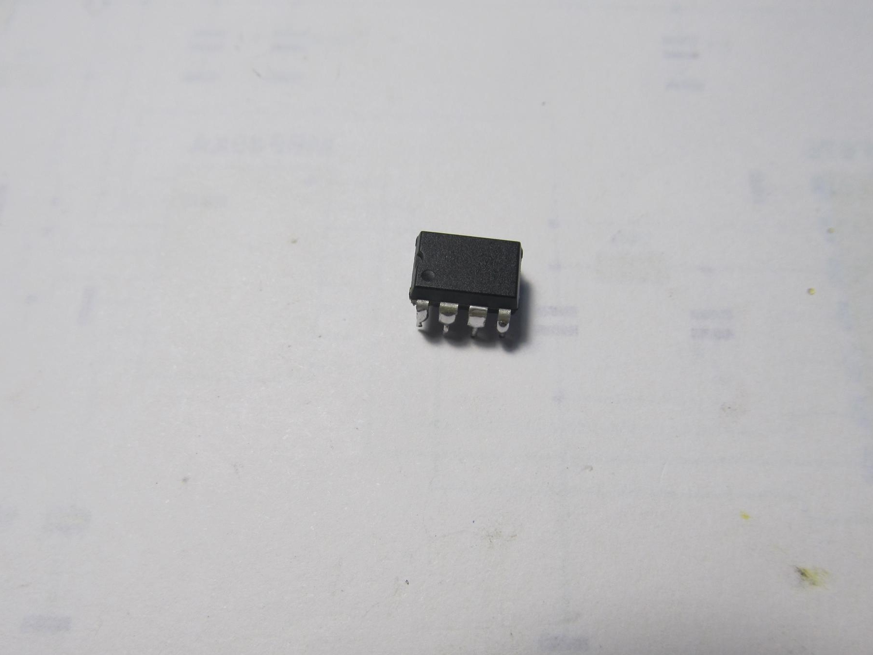
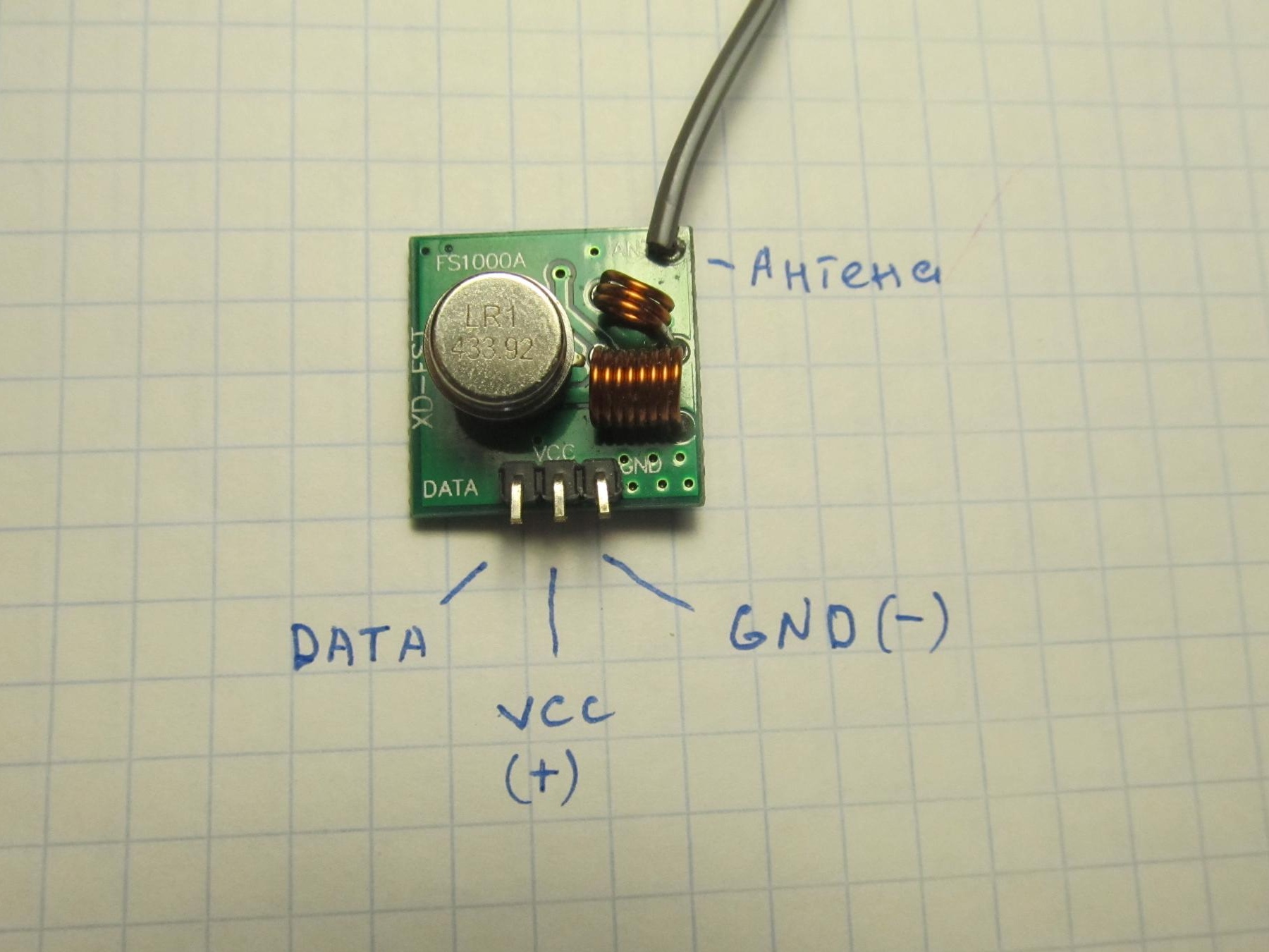
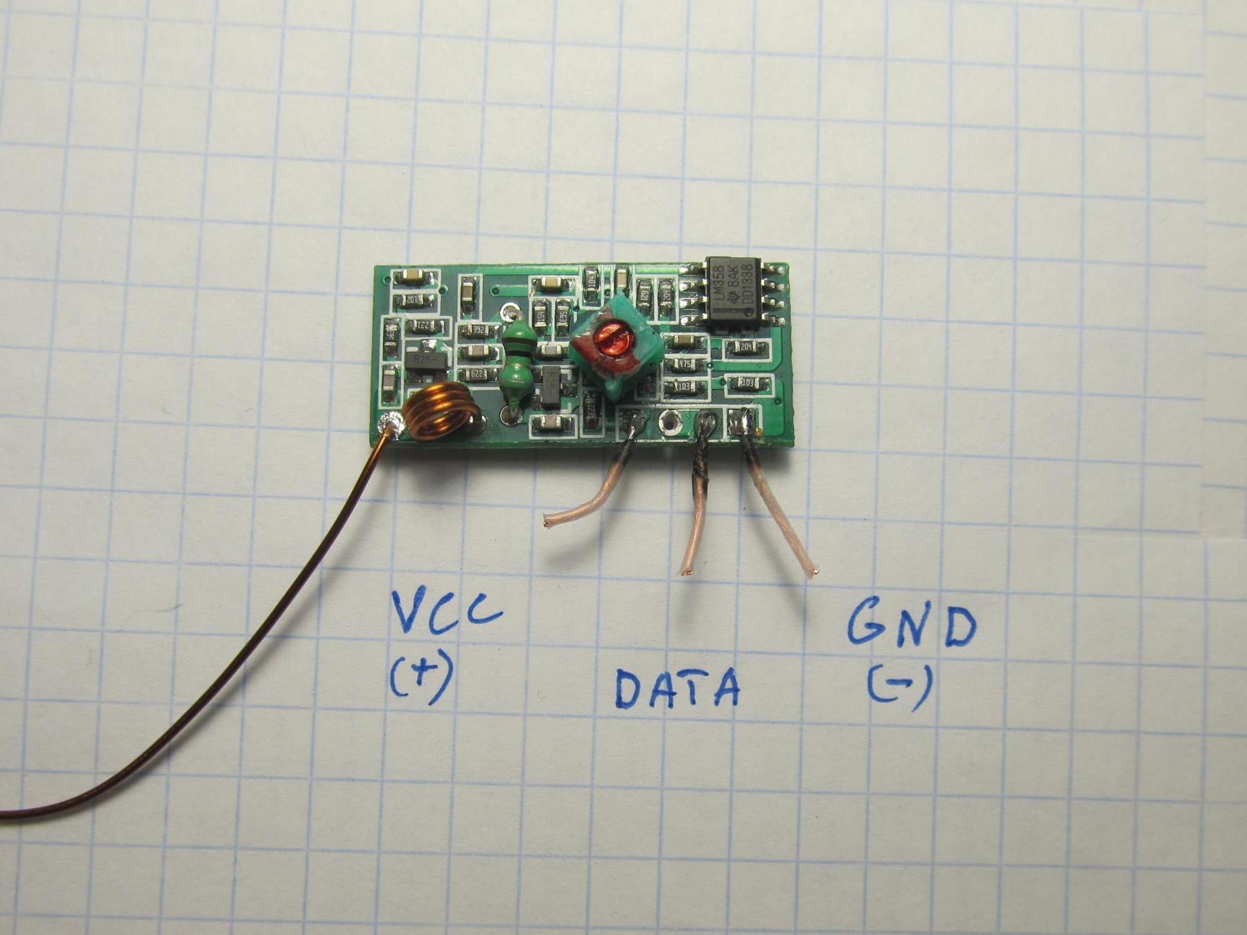
To transmit the signal of the radio button, cheap and common RF modules are used: receiver and transmitter, photo below
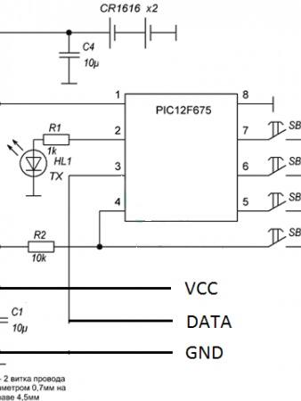
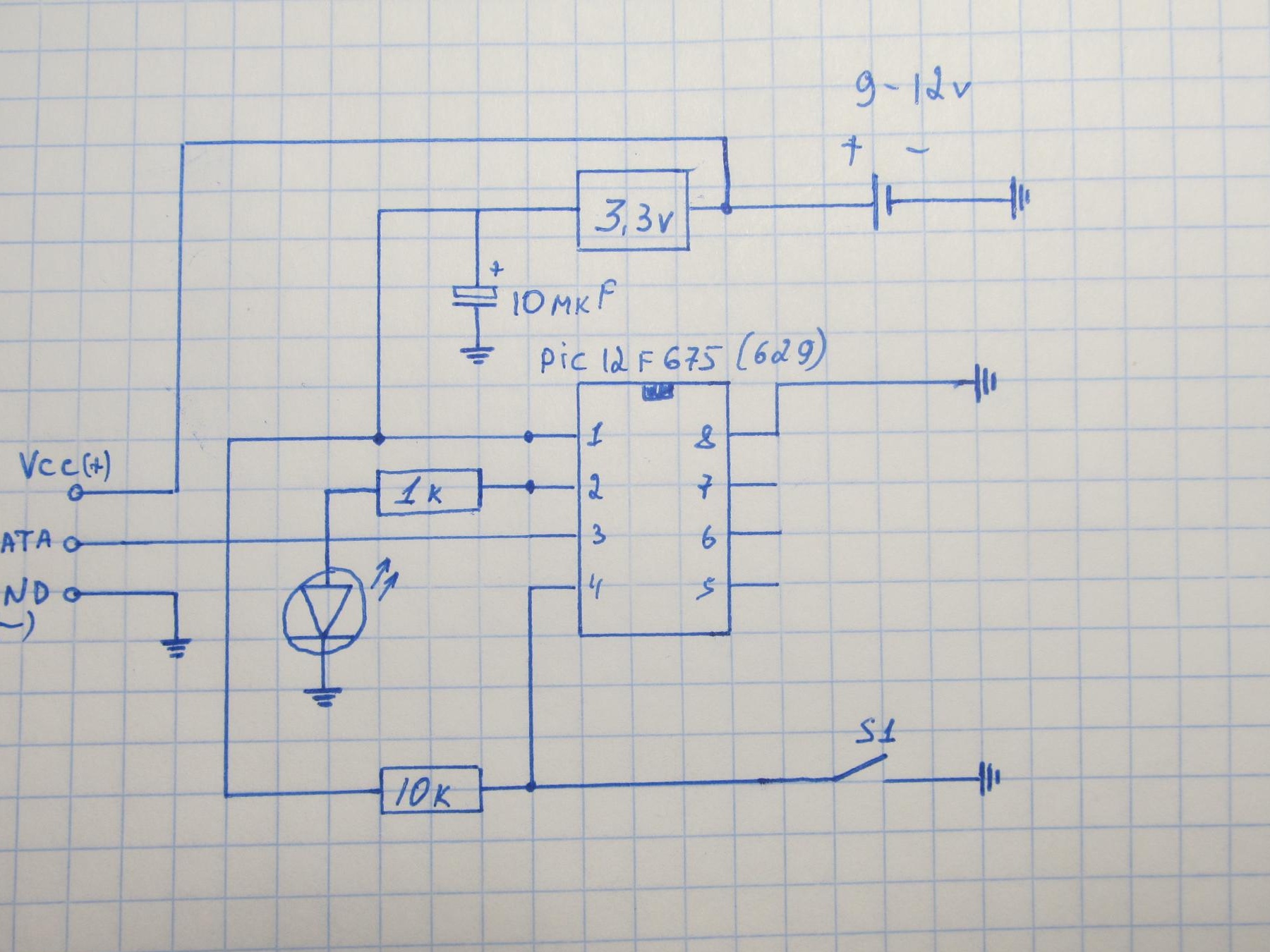
As a basis, I took this diagram:
TRANSMITTER
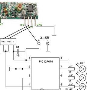
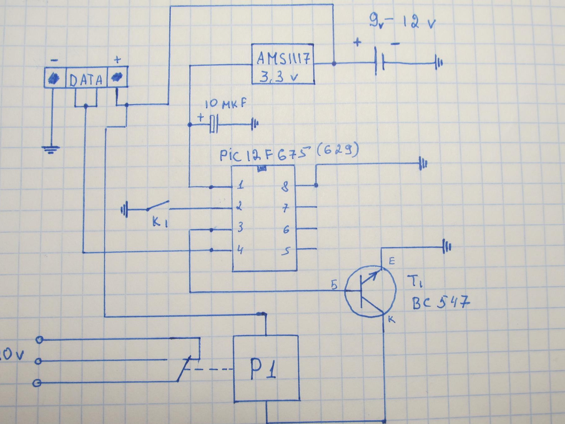
RECEIVER
The radio button is built on the common PIC12F675 or (629) microcontrollers.
For the button to work, these microcontrollers will need to be flashed. Firmware files are laid out at the end of the article.
The transmitter and receiver circuits were slightly modified. Since these circuits are designed to control 4 teams. But I as a trial version, I used only one command. The rest just did not connect.
Transmitter.
Receiver.
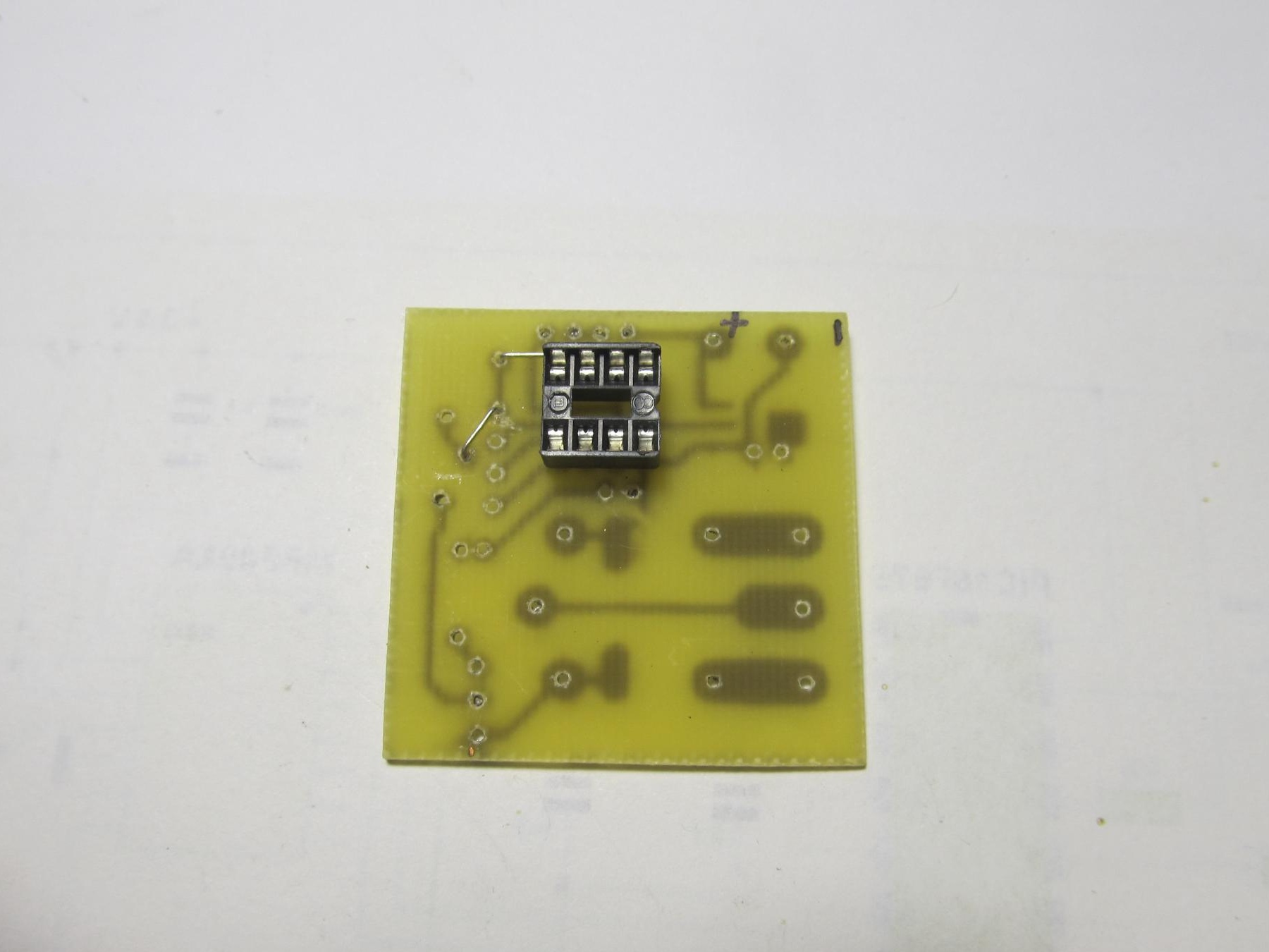
Further, according to the scheme, we make boards. Unfortunately, the board files were not saved, so there is no way to upload it.
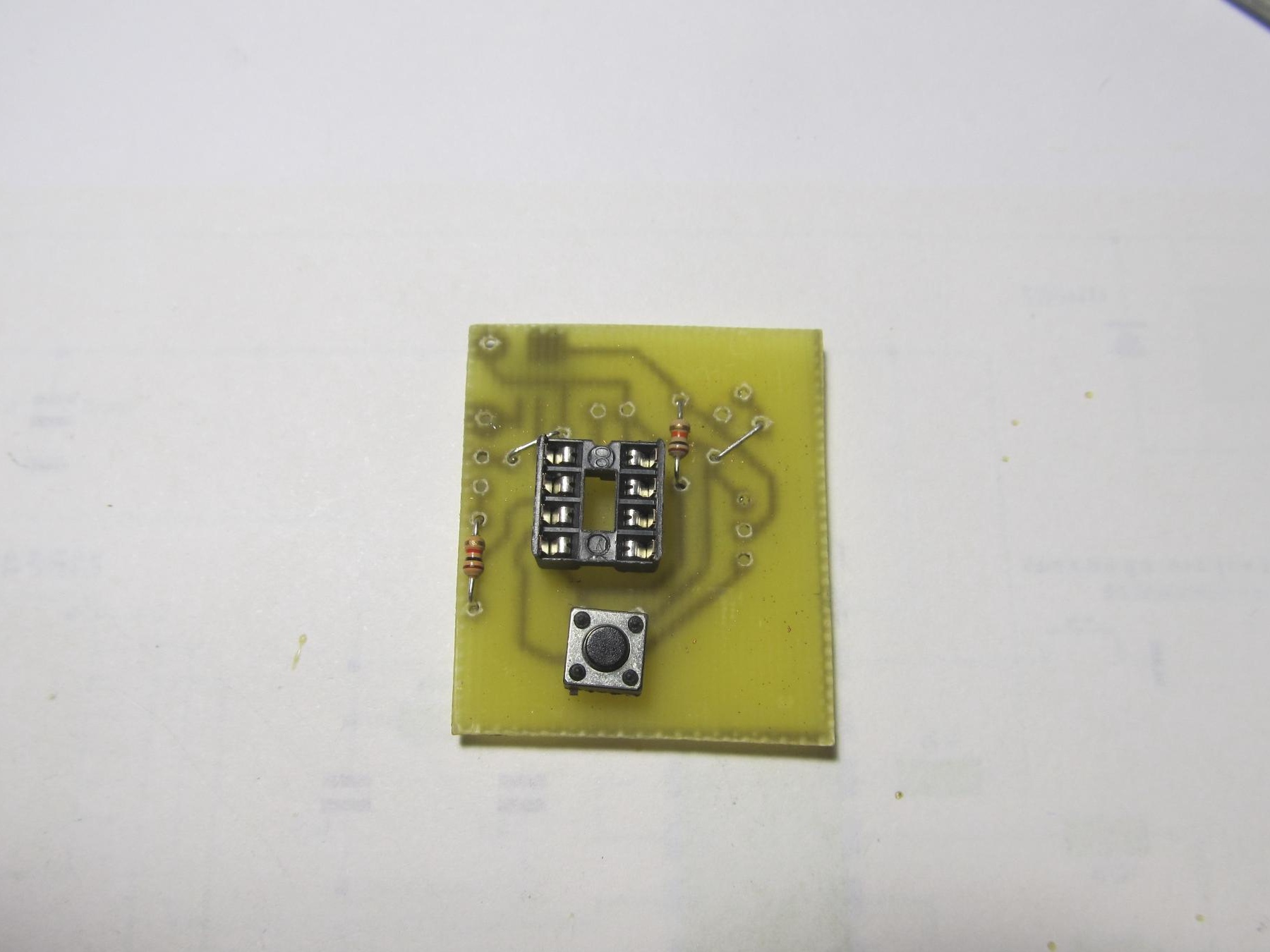
Whatever you are tormented with, how to connect RF modules, here is their pinout.
TRANSMITTER.
RECEIVER.
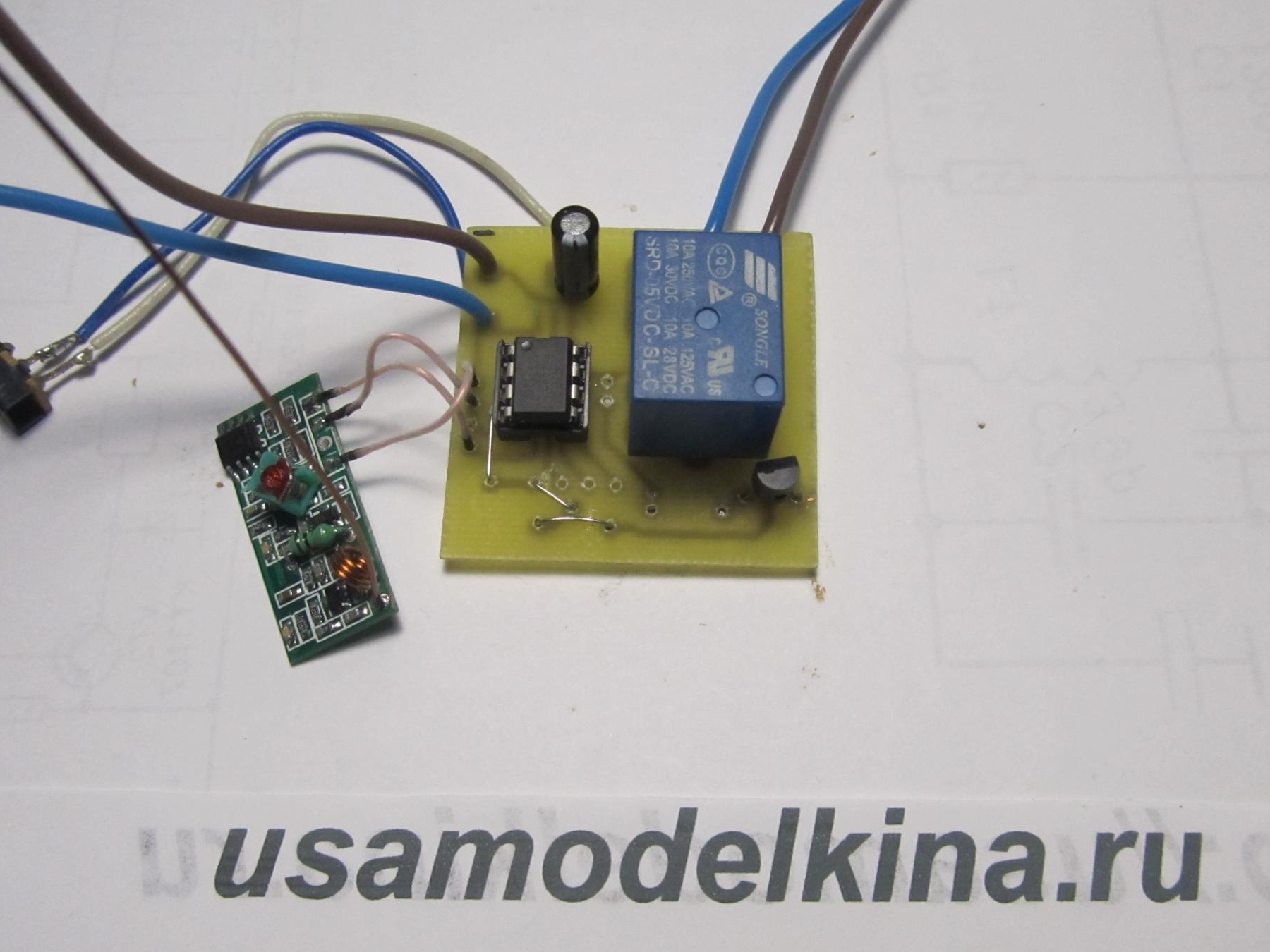
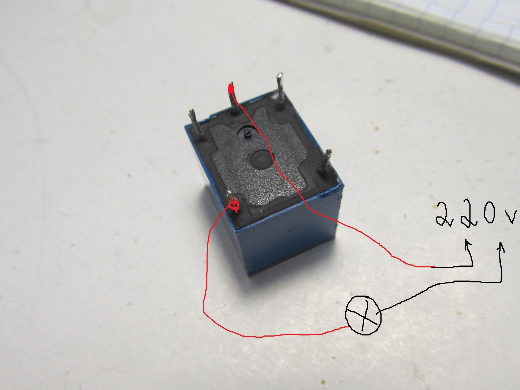
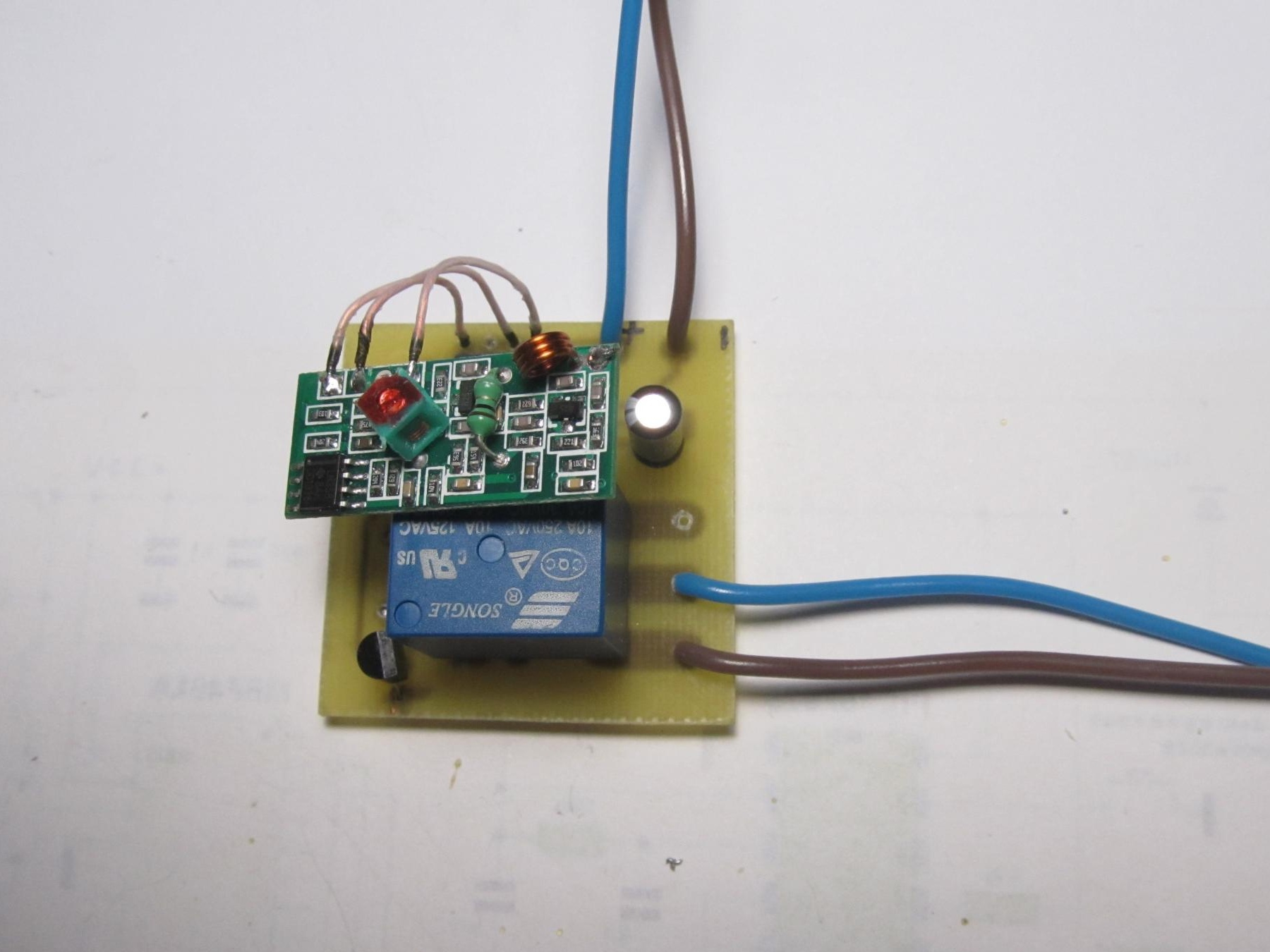
I found such a relay on the Internet, it will switch the lamp on and off.
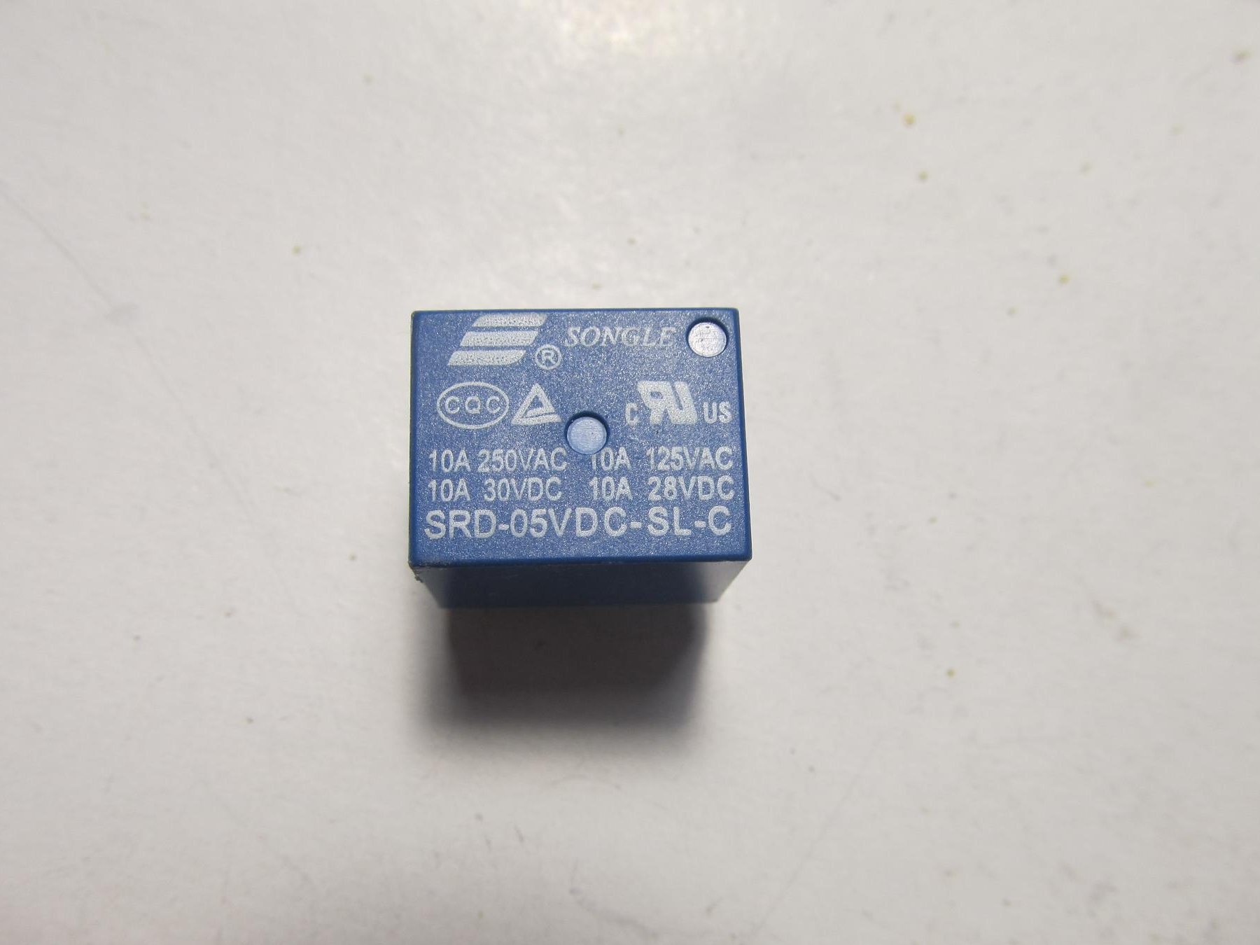
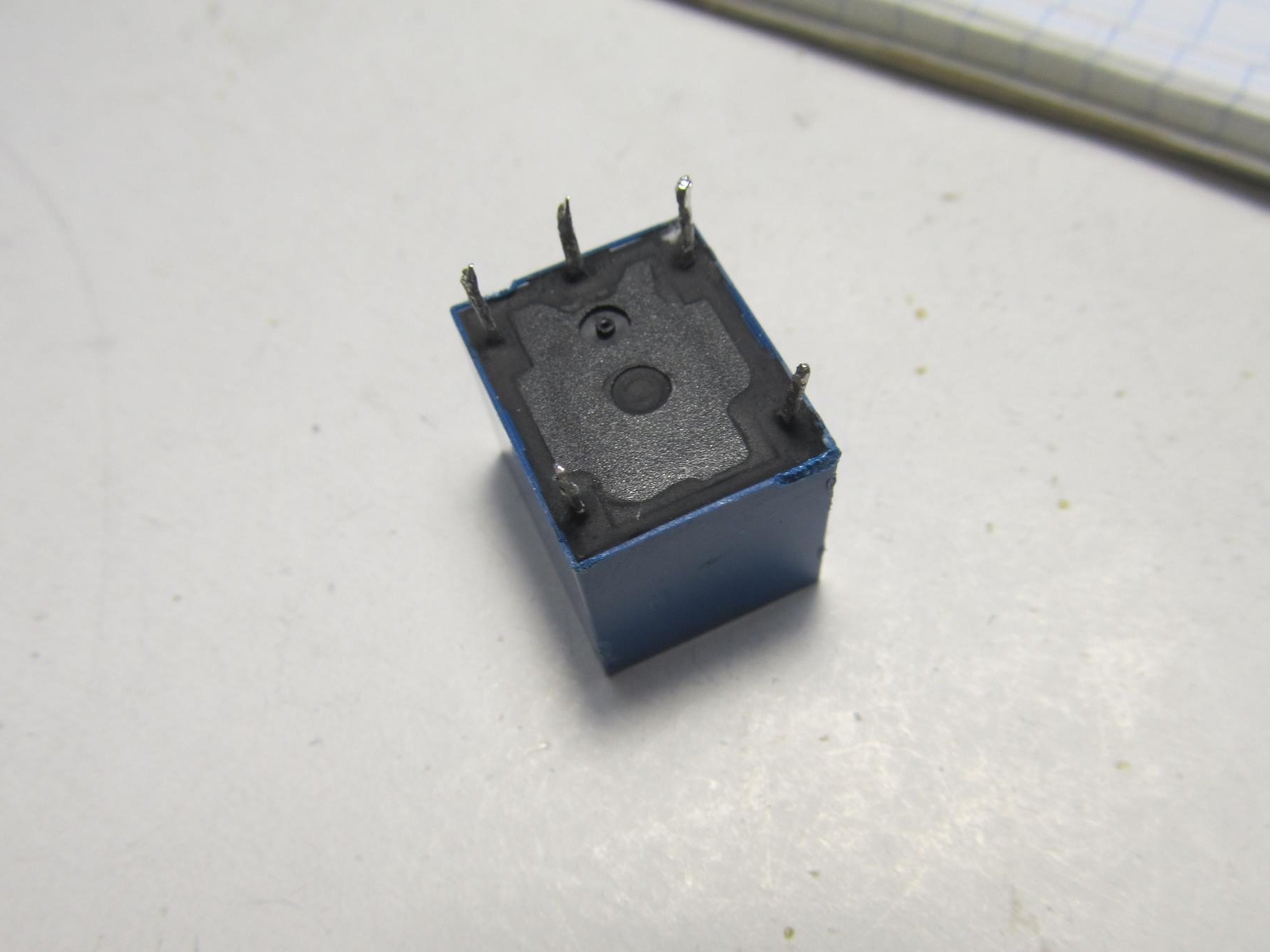
When connecting a relay, be very careful and attentive, ring the relay before connecting or ask those who know. For example, on my relay, on the one hand there are 3 outputs, and on the other 2. So where there are 3 outputs, the signal from the transmitter is fed to the 2 extreme ones, and the load is connected to the middle and 2 from the other side.
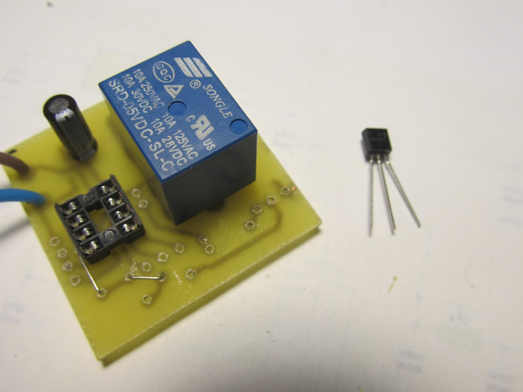
Next, solder everything into place.
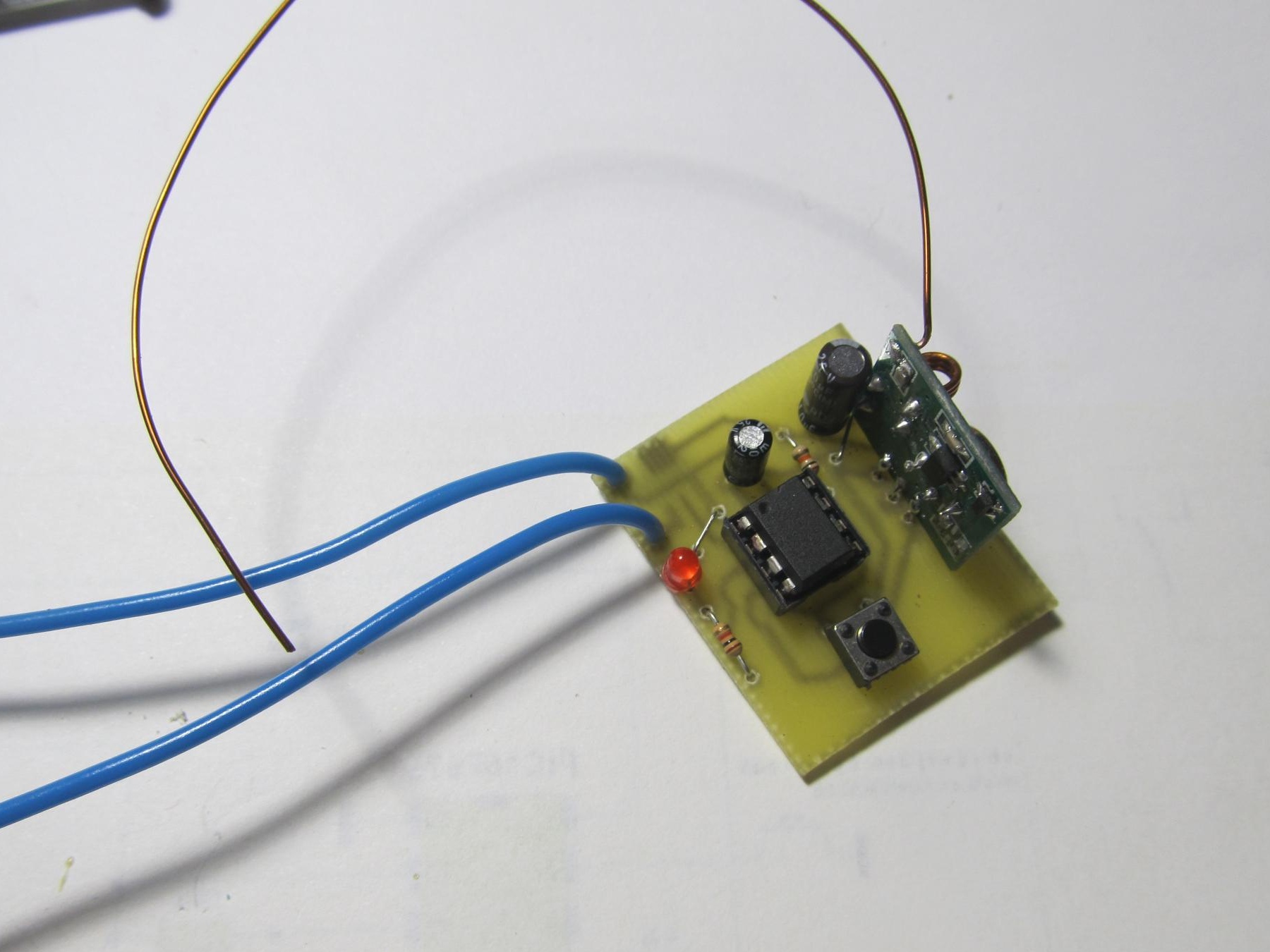
Then I took the lamp.
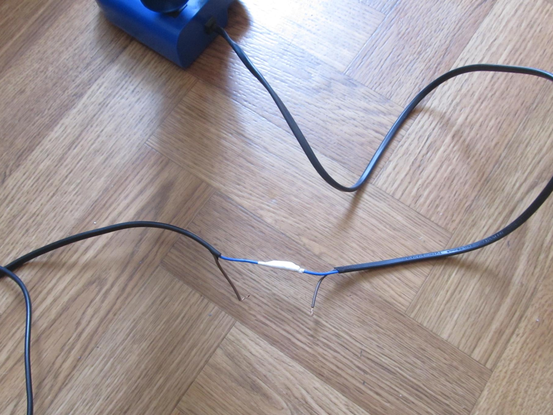
I made two conclusions in the wire. It is these conclusions that will be connected to the relay. Just connect everything before plugging the lamp into a socket.
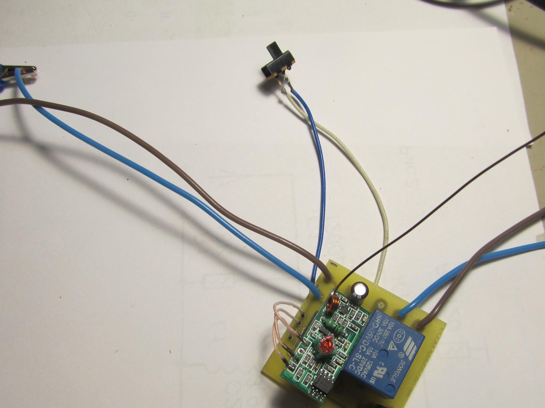
Now about the operation of the device itself. As you saw in the last photo, and on the receiver circuit itself, there is a K1 toggle switch. Its role is that when it is turned off, when you press the button on the transmitter, the relay on the receiver will turn on our lamp. And as soon as you release the button, the relay will also immediately turn off the lamp. Now if you turn on the toggle switch on the receiver, it goes into hold command mode.That is, if you press the button and release it, the relay will trip and the lamp will light all the time until you press the button again.
The diagram shows that there are three more free conclusions that you can connect different loads to.
Below: firmware files (TX transmitter, RX receiver), as well as video of the device
FIRMWARE
VIDEO WORKS
RF modules can be bought here: - from 35 to 45 rubles.