
What properties it will have: voltage, the battery will be 14 V, but the charging current will depend on the device. This charging method is provided by the car generator in standard operating mode.
The difference between this article and other similar ones is that the assembly of the product is quite simple. You do not need to make home-made boards, and fancy transistors.
Actually what we need:
1) a conventional power supply from a computer of approximately 230 watts, that is, the 12 V channel consumes 8 A.
2) 12V automotive relay (with four contacts) and two diodes per current 1A
3) several resistors of different capacities (depends on the model of the power supply itself)
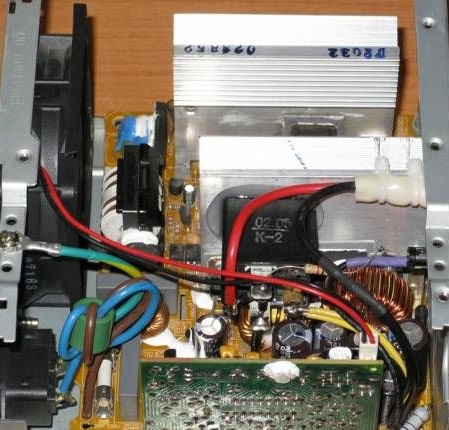
After opening this power supply, the author discovered that it was based on the UC3843 chip. This chip is used as a pulse generator and for protection against overcurrents. The voltage regulator on the output channels is represented by the TL431 chip:
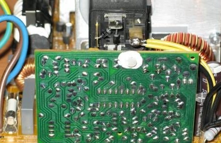
A tuning resistor was also installed there, which serves to regulate the output voltage in a certain range.
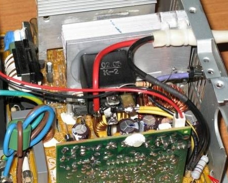
To make a charger from this power supply, we will need to remove unnecessary parts.
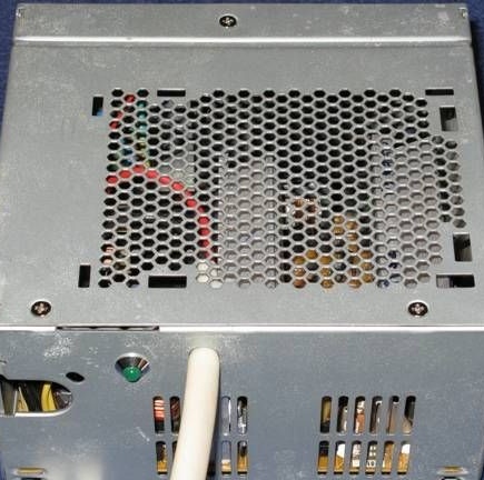
We disconnect the 220 \ 110V switch and all its wires from the board.
We do not need it, because our power supply will always work on voltage 220.
Then we remove all the wires at the output, except for the bundle of black wires (there are 4 wires) - this is 0V or "common", and the bundle of yellow wires (in the bundle of 2 wires) is "+".
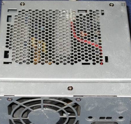
Then we will make the unit work continuously when connected to the network. As a standard, it works only if the necessary wires are closed in those bundles. It is also necessary to remove the overvoltage protection, since it turns off the unit if the voltage rises above a certain value.
The whole reason is that we need 14.4V at the output of the device and not the standard 12.
It turned out that the switching and protection signals operate through one optocoupler, and there are only three of them.
In order for the charging work to always have to close the contacts of this optocoupler with a jumper:
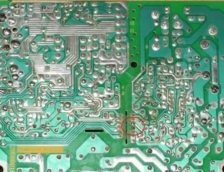
After this action, the power supply will work regardless of the voltage in the network.
The next step is to set the output voltage to 14.4V instead of 12. To do this, we had to replace the resistor, which was connected in series with the trimmer, with a 2.7kΩ resistor:
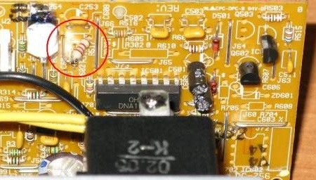
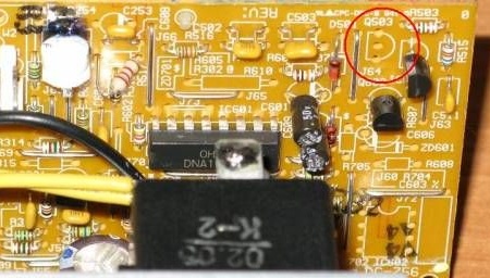
Now you have to dismantle the transistor, which is next to the TL431. (why is it unknown, but it blocks the operation of the microcircuit) This transistor was located at this place:
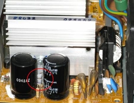
To stabilize, we add a load in the form of a 200 ohm 2W resistor (14.4v) to the output of the power supply, and a 68 ohm resistor for the 5V channel:
After installing these resistors, you can begin to regulate the output voltage without a load of 14.4V. To limit the output current to 8A (the acceptable value for our unit), you need to increase the power of the resistor in the power transformer circuit, which is used as an overload sensor.
Set the resistor to 47 Ohm 1 W instead of the standard.
And yet it does not hurt to add protection against connection with reverse polarity. We take a simple 12V car relay and two 1N4007 diodes. Also, to see the operation mode of the device, it would be nice to make another 1 diode and a 1kΩ 0.5W resistor.
The scheme will be as follows:
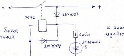
System of operation: when the battery is connected with the correct polarity, the relay is switched on due to the remaining charge in the battery. After the relay is activated, the battery is charging from the power supply through a closed relay contact, this will be shown to us by an external diode.
The diode, which is connected parallel to the relay coil, serves to protect against overvoltage when it is disconnected, arising due to the self-induction EMF.
To stick the relay - it is better to use silicone sealant, as it will remain elastic even after drying.
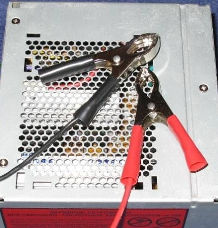
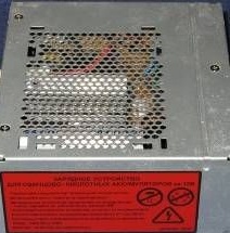
Then the wires are soldered to the battery. It is better to take flexible, with a section of 2.5mm2, about a meter long. To connect to the battery, crocodiles are used at the ends of the wires. To fix them in the case, the author used a pair of nylon ties (he pushed them into the holes drilled in the radiator)
At this work completed:

Comment: The device has disadvantages, for example, there is no indication of the degree of charge of the battery. But there are advantages: in 24 hours the battery is fully charged, and at the same time it may not turn off, as it will not “recharge” and will not deteriorate.