The author used an ionization chamber with an amplifier as a sensor, for the construction of which a composite transistor will be used. However, when the transistor was connected to the sensor, there was no electrical collector signal. It was assumed to obtain a leakage current due to the "instability" of the base and multiple gain. Perhaps it was precisely because of the model of the MPSW45A transistor that the leakage current was really small, but the gain remained high, the author suggests that about 30 thousand, and all this at a base current of about a couple of tens of picoamps.
For testing, we used a test resistor with a resistance of 100 MΩ, which was connected to an adjustable power source.
In this he saw the opportunity to adapt these standard components and make them a sensor with good sensitivity.
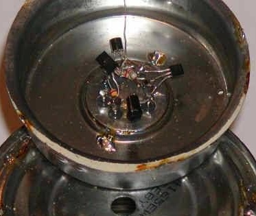
What is needed to collect the detector:
1) A pair of transistors
2) transformer
3) ammeter or voltmeter
4) some aluminum foil.
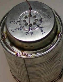
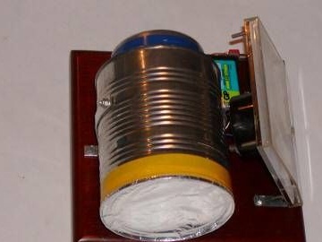
5) iron can with a radius of 5 cm
In a tin can we make a hole at the bottom, it is needed for antenna wires. The open part is covered with aluminum foil.
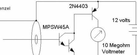
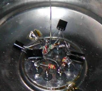
Connect a resistor to the base 2N4403 (10 kOhm) - this will help protect against damage during short circuit. The effectiveness of the system can be judged by the fact that it was able to detect a thorium glow network.
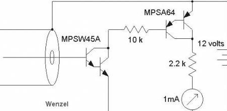
Then the author came up with the idea to connect another composite transistor. The result was approximately the following construction:
A voltage of 9 V was used for power, however, it is possible and even more preferable to apply a voltage higher, this is necessary to obtain sufficient potential in the ionization chamber.
Also, resistors were added, which should protect against short-circuit, because it can damage a transistor or ammeter.
Moreover, their influence on the function of the circuit in the standard mode of operation is very small, and therefore does not interfere with use.
Thanks to this, our circuit even after five to ten minutes, which are still necessary for stabilization. The ability to identify the heat grid was achieved at a distance of about ten centimeters.
However, this circuit turned out to be sensitive to temperature changes, therefore the ammeter readings changed with temperature changes, if it increased, the readings increased. Moreover, this happened even with small fluctuations.
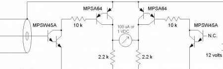
Because of this, it was decided to mount temperature compensation. To do this, the author made exactly the same circuit, this time again excluding the wires from the sensor connected to the transistor base. Instead, he stuck a measuring device between the output points of both circuits:
Although it looks rather confusing in the text, in reality it is carried out quite easily.
used another tin can to collect an analog circuit. It was also decided to fix all its parts on a circuit board with 8 leads, this was done for convenience and ease of operation.
You may have already noticed that in fact resistors with a resistance of 2.4 kΩ and 5.6 kΩ were used. I assure you that these differences in denominations are not particularly important in order to draw your attention to them.
A blocking capacitor was also used, which was connected in parallel with a battery with a capacity of about 10 μF. And the wire of our sensor itself was connected to the base of the transistor and, accordingly, passes through the hole e in the bottom of the can, which was previously drilled.
Note: the circuit has a good sensitivity to electric fields, therefore it is worth building a shell of the circuit such as this.
Before use, it is better to wait about five minutes after applying voltage to the circuit, after which the ammeter readings will change to very small values. If the ammeter readings are negative, just reconnect the wire from the sensor to the base of another transistor, and also change the polarity of the ammeter connection.
I would also like to warn that if a noticeable voltage drops on resistors with a resistance of 2.2 kOhm, it can be up to one volt, just clean everything with a solvent and put it to dry.
And after stabilizing the readings of the ammeter, you can safely proceed to the measurements. carrying a radioactive source in the form of, for example, a glow grid to the side with a closed foil, while the readings of the device should increase sharply.
You can use the voltmeter as a measuring instrument (scale to 1 V).
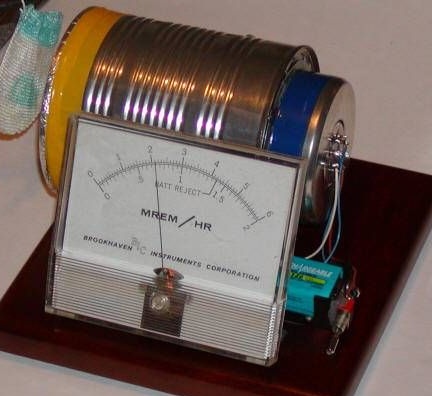
The device below is already equipped with a measuring scale, which was adjusted in units of radioactivity, and indications 2.2 arose due to the presence of a nearby glow grid.
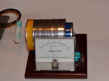
Well, we got a very simple sensor, especially considering its sensitivity. You can also improve the circuit by trying to connect transistors of a different power, a current amplifier.