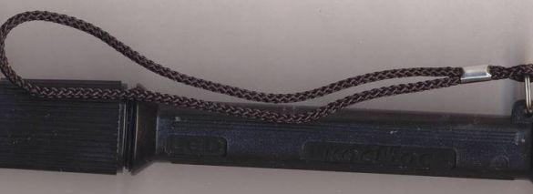
It all started with the fact that the Cosmos flashlight was bought, working on three finger-type batteries. He did not work long - refused after five starts. As it turned out, the LED burned out. To limit the current of the LED in the flashlight, a limiting resistor of 11 Ohms was provided. According to calculations, the resistance of this resistor should be above 40 ohms. Most likely, this was the reason for the failure of the LED. How to be Power it with a rated resistor? But it will be uneconomical, part of the energy (the third part) will be wasted. I had to make a simple step-up converter.
What gave such an upgrade:
1. Two batteries are used instead of three (the converter occupies the vacant volume of the third element).
2. Batteries are consumed as much as possible.
3. You can adjust the brightness of the LED by selecting the values of the capacitor and resistor R2.
4. If necessary, such a circuit can power up to four LEDs.
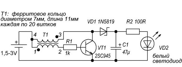
Here is the converter circuit:
The transformer is wound on a ring of ferrite, the diameter of which is 7 mm and the length is 11 mm. But the size of the ring is not critical and can vary. It is not worth splitting the ring for the convenience of winding, there are only 20 turns. The diameter of the wire for winding is chosen so as to completely fill the surface of the ferrite. The winding must be made immediately with two wires, previously twisted into a bundle. After this, it is necessary to connect the beginning of one winding with the end of the other. It is important here not to confuse anything, otherwise the converter will not start.
The transistor can be replaced with any high-frequency with a maximum collector current of at least 100 mA, structure n-p-n. The 1N5819 diode can be replaced with any Schottky diode with similar parameters, for example, 1N5817. You can use a regular, high-speed diode, but then the voltage drop on it will increase to 1 volt, which will slightly reduce the efficiency. Capacitor C1 is used for a voltage of 6.3 volts, but if the dimensions allow, you can put on a higher voltage. Resistor R2 can not be set, but it is important to control the current through the LED so that it does not exceed the maximum allowable for the LED.
With a properly assembled circuit, the converter starts working immediately, it is only important not to turn it on without load, since the voltage on the capacitor can rise to 50 volts and above, and the capacitor can fail. You should also once again check the polarity of the LED.
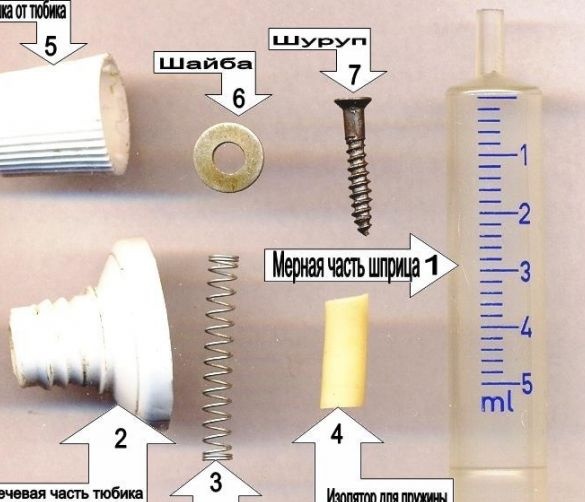
Now a little about the design of the converter housing.The necessary spare parts are shown in the figure.
1. 5 ml syringe (more precisely, its measured part, the converter frame will be made of it).
2. The humeral part of the aluminum tube with a cap (future minus).
3. A spring (for example, from an automatic ballpoint pen) and a small piece of cambric (PVC insulating tube of suitable diameter).
4. Self-tapping screw and washer (battery positive contact).
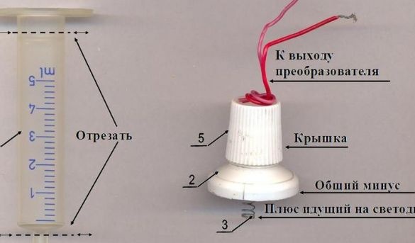
A tube for inserting needles and shoulders is cut off from the measured part of the syringe. The transducer is placed in the resulting case, its positive output is displayed in the hole for the needle, where then a screw with a washer is screwed. This will be the contact to the positive terminal of the battery. Now we take the shoulder part of the tube, insert the spring with the insulating tube on. This will be a positive contact going to the LED. It is necessary to solder the wire going to the anode (plus) of the LED. We fasten the negative wire of the converter to the shoulder of the tube, clamping it with a screw cap. Now the “plate” from the tube is inserted into the syringe and the converter is installed in the flashlight.


