This circuit was taken from Radiohobby Magazine No. 3 for 1999 and is a step-up voltage converter built on the principle of a blocking generator. Generation is carried out due to the positive feedback that controls the operation of the key transistor. In this case, short-time high-voltage pulses are generated on the secondary winding of the transformer. At the moment the converter is turned on, the fluorescent lamp has a high resistance, the voltage at its electrodes rises to 500 volts, but as soon as the lamp warms up, the voltage drops to 50 - 70 volts. Therefore, it is extremely important not to turn on the converter without load, since the voltage on it can grow up to 1000 volts, which can damage the transformer.
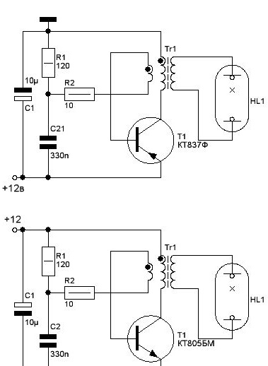
The figure shows two circuits, the upper one for the transistor of the p-n-p structure, the lower one for the transistor n-p-n. Naturally, when the transistor structure is changed, the polarity of the capacitor C1 also changes.
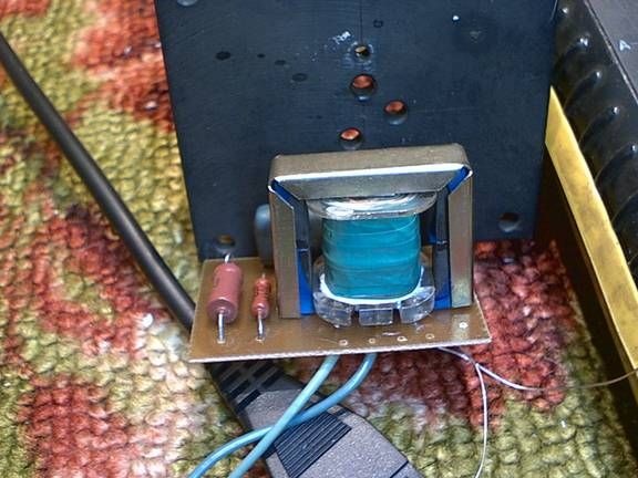
The transformer is manufactured on a 7x7 W-shaped ferrite with a magnetic permeability of NM2000. The secondary winding is wound first, according to the scheme it is connected to the LDS. It contains 240 turns wound with PEV-0.23 wire. After that, the winding is well insulated and a collector winding is wound on top of it - these are 22 turns wound with PEV-0.56 wire and the base winding, which contains 6 turns wound with PEV-0.23 wire. Naturally, the diameters of the wires can vary within small limits. The core required for the transformer to be manufactured can be obtained in an old disk telephone set, for example, TA-68. Then it is necessary to first remove all old windings from its frame. Also, a W-shaped core of a suitable cross-section of the magnetic circuit can be taken from a computer power supply. Important! Between the halves of the W-shaped core, a gap is necessary - a gasket of non-magnetic material. A sheet of thin paper, one layer of electrical tape, etc. will do. This is necessary so that the core is not magnetized, otherwise the converter will stop working after a short time.
For the correct operation of the circuit, it is necessary to configure the current consumed by the converter.To do this, you need to know the power of the applied LDS. Let's say its power is 20 watts. Then the current consumed by the converter should be 20W / 12V = 1.66A. This current is set by selecting the base resistor R1.
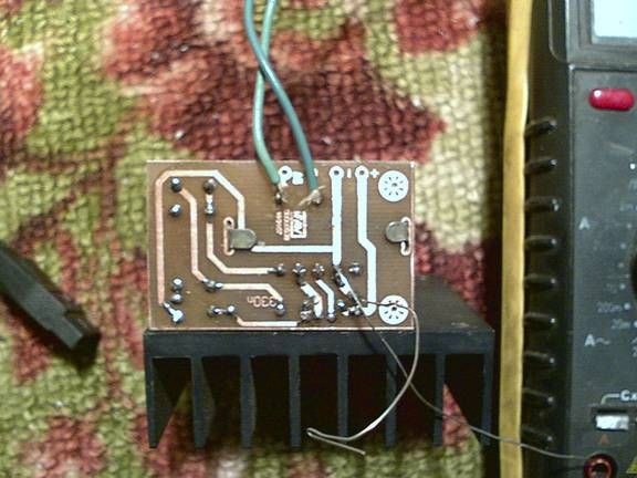
The transistor T1 must be placed on the radiator. The radiator area is chosen in such a way that after an hour of work it would be possible to calmly hold onto it. Instead of transistors KT837F and KT805BM, you can apply KT818 and KT819, respectively.
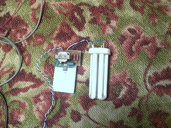
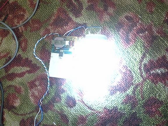
The operability of the converter is checked as follows. If immediately after turning on the converter the lamp lights up dimly, and after a split second flares up at full strength, then everything is working fine. If the lamp continues to work dimly, then it is necessary to select R1, or even change the transistor. The wires from the transformer to the lamp should be as thick and short as possible, otherwise the lamp will light up badly, or not light up at all.
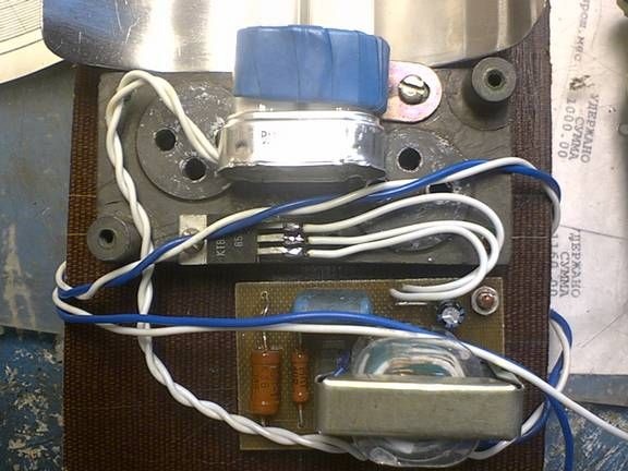
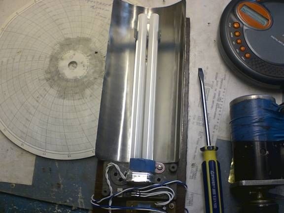
And now a few photos.