
For the manufacture of power supply units for power amplifiers, low-frequency 50 Hz transformers are usually used. They are reliable, do not create RF interference and are relatively simple to manufacture. But there are also disadvantages - dimensions and weight. Sometimes such shortcomings turn out to be decisive and one has to look for other solutions. Partially, the question of overall dimensions (more precisely, only heights) is solved by the use of a toroidal transformer. But such a transformer, due to the difficulty in manufacturing, costs a lot of money. And yet it still has significant weight. The solution to this problem may be to use a switching power supply.
But here its features: difficulty in manufacturing, or alteration. In order to adapt the computer power supply to the PA, it is necessary to re-solder half the board and, most likely, rewind the secondary winding of the transformer. But modern Chinese industry produces in large quantities 12-volt Tashibra power supplies and the like, promising a decent output power of 50, 100, 150 W and above. At the same time, the cost of such power supplies is ridiculous.
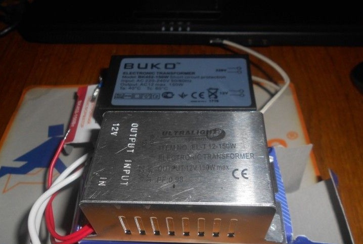
In the figure, a pair of such blocks, above BUKO, below Ultralight, but essentially the same Tashibra. They have small differences (they may have been made in different provinces of China): the secondary winding of Tashibra has 5 turns, and in BUKO - 8 turns. In addition, the Ultralight board is slightly larger, there are places for installing additional parts. Despite this, they are redone identically. During the finalization process, you must be extremely careful, since there is a high voltage on the board, after the diode bridge it is 300 volts. In addition, if you accidentally short-circuit the output, the transistors will burn.
Now about the scheme.
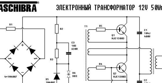
The scheme of power supplies from 50 to 150 watts is the same, the difference is only in the power of the used parts.
What needs to be improved?
1. It is necessary to solder the electrolytic capacitor after the diode bridge. Capacitor capacity should be as large as possible. With this alteration, a 100μF capacitor for a voltage of 400 volts was used.
2. It is necessary to replace the current feedback with voltage feedback. What is it for? In order for the power supply to start without load.
3. If necessary, rewind the transformer.
4. It will be necessary to rectify the output alternating voltage with a diode bridge. For these purposes, you can apply domestic diodes KD213, or imported, high-frequency. Better of course, Schottky. It is also necessary to smooth out the output ripple with a capacitor.
Here is a diagram of the converted power supply.
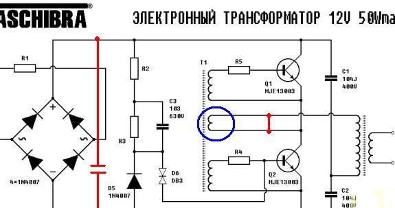
A blue circle indicates a current feedback coil. To disconnect it, it is necessary to drop out one end so as not to create a short-circuited winding. After that, you can safely close the contact pads of the coil on the board. After that, it is necessary to organize voltage feedback. For this, a piece of wire is taken from the twisted pair and 2 turns are wound on the power transformer. Then 3 turns are wound with the same wire onto the T1 communication transformer. After that, a 2.4-2.7 Ohm resistor with a power of 5-10 watts is soldered to the ends of this wire. A 12-volt light bulb is connected to the converter output, and a 220-volt, 150-watt light bulb is included in the gap in the power supply wire. The first bulb is used as a load, and the second as a limiter of current consumption. Turn on the converter in the network. If the network light does not light up, then everything is normal with the converter and you can remove this light. We turn it on again, without it. If the 12-volt light bulb on the load did not light up, it means that you did not guess with the direction of winding the communication coil on the T1 communication transformer and it will need to be wound in the opposite direction. Do not forget, after turning off the power, discharge the network capacitor with a 1 kΩ resistor.
The power supply for the ULF is usually bipolar, in this case it is necessary to obtain 2 voltages of 30 volts. The secondary winding of the power transformer has 5 turns. With an output voltage of 12 volts, 2.4 volts per turn is obtained. To get 30 volts, you need to wind 30 volts / 2.4 volts = 12.5 turns. Therefore, it is necessary to wind 2 coils of 12.5 turns. To do this, it is necessary to unsolder the transformer from the board, temporarily rewind two turns of voltage feedback and rewind the secondary winding. After that, the calculated two secondary windings are wound with a simple stranded wire. First, one coil is wound, then another. The two ends of the different windings are connected - this will be the zero output.
If it will be necessary to obtain a different voltage, more / less turns are wound.
The frequency of operation of the power supply with a voltage coupling coil is about 30 kHz.
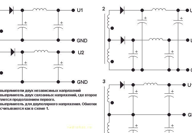
Then a diode bridge is assembled, electrolytes are soldered and ceramic capacitors are parallel to them to absorb high-frequency interference. Here are more options for connecting secondary windings.
It must be remembered that when the output is shorted, the power supply burns out - transistors, diodes and base resistors burn out.
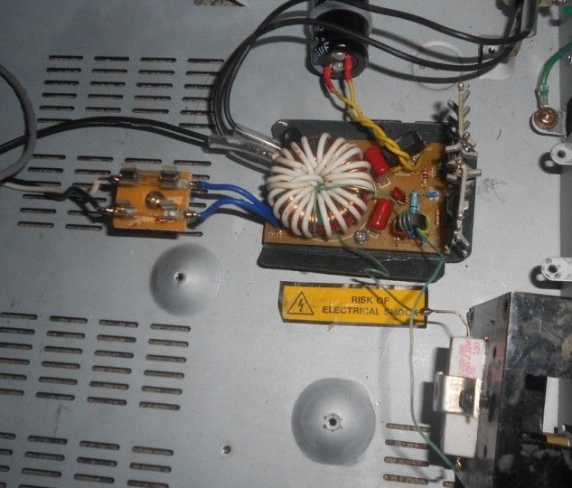
Well, a couple of photos of the converted power supply.
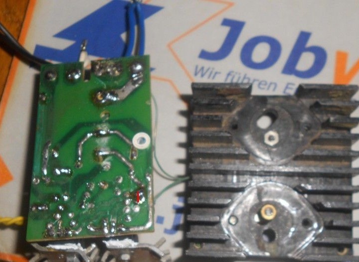
A red line on the board indicates the location of the shortening of the current feedback winding.