
Creating a microphone for a computer or camera is not at all difficult. But not every microphone can achieve the desired result in a certain situation. For example, because the microphone is elementarily insensitive.
In this case, you yourself need to assemble a small amplifier for a microphone that does not require power. Even for fans it will not be difficult to collect it.
Materials and tools:
- soldering iron
- tin and rosin
- transistor KT3102.
- A microphone from an old MKE-3 tape recorder (or any other similar in size).
- Resistor, capacitor and transistor from old el. schemes
- the wire
- plug 3.5 mm
- microphone housing
- electrical tape
Detailed manufacturing description:
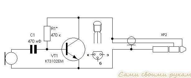
As the amplifier itself, the KT3102 transistor is used. The scheme is quite simple and shown in the figure.
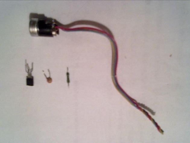
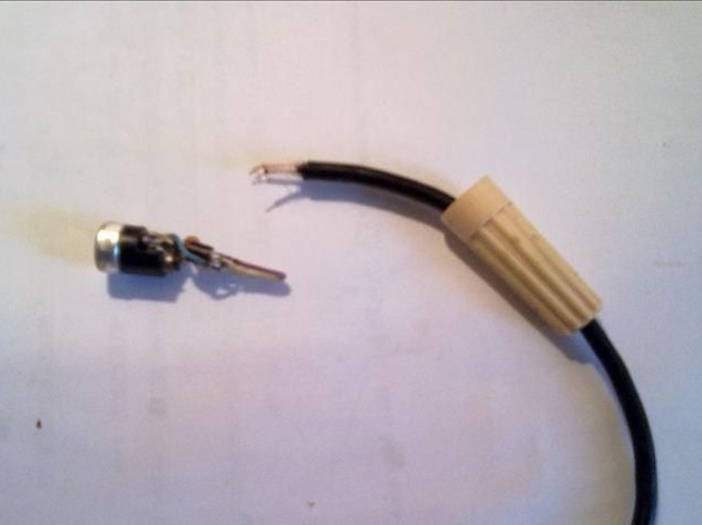
The microphone was taken by the MKE-3, which was pulled out of the old Spring tape recorder. 3 wires come out of it, we do not need one of them.
3 wires come out of the microphone - yellow, blue and red. It is red that is not needed and will not be used. After it is cut, it will be possible to shorten the other two wires as shown in the photo.
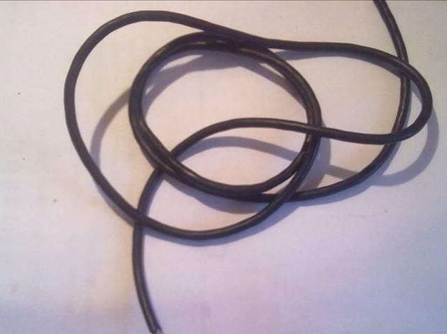
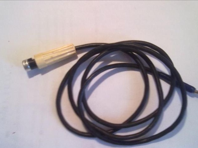
The wire for this microphone was taken from the adapter to the tape recorder. In this type of wire there are three wiring. Here, as above, the third is superfluous, so only two of them are used. On each side, each transaction is cleaned.
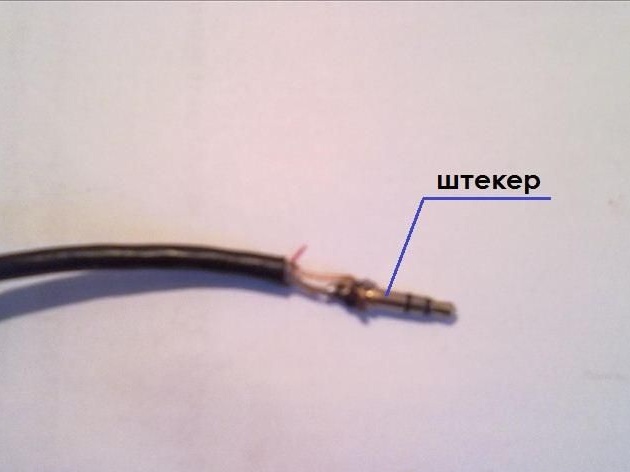
A plug is soldered to the prepared wire as shown in the amplifier circuit, but first you need to process each wire with rosin and tin.
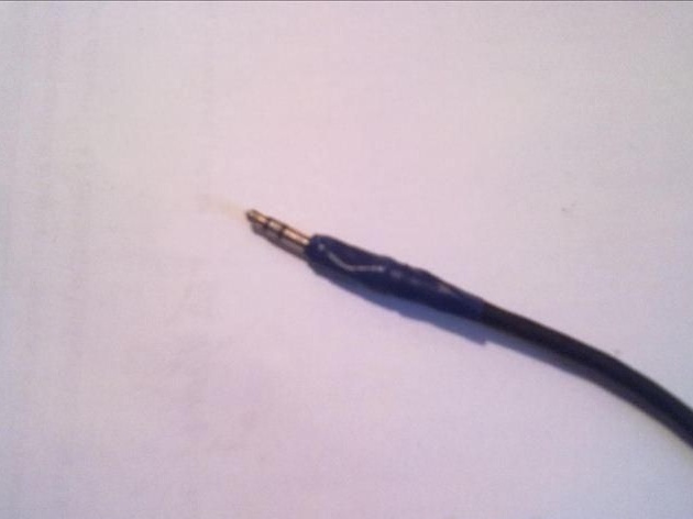
After soldering, insulate the wire with electrical tape.
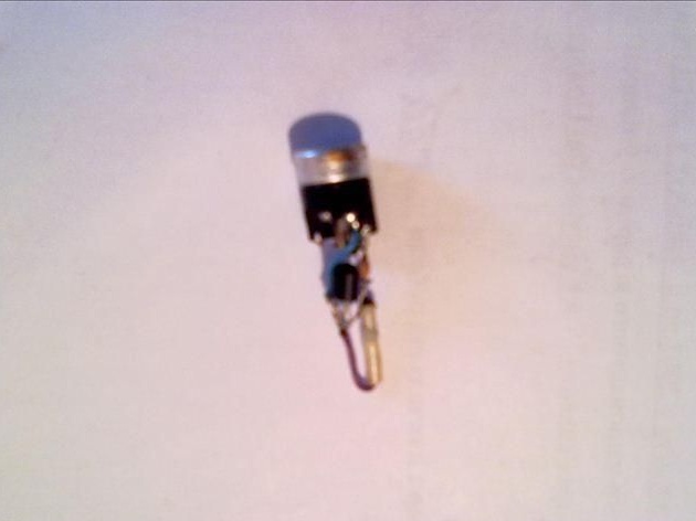
Next, the amplifier itself is assembled as shown in the diagram. Several stripped wires are prepared on both sides. Next, each part is soldered as shown in the amplifier circuit. It is soldered so that the amplifier turns out to be minimal in size, in order not to use a large case. The location of the transistor contacts is shown in the diagram. When soldering, it is better not to heat its contacts for a long time. The photo shows an amplifier already soldered with a microphone.
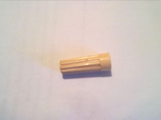
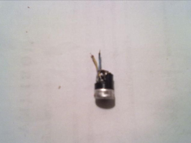
The housing here is the housing removed from the old pickup plug. You can use it more beautifully if you have one.
Next, the wire slips into the housing as shown in the photo.
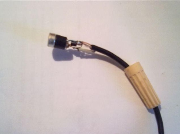
The stripped wires are soldered as in the scheme, and in the end it turns out as in the photo.
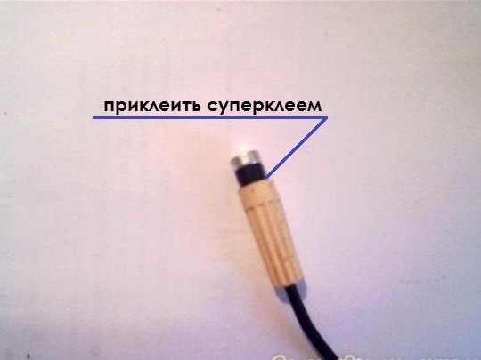
After everything is soldered and connected, an amplifier with a microphone is finally placed in the case. The author did not fit the entire microphone into the case, so I had to glue it with super glue as shown in the photo.
After all this, you can fully use this microphone.