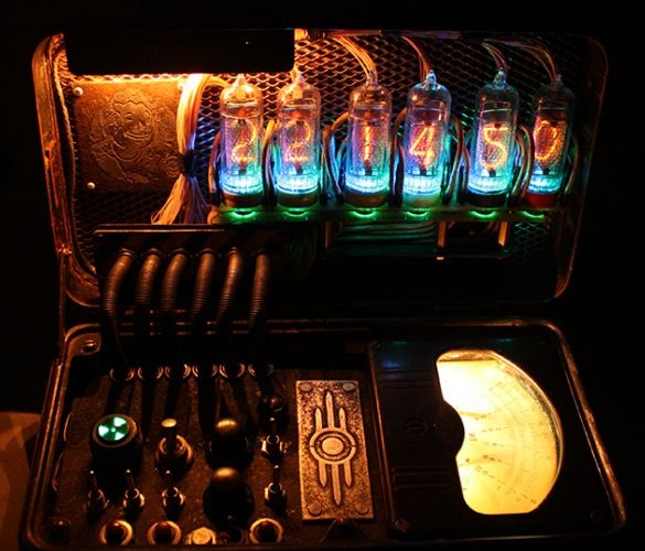
In this article I will talk about one very interesting homemade. Tube clock in the style of the well-known game "Fallout". Sometimes you wonder what some people are capable of. Fantasy, with straight arms and a clean head, works wonders! Well, it's time to start a story about a real work of art :)
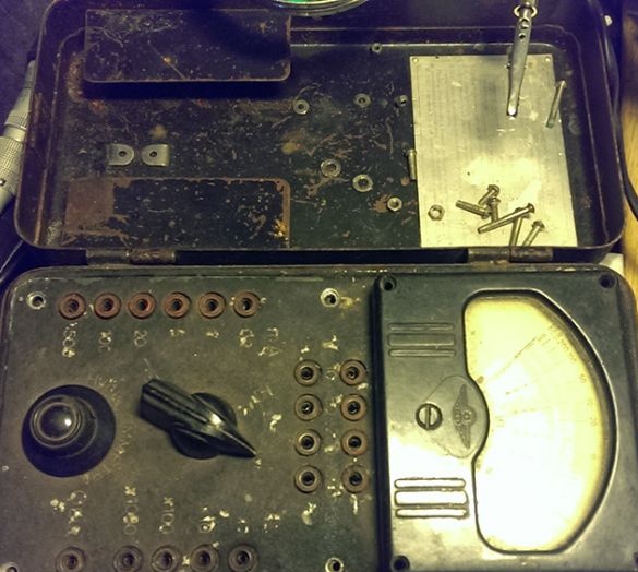
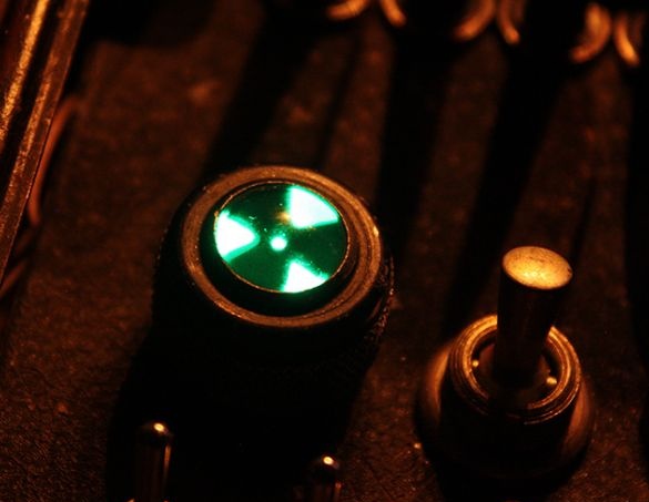
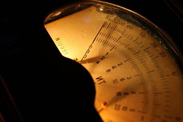
In his product, the author uses only output components, tracks on a printed circuit board with a width of at least 1 millimeter, which, in turn, is very convenient for beginners and inexperienced amateur radio enthusiasts. The entire circuit on a single board, the component rating and the components themselves are indicated. Since the author of the product could not determine the color of the LED backlighting of the lamps, it was decided to use the PIC12F765 controller to adjust the RGB LEDs. Incandescent lamps, which give a cozy light, are also used to illuminate the dashboard and ammeter. Some parts and the case itself were taken from the old (1953 release) Soviet TT-1 multimeter. I would like to use only original parts from this multimeter, so it was decided to keep the ammeter with a dashboard, and plug the discharge indicators into a place under the cover. But the first problem arose - there is too little space for indicators under the lid, so the lid simply could not close together with the indicators inside. But the author found a way out - to slightly drown the panel into the case and make the ammeter a little smaller in volume.
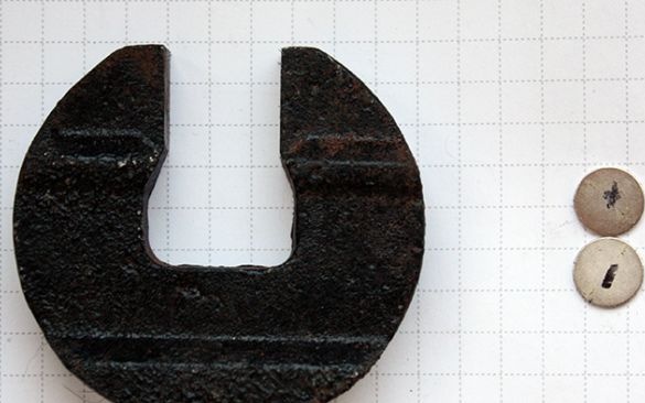
The hefty ferrite magnet was replaced by two miniature neodymium ones, in general, the author removed all unnecessary details to make room for the filling, while preserving the functionality of the TT-1. The ammeter is planned to be connected to the foot of the MK, which regulates the current supply to the anode at the sixth lamp, which is responsible for the image of seconds, so the hand will move in time with the changing seconds on the lamp.
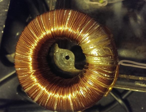
The author used a 0.8A toroidal transformer to convert a voltage of 220 volts to 12 volts. It is a pity that the transformer could not be placed outside the case, because it is so consistent with the design of Fallout.
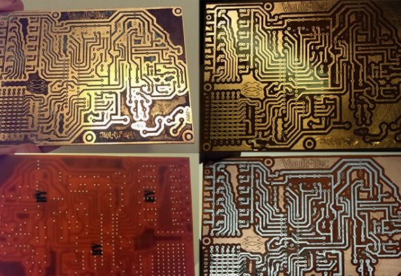
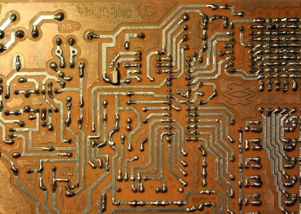
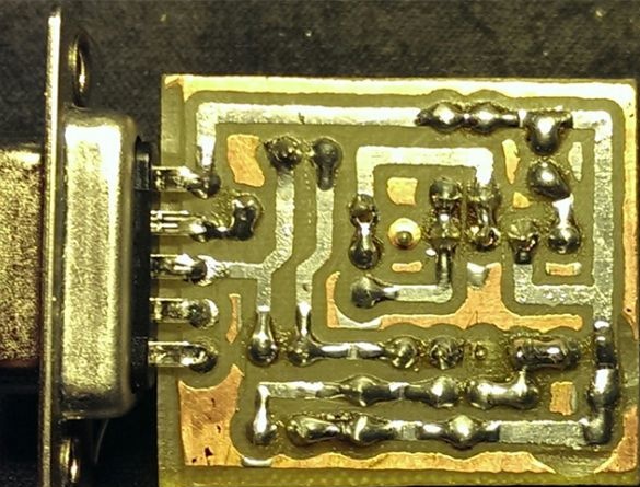
The board is made according to LUT technology standards. Designed for housing dimensions.
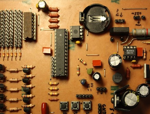
The author pays special attention to the DS1307 watch microcircuit. In the photo, it is in a DIP-case, but the wiring for this chip is made for SMD, so the legs are turned in the opposite direction, and the chip itself is stuck with its belly up. Instead K155ID1 was used KM155ID1, the author claims that only with the replaced part was it possible to avoid glare. Placement of elements on the board:
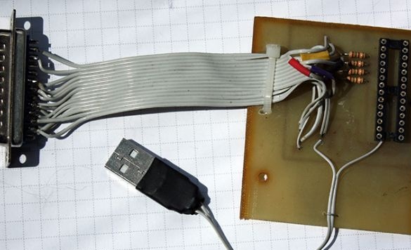
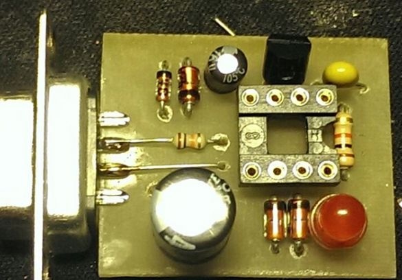
The author has assembled the simplest LPT programmer for programming K ATMega8 (firmware for ATMega8, all boards, firmware for PIC at the end of the article)
PIC programmer:
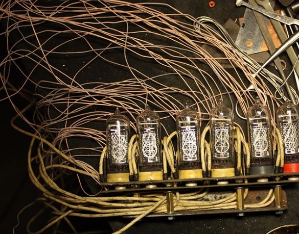
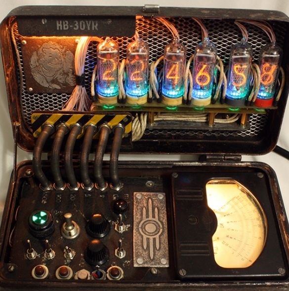
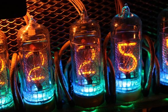
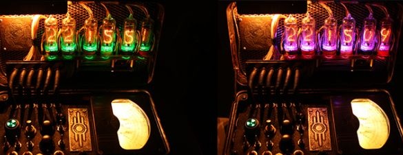
IN-14 gas-discharge indicators have long soft leads for soldering, but because of their limited life, it was decided to make them easily replaceable. Therefore, the author used collets from the panel of DIP microcircuits, and the IN-14 legs were shortened to the depth of the collets. The holes in the center of the slots are made specifically for the LEDs, which are located under the lamps on a separate board. LEDs are connected in parallel, one resistor serves to limit the current to color.
This is how discharge indicators mounted in an aluminum corner look.
The mount, in the role of which is an aluminum corner, is etched in ferric chloride, because of this he is very old visually, which gives more surroundings. As it turned out, aluminum reacts very violently with ferric chloride: a very large amount of chlorine and heat is released. Of course, the solution after such tests is no longer suitable for use.
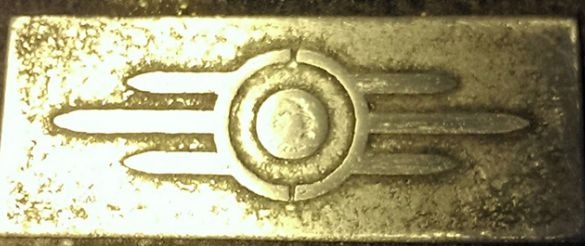
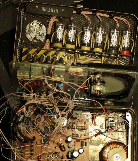
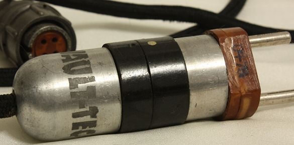
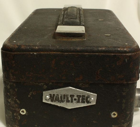
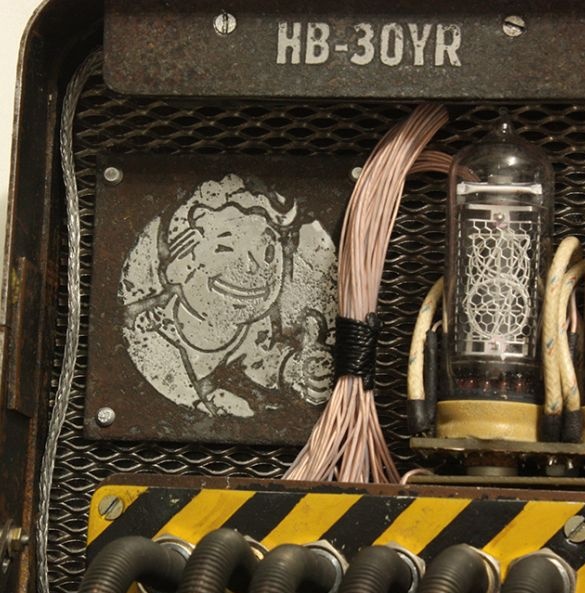
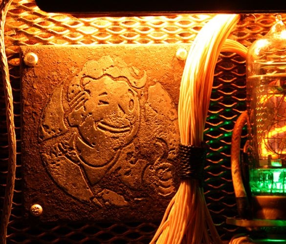
Other details were performed using a similar technology (LUT) (fallout-boy logo, Vault-Tec, and HB-30YR number). The device was intended for a gift to a friend on his 30th birthday. Who does not understand, the number HB-30YR stands for Happy Birthday - 30 YeaRs :)
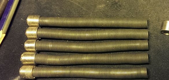
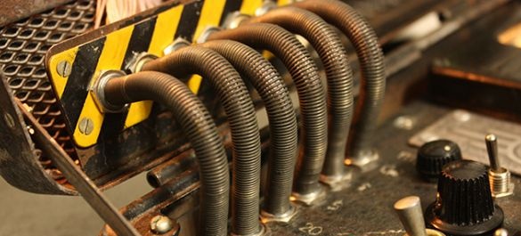
The author used a nichrome spiral with F-type antenna connectors at the ends for wiring between the body and the cover. Fortunately, there were 6 holes on the panel in the right place, and they served as connectors for the wires.
Watch before complete assembly. The wires, of course, are not laid out neatly, but this will not affect the functionality in any way.
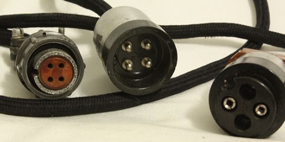
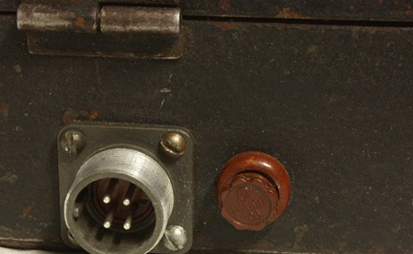
Power cord. Some old military connectors. The author made the adapter to the plug himself.
A power cable connector and a fuse on the bottom of the chassis.
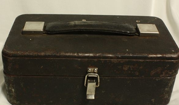
View of the device in a closed state. Indeed, it is not much different from the TT-1.
General view of the device.
Stop to prevent the lid from tipping over.
Watches in the dark look most profitable.
P.S.
ATTENTION! In the Sprint Layout program, the capacitor polarity is mixed up and the zener diodes are designated as diodes, and their ratings are not indicated.
I wish everyone who read this article inspiration and desire for knowledge!
Files:
All details:
View online file:
All boards:
RGB_LED (firmware for PIC):
Firmware for ATMega8 (by BARS):

